Published by Zorapid Precision Manufacturing
If you’re a mold designer, product engineer, or production manager, you’ve lived this nightmare:
You lock in your injection parameters, tweak melt temps, slow down fill speed, and still end up with ugly black burn marks trapped at rib tips, weld lines, or blind bosses. Or worse—consistent air traps causing short shots, weak weld seams, and rejected cosmetic parts.
You spend hours tuning machine settings, but the defects never fully go away. Why?
9 out of 10 times, it’s not your process—it’s your mold venting system. Poor vent layout, wrong vent depth, or missing hidden vent paths create permanent gas entrapment that no machine tweak can fix long-term.
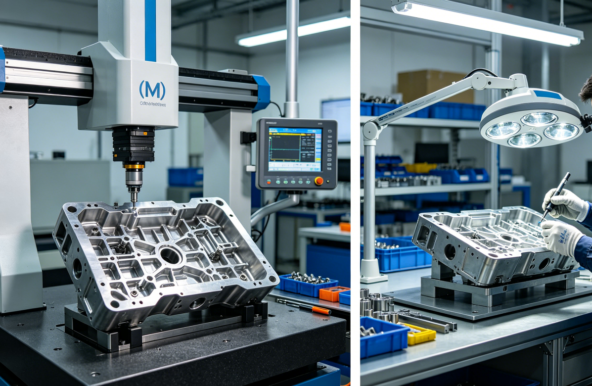
At Zorapid, our mold engineering team runs Moldflow simulation on every NPI project, and we’ve eliminated 100% of chronic burn mark & air trap failures for medical, automotive, and electronics customers by following standardized venting design rules. Today, we’re breaking down actionable, field-tested venting principles you can implement on your next mold—no costly rework required.
First: Understand Why Air Traps & Burn Marks Happen (The Diesel Effect Simplified)
Let’s skip textbook jargon and keep this practical for production teams.
When molten plastic fills your cavity, it pushes all air, moisture vapor, and plastic decomposition gases ahead of the melt front. If those gases have no escape route, they get compressed instantly—this is the diesel effect. Compressed air spikes above 900°F in milliseconds, scorching plastic resin and leaving permanent brown/black burn marks on your part surface.
Common air trap hotspots you’ll always see:
- Last-to-fill cavity extremities
- Deep ribs, tall bosses, blind holes
- Weld line intersections where two melt fronts collide
- Runner cold slug dead ends
- Thin-wall narrow geometry far from the parting line
Many teams make the mistake of lowering injection speed to “avoid burns.” This only slows production cycle time and doesn’t eliminate trapped gas at the root. Proper venting lets you run full fill speed without defects, cutting cycle times while boosting yield rates.
Quick Defect Checklist to Confirm Venting Is Your Issue
Your problem is vent-related if all these match:
- Burn marks / air bubbles appear in identical spots on every shot
- Lower melt temperature does not erase the defect
- Increasing injection pressure makes burns worse, not better
- Short shots only improve slightly after maxing out hold pressure
6 Non-Negotiable Core Mold Venting Design Principles (Zorapid Standard DFM Rules)
These are the design rules we embed into every mold drawing before steel cutting—our primary method to eliminate air traps and burn marks permanently.
Principle #1: Vent Every Predicted Last-Fill Zone (Moldflow Simulation Is Mandatory)
Never guess where air gets stuck. Run Moldflow or Moldex3D flow simulation first to map fill progression, weld lines, and air trap coordinates. We add vents directly at every simulation flagged gas pocket before machining the mold cavity.
Field trick from Zorapid engineers: Run short-shot tests during mold sampling. Stop fill at 60%, 75%, 90% volume and photograph the melt front. Any area plastic fails to reach fully is a guaranteed air trap that needs venting.
Principle #2: Match Vent Depth Exact to Your Resin (Flash vs. Vent Flow Balance)
The single biggest venting mistake is using one-size-fits-all vent depth. Vents must be shallow enough to block plastic flash, yet deep enough to evacuate compressed air instantly.
Below is our Western-standard material vent depth chart (imperial + metric for US/EU clients):
| Material Family | Recommended Vent Land Depth | Use Case Notes |
|---|---|---|
| PP / PE / PS (low viscosity) | 0.0005–0.0012 in (0.013–0.03 mm) | Consumer housings, thin-wall parts |
| ABS / PC / PC+ABS | 0.001–0.0015 in (0.025–0.038 mm) | Electronics, cosmetic enclosures |
| Nylon / PA66 GF | 0.0003–0.0005 in (0.008–0.013 mm) | Glass-filled grades clog vents faster |
| PMMA / Optical Acrylic | 0.0015–0.002 in (0.038–0.05 mm) | Stepped vent design to avoid surface witness lines |
| Flame-retardant plastics | Reduce depth by 30% | FR additives leave heavy vent residue |
Key rule: Vent land length stays 0.125–0.25 in (3–6 mm) to seal melt before plastic bleeds into vent channels. Widen vent relief channels behind the land to speed gas exhaust—we machine relief depth to 0.04–0.08 in for all production molds.
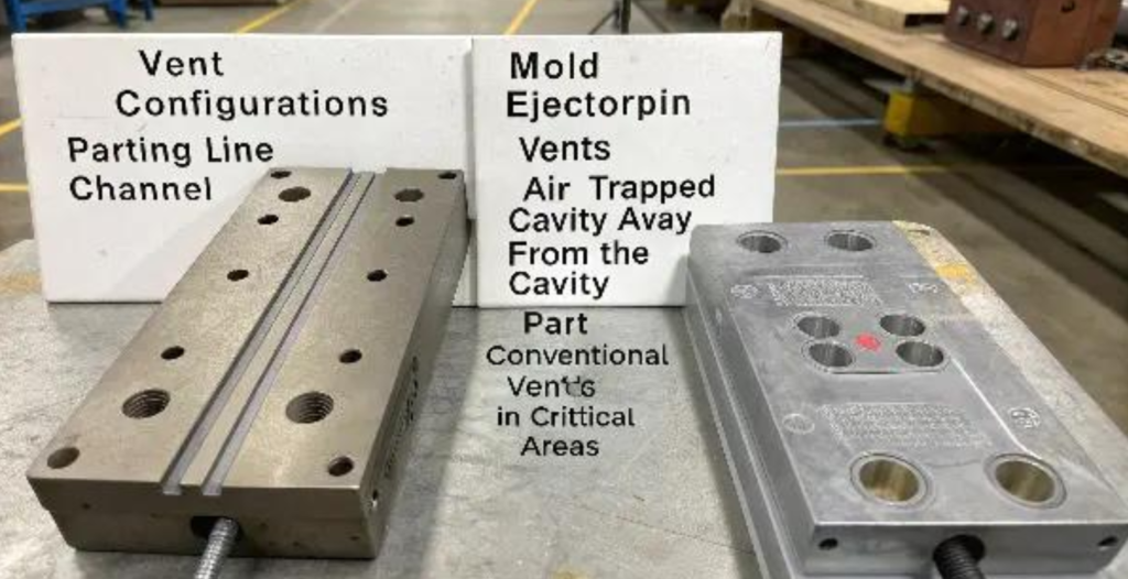
Principle #3: Deploy Multiple Vent Types for Complex Geometry (Don’t Only Rely on Parting Line Vents)
Parting line perimeter vents work great for simple flat parts, but deep ribs, isolated bosses, and blind pockets need secondary venting solutions. At Zorapid, we combine three vent styles for complex medical & automotive molds:
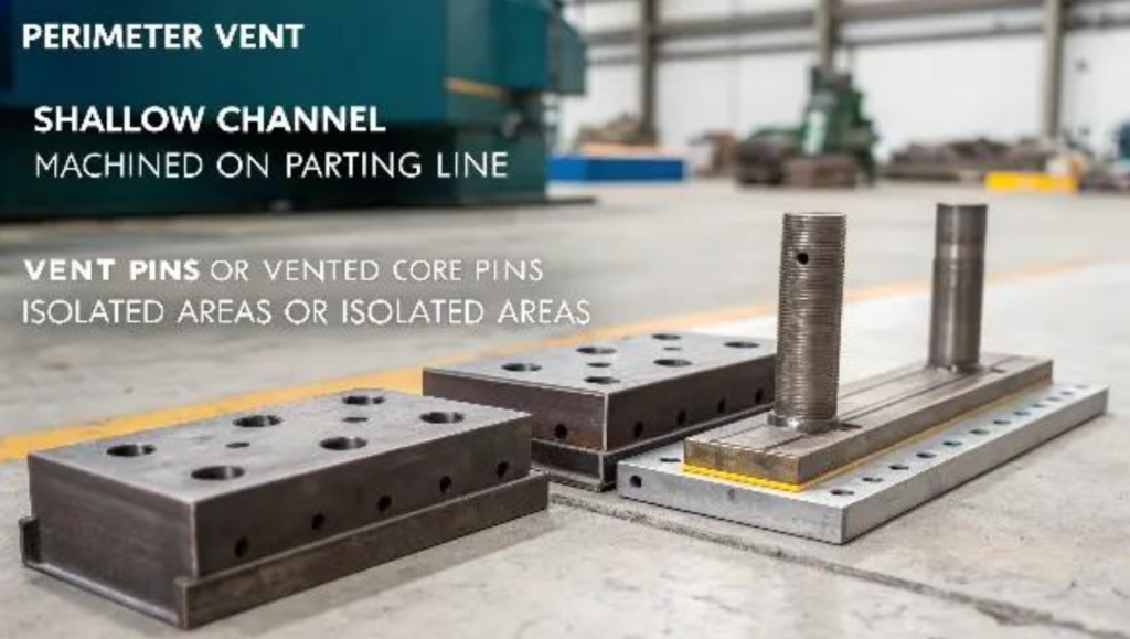
- Parting Line Perimeter Vents (Base Standard) Machine continuous shallow vent slots around the full cavity edge. Spacing every 50–75 mm for large mold bases. Ideal for outer perimeter air release, easy to clean during maintenance.
- Vented Ejector Pins / Core Pin Vents For deep bosses and blind holes far from the parting line: grind a tiny annular gap between ejector pin and core steel. This creates a hidden vent path at the absolute bottom of rib/boss features where air always accumulates.
- Split Insert Vents + Porous Metal Vent Inserts Ultra-complex deep cavities, optical lenses, and high-flow thin-wall parts get porous metal inserts. The sintered steel micro-pores release uniform gas without leaving visible vent marks on A-surface cosmetic parts. Perfect for medical-grade low-defect requirements.
Principle #4: Route All Vent Relief Paths Straight to Atmosphere
Trapped gas cannot escape if vent channels dead-end inside the mold base. Every vent relief channel must machine all the way to the mold exterior. Avoid winding, narrow, or blocked vent runs—they create backpressure that recreates air traps mid-fill.
Safety add-on: Angle external vent exits away from machine operators to prevent hot gas flashbacks during high-speed injection.
Principle #5: Design Vents for Easy, Fast Maintenance
Vents clog with plastic residue, FR ash, and mold release agent buildup after thousands of shots. Clogged vents instantly bring back burn marks and air bubbles.
Zorapid maintenance-focused design rules:
- Make vent lands wide (3–10 mm) for simple sanding/cleaning
- Use removable vent inserts for high-volume production molds
- Avoid tiny, narrow vent slots that trap debris permanently Schedule vent cleaning every 3,000–10,000 shots—more frequent for flame-retardant, filled, or hygroscopic materials like nylon and PBT.
Principle #6: Vent Runner & Cold Slug Wells Too (Overlooked Gas Source)
Gases form inside the runner system before plastic enters the cavity. Always add small vents at runner branch ends and cold slug pocket terminals. Hot runner molds require auxiliary venting at nozzle tips to eliminate pre-cavity gas buildup that causes random surface burns.
Zorapid Step-by-Step Fix Workflow to Fully Eliminate Burn Marks & Air Traps
We follow this systematic process for every customer mold sampling, and it resolves vent-related defects in 1–2 sampling rounds without full mold rework:
- Run Moldflow simulation pre-machining to map all air trap coordinates
- Machine primary parting line vents matching resin depth specs
- Add ejector pin / split insert vents for deep rib/boss air traps
- Complete short-shot fill testing to validate unvented hidden zones
- Adjust vent land width/depth incrementally if minor burns persist
- Polish vent channel interiors to reduce residue buildup
- Document vent layout & maintenance schedule for mass production handoff
Real-World Zorapid Case Study (Automotive EV Connector Mold)
A European EV client brought us a GF-PA66 connector mold with consistent burn marks at 8 internal boss tips, causing 40% part rejection.
Original mold only used perimeter parting line vents, no pin venting on deep bosses. Our team’s fix:
- Added vented ejector pins at every boss base
- Reduced vent land depth slightly for glass-filled PA66
- Expanded relief channels to speed gas evacuation Result: Zero burn marks, zero air traps, rejection rate dropped to <0.5%, production cycle time shortened 12% from faster injection fill speeds.
Common Venting Design Mistakes Western Mold Shops Keep Repeating
Avoid these costly errors that lead to repeated sampling delays and scrap parts:
- Cutting vents too shallow to save flash risk → air can’t escape, permanent burn marks
- Only venting the main parting line, ignoring deep rib/boss hidden air traps
- Using identical vent depth for all materials (glass-filled vs. unfilled resins require different specs)
- Dead-end vent relief channels that trap gas inside the mold base
- Narrow, hard-to-clean vent slots that clog after minimal production runs
- Skipping Moldflow simulation and guessing air trap locations
- Forgetting runner & cold slug venting, creating upstream gas contamination
How Zorapid Builds Venting Into Our End-to-End DFM Service
Unlike mold makers that only cut vents post-sampling as a band-aid, we integrate venting design at the earliest NPI stage:
- DFM design review flags air trap risks during part CAD optimization
- Moldflow flow simulation generates official vent placement drawings
- Precision CNC grinding & laser machining for consistent vent land depth (±0.002 mm tolerance)
- Replaceable vent inserts for high-volume medical/automotive mass production
- Full vent maintenance documentation included with mold delivery
- On-site sampling team adjusts vent geometry during first trial to lock zero-defect parameters
Our 3,000 m² precision manufacturing center specializes in injection molds for medical, aerospace, EV, and consumer electronics, with ISO & AS certified quality control for Western OEM compliance.
FAQ
Can I fix burn marks just by adjusting injection machine settings instead of reworking mold vents?
Temporary relief only. Lower fill speed reduces burn severity but slows cycle time and cannot fully eliminate trapped air. Any permanent fix requires optimized mold vent geometry. 70% of burn mark cases resolve completely with vent redesign alone, no parameter changes needed.
How deep should vents be for medical-grade PC/ABS optical parts?
Stick to 0.001–0.0015 in vent land depth with stepped vent relief. We use laser-machined ultra-smooth vents to avoid visible vent witness lines on A-surface medical housings.
Do porous metal vent inserts add significant mold cost?
Minor upfront cost offset by near-zero defect rates and reduced sampling iterations. For high-volume cosmetic or medical molds, porous metal vents deliver long-term production savings.
How often do I need to clean mold vents during mass production?
Clean every 2,000–5,000 shots for FR, glass-filled, or hygroscopic resins. Clean every 10,000–20,000 shots for clean PP/PE unfilled materials. Burn marks reappearing consistently are the clearest sign vents are clogged.
Final Wrap-Up
Mold venting isn’t an afterthought—it’s the foundation of defect-free injection molding. When you follow material-specific vent dimensions, deploy multi-style vent layouts for complex geometry, and validate air trap locations with Moldflow simulation, burn marks and air traps become fully solvable issues, not permanent production headaches.
At Zorapid, we build venting excellence into every mold from the first CAD review, eliminating costly rework and sampling delays for our global OEM partners. If you’re struggling with persistent air trap or burn mark defects on your current mold, reach out to our DFM engineering team for a free vent design audit today.