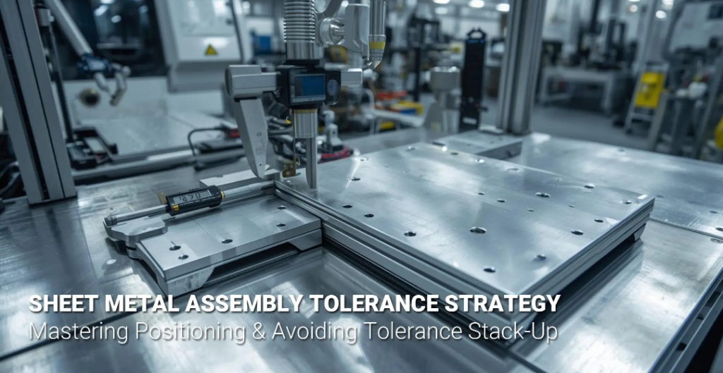
Published by Zorapid
Precision Sheet Metal Fabrication & Assembly Blog Meta Description: Tired of sheet metal parts passing single-part QC but failing final assembly fit? Zorapid breaks down stack-up control, GD&T, DFM tweaks, fixturing and factory QC workflows to lock consistent tolerances for multi-panel combined sheet metal assemblies, with real OEM case data.
Sourcing multi-panel sheet metal assemblies — machine frames, equipment enclosures, electrical cabinets, EV power housings? You’ve run into this frustrating headache:
All separate parts pass single-piece QC, yet stacking, riveting, welding or bolting brings warped gaps, misaligned mounting holes and ill-fitting key interfaces.
This is tolerance stack-up—the top cause of rework, scrap and shipping delays for sheet metal assemblies globally.
Unlike solid CNC parts, sheet metal has inherent variance: laser kerf, bend springback, weld heat warp and coating shrinkage. Tiny flaws compound across 3, 5, 10+ mating panels, pushing total deviation past your functional limits.
At Zorapid’s 3,000㎡ integrated sheet metal workshop, we build thousands of multi-part sheet metal assemblies monthly for EU, US, and Australian OEMs. Over two decades of mass production, we’ve built an end-to-end tolerance control system that eliminates unmanageable stack-up before production even starts, delivering consistent fit, uniform gaps, and zero forced assembly rework from prototype to high-volume batches.
No boring textbook formulas here. This blog shares shop-tested, usable tolerance control strategies tailor-made for sheet metal assemblies, backed by real production data and customer cases you can use straight on your next build.
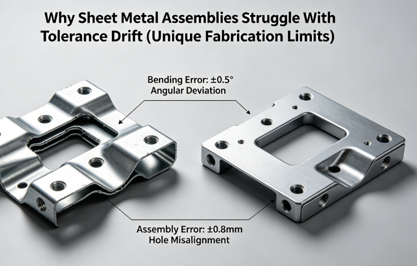
Why Sheet Metal Assemblies Struggle With Tolerance Drift (Unique Fabrication Limits)
First, let’s cover the inherent sheet metal process variations that turn single-part compliance into assembly failure:
- Bend springback: Every folded flange rebounds slightly after bending; ±1° angle drift shifts hole positions across long multi-bend panels
- Laser cutting kerf variation: Minor beam drift creates ±0.08~0.15mm linear offset across cut edges and hole patterns
- Weld thermal distortion: Localized heat warps flat panels, twisting datums and mating surfaces after assembly welding
- Coating thickness shift: Powder coating/anodizing adds uneven material thickness, tightening gaps and blocking fastener insertion
- Raw sheet thickness inconsistency: Minor gauge variance changes flange height and mating contact flatness across batches
Small prototype runs with manual hand-fitting hide these flaws. Once you scale to mass assembly lines, these compounded variations create non-conforming units at scale.
DFM Tolerance Stack-Up Analysis Before Laser Cutting
Fixing tolerance stack-up after manufacturing is costly and slow. Our top control measure kicks off with complimentary pre-production DFM reviews — before any metal gets cut.
Zorapid’s DFM Stack-Up Workflow For Multi-Part Assemblies
- Extract all critical functional interfaces (PCB mounting holes, hinge datums, sealing flanges, connector cutouts)
- Map full tolerance chains across every mating panel using RSS (Root Sum Square) statistical analysis to calculate worst-case total assembly drift
- Flag over-constrained dimension chains that will exceed acceptable gap/position limits during assembly
- Issue two tiers of design fixes: minor CAD tweaks (adjust hole sizes, add slots) or datum restructuring to break long stack-up loops
- Provide revised tolerance callouts matched to our sheet metal process capability (standard laser ±0.1mm, bend ±1°)
Real-world example: A 4-panel cabinet design originally had a 1.2mm worst-case stack-up gap variance; our DFM datum restructuring cut total accumulated drift down to 0.35mm without loosening critical functional tolerances.
Critical rule we enforce for all OEM clients: Never reuse CAD default generic tolerances for multi-part assemblies—default linear tolerances almost always create unmanageable stack-up across combined sheet metal frames.
Datum & GD&T Setup To Break Long Tolerance Chains
The biggest mistake engineers make on sheet metal drawings is dimensioning every feature from random part edges, creating endless tolerance chains. Proper datum reference frames + GD&T eliminate this risk entirely.
Datum Best Practices For Combined Sheet Metal Assemblies
- Assign one shared primary datum surface across all mating panels (the main flat mounting base that locks assembly position)
- Use the 3-2-1 locating principle for every component: 3 points to lock flatness, 2 to lock horizontal shift, 1 to lock rotation—removes all six degrees of freedom variation
- Reference all critical holes, cutouts and flanges back to the unified datum frame, not local bend edges or cut borders
GD&T For Sheet Metal Assembly Tolerance Control
Swap generic ±X linear tolerances for True Position GD&T on all mounting holes, plus MMC modifiers to add built-in assembly bonus tolerance.
- Floating fastener formula we use for all panel bolt holes: Position Tolerance = Min Hole Diameter – Max Fastener Diameter, guarantees bolt insertion even with minor part drift
- Use profile tolerances to lock sealing flange flatness with one callout—way more reliable than piles of separate linear dimensions.
- Separate cosmetic gap tolerances from functional positional tolerances—only apply tight GD&T where fit and performance depend on it, avoid over-tolerancing non-critical surfaces that inflate production cost
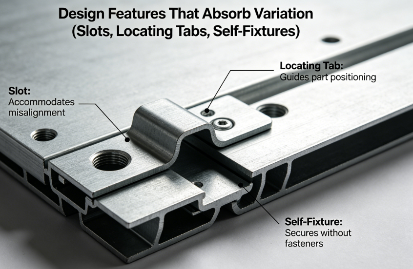
Design Features That Absorb Variation (Slots, Locating Tabs, Self-Fixtures)
Even with perfect DFM and GD&T, minor manufacturing variation is unavoidable. We build intentional variation-absorbing geometry into every assembly design during our review to eliminate fit failure.
Top Variation Buffer Features For Combined Sheet Metal Assemblies
- Elongated adjustment slots for secondary mounting holes Replace tight round holes with horizontal/vertical slots for non-critical fastener points; absorbs up to ±0.8mm of stack-up drift without functional impact
- Integrated self-locating tabs & slots Interlocking formed tabs on mating panels lock relative position during assembly, replacing loose manual alignment and cutting fixture dependency
- Controlled clearance gaps for mating panels Calculate minimum functional gap from stack-up analysis; add 0.2~0.4mm intentional clearance for powder coating and bend variation
- Separate machined datum bosses for ultra-precise assemblies CNC machine small aluminum datum pins on critical sheet metal frames—machined features hold ±0.05mm vs standard sheet metal ±0.15mm hole positioning, isolating tight tolerance zones from formed panel variation
- Floating hinge/connector brackets Mount secondary components on small independent sub-panels with slotted holes to absorb frame-level stack-up without misalignment of sensitive electrical parts
These design tweaks add zero significant fabrication cost but cut assembly rework rates by 70%+ on multi-panel orders at Zorapid.
Stabilize Single-Part Manufacturing Variation (Cut, Bend, Weld, Coating)
Total assembly tolerance stack-up starts with consistent individual part dimensions. We lock down every sheet metal production stage to minimize baseline variation before parts reach assembly.
Stage-by-Stage Variation Reduction SOP
- Laser Cutting: Calibrate beam focus daily, use AI nesting to maintain consistent kerf width; hold hole position ±0.08mm for precision assemblies
- CNC Bending: Program dynamic bend compensation for springback based on material thickness/grade; run first article bend angle validation (target ±0.5° tight tolerance for assembly frames)
- Welding Control: Use fixture clamping during all frame welds to suppress thermal warping; low-heat pulse welding for thin stainless/aluminum panels to reduce distortion
- Post-Form Straightening: All large flat panels pass through roller flattening after cutting/welding to fix bowing and flatness deviation
- Coating Thickness Regulation: Standardize powder coat film thickness to 60–80μm with controlled masking on datum mating surfaces to avoid gap shrinkage
By stabilizing single-part variation at the source, we cut the total available tolerance stack-up pool by nearly half before assembly even begins.
Precision Assembly Fixturing & 3-2-1 Locating Principle
Loose manual bench assembly amplifies minor part variation into massive gap inconsistency. Every combined sheet metal assembly batch at Zorapid uses custom dedicated assembly fixtures built around the 3-2-1 datum rule.
Fixture Tolerance Control Advantages
- Hardened steel locating pins match the drawing’s primary datum frame, locking all panels into identical positioning for every unit in the batch
- Adjustable fixture stops with micrometer calibration for uniform panel gap control across full production runs
- Integrated clamping pressure regulation to avoid panel twisting during riveting, screwing or welding
- Interchangeable fixture inserts for multi-size enclosure variants, maintaining consistent datum accuracy across product lines
For high-volume continuous assembly orders, we add automated fixture probing to log dimensional data mid-batch and flag drift before non-conforming units stack up.
Closed-Loop Multi-Stage Inspection For Full Assembly Validation
Checking only individual parts misses stack-up failures. Our QC workflow layers inspection at three critical stages to lock assembly tolerance compliance:
- First Article Inspection (FAI) per single component: Full dimensional scan of every panel before batch production, validating cut, bend, hole position tolerances
- Pre-Weld Sub-Assembly Inspection: Measure all mating gaps and datum alignment once panels are fixtured together, before permanent welding/riveting locks misalignment in place
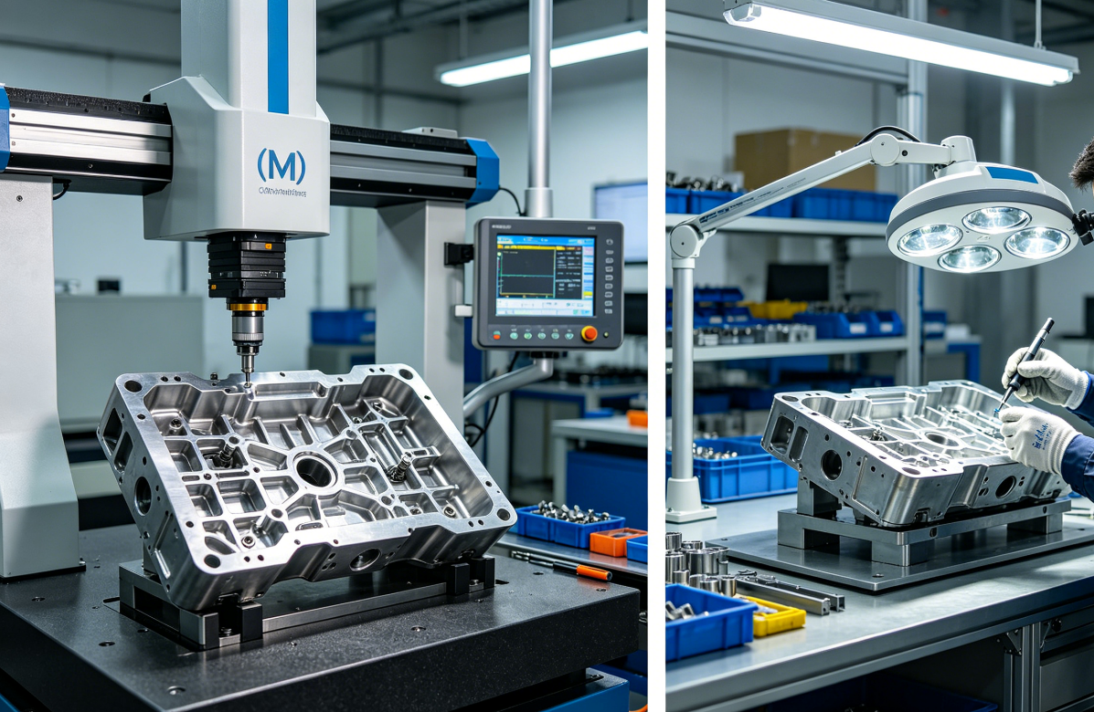
- Full CMM Final Assembly Check: We scan critical OEM assemblies entirely to validate all GD&T position tolerances, overall outer dimensions and sealing flange flatness.
All inspection data gets digitally logged for ISO compliance. We share dimensional drift trends with production crews to tweak cut/bend settings mid-run.
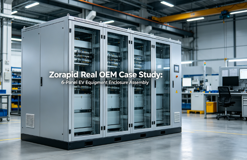
Zorapid Real OEM Case Study: 6-Panel EV Equipment Enclosure Assembly
Client Background
European EV charging OEM, combined 6-piece 304 stainless steel enclosure assembly, strict functional specs: consistent 0.4±0.2mm panel gaps, ±0.1mm PCB mounting hole true position, no interference on door hinge interfaces, batch size 2,500 units.
Original Pre-Optimization Pain Points
- Original drawing used unstructured linear tolerances with long dimension chains, no unified datum frame
- No slotted adjustment holes for secondary mounting brackets
- Average assembly gap variance hit 0.9–1.3mm; 18% of units failed fit testing
- Manual bench assembly without dedicated fixtures caused inconsistent hinge alignment
- Weld thermal distortion warped rear base panel datums, shifting PCB hole patterns
Zorapid Full Tolerance Control Optimization Rollout
- Full DFM tolerance stack-up RSS analysis, restructured all drawings to a single shared primary datum
- Rewrote all mounting hole callouts with True Position GD&T + MMC modifiers
- Added slotted adjustment holes to secondary PCB brackets and hinge mounting plates
- Standardized laser/bend process parameters to tighten single-part variation window
- Built custom 3-2-1 datum assembly fixture for consistent fixturing of all six panels
- Low-heat pulse welding + post-weld flattening to eliminate base panel warpage
- Implemented 3-stage FAI + sub-assembly + final CMM inspection workflow
Final Measurable Results
- Total assembly gap variance reduced to 0.3–0.5mm, fully within client’s 0.4±0.2mm spec
- Assembly non-conformance scrap rate dropped from 18% to 0.7%
- Zero forced rework or manual shimming required across full 2,500-unit batch
- CMM inspection confirmed all critical hole true position tolerances held consistently
- Client eliminated secondary gap sanding labor, cutting total assembly time per unit by 22%
Standard Zorapid Tolerance Control SOP For Combined Sheet Metal Assemblies
Every multi-part sheet metal assembly order follows this fixed 7-step tolerance control process to guarantee consistent fit:
- CAD DFM tolerance stack-up simulation & datum/GD&T design correction
- Realistic sheet metal tolerance specification matching factory process capability
- Add variation-absorbing design features (slots, self-locating tabs, clearance gaps)
- Stabilize cutting, bending, welding & coating to minimize single-part variation
- Fabricate dedicated 3-2-1 datum assembly fixture matched to drawing datums
- Three-stage progressive inspection: single-part FAI → sub-assembly check → full assembly CMM scan
- Digital quality data tracking + closed-loop process adjustment for batch drift correction
We support all standard sheet metal materials for precision assemblies: cold rolled steel, galvanized sheet, 304/316 stainless, 5052/6061 aluminum, with full ISO 9001 and export-compliant inspection reports for global OEM customers.
Quick Troubleshooting Table For Common Assembly Fit Failures
| Visible Assembly Tolerance Issue | Root Stack-Up Cause | Fast Zorapid Fix |
|---|---|---|
| Uneven inconsistent panel gaps | Long unbroken tolerance chains, no shared datums | Restructure drawing to unified primary datum + GD&T true position |
| Mounting bolts cannot align through mating panels | Insufficient hole clearance, no adjustment slots | Add elongated slots to secondary brackets, apply floating fastener GD&T |
| Warped frames & twisting sealing flanges | Weld thermal distortion, unflattened panels | Fixture clamp during welding, post-process roller flattening |
| Hole position drift across multiple panels | Bend springback + uncalibrated laser cutting | Dynamic bend springback compensation, daily laser beam calibration |
| Tight gaps after powder coating | Uncontrolled coating thickness on mating surfaces | Mask datum contact areas, standardize 60–80μm coating film thickness |
| Rotated misaligned sub-assemblies | No 3-2-1 fixture locating, loose manual assembly | Build dedicated datum fixture with hardened locating pins |
FAQ
Can I avoid tolerance stack-up entirely in combined sheet metal assemblies?
Complete elimination is impossible—sheet metal forming and cutting carry inherent minor variation. The goal is controlled stack-up via datums, GD&T and absorption features to keep total drift within functional limits, not zero variation.
Is GD&T mandatory for multi-panel sheet metal assemblies?
Highly recommended for any assembly with critical mounting holes, sealing surfaces or uniform gap requirements. Linear ±X tolerances alone cannot reliably control 3D feature relationships across mating panels, which is why perfectly compliant single parts still fail assembly without GD&T.
How much extra cost does dedicated assembly fixturing add for tolerance control?
For medium/large batches (500+ units), fixture cost amortizes rapidly through eliminated rework, scrap and manual alignment labor. For low-volume prototypes, we use modular adjustable fixture blocks to cut custom tooling overhead while retaining datum control.
Do tighter single-part tolerances automatically fix assembly stack-up?
No. Over-tightening every dimension drastically raises production cost and inspection time, while poorly structured tolerance chains will still accumulate drift. Optimized datums and variation-absorbing design features deliver far better results at lower cost.
Does this tolerance control workflow apply to welded, riveted and bolted sheet metal assemblies alike?
Yes, all core strategies translate across joining methods. Welded frames require extra thermal distortion control, while bolted assemblies benefit most from slotted adjustment hole geometry to absorb stack-up drift.
Final Wrap-Up
Uncontrollable tolerance stack-up in combined sheet metal assemblies doesn’t have to be an accepted manufacturing headache—it stems from early-stage design oversight, unregulated single-part variation, and loose assembly positioning without datum control.
Most sheet metal shops only check single parts, skipping assembly tolerance checks — leaving OEMs stuck with rework fees and shipping delays.
At Zorapid, we build every process around assembly-first tolerance planning: we map stack-up risks during DFM, rework datums & GD&T to cut variation chains, add design margins for dimensional drift, and hold steady positioning with precision fixtures plus multi-step quality checks.
If you’re launching a multi-panel combined sheet metal assembly and want a free tolerance stack-up DFM analysis to eliminate fit failures and scrap, send your STEP/DXF CAD files to our sheet metal engineering team for a no-obligation optimized quote today.