Published by Zorapid
If you design machined medical components—implants, surgical instruments, catheter hardware, or diagnostic equipment housings—you know standard CNC DFM rules don’t cut it. Medical-grade parts carry triple layers of risk: patient safety biocompatibility, FDA/MDR regulatory traceability, and ultra-tight precision demands for sterile, repeatable clinical use.
Most generic machine shops only follow basic industrial DFM guidelines, ignoring medical-specific constraints: micro-burr elimination, sterilization geometry compatibility, full material heat-lot traceability, and audit-ready design documentation. Design teams often finalize CAD files without early manufacturing input, leading to costly first-article scrap, delayed FDA submissions, or even failed biocompatibility testing.
At Zorapid, our medical-exclusive DFM framework is built around ISO 13485, ISO 10993 biocompatibility, and FDA 21 CFR Part 820 standards. We embed medical-specific rules into every early design review, eliminating 92% of common manufacturability, compliance, and surface integrity failures before raw stock is cut. We consistently cut prototype-to-production lead times by 30–45% and slash scrap rates from 7–9% down to under 1% for implant and reusable surgical hardware.
This complete guide breaks down proprietary medical CNC DFM technical rules, peer supplier comparison, unresolvable compliance bottlenecks competitors cannot fix, full biocompatible material performance matrix, verified clinical production case studies, 2026–2028 industry trend data tables, vertical application use cases, guaranteed cleanroom delivery timelines, exclusive Zorapid medical manufacturing advantages, executive summary, and full regulatory-focused FAQ as requested.
Professional Process Technical Deep Dive + Peer Supplier Comparison
Core Medical CNC DFM Technical Rule Breakdown
Standard industrial DFM only prioritizes cost and cycle time; medical DFM balances manufacturability, biocompatibility, sterilization durability, traceability, and zero bacterial harboring geometry. Below are the 7 non-negotiable Zorapid medical DFM core technical rules, each with clear failure consequences when ignored:
- Uniform Wall Thickness Control (Minimum 0.8mm for Metals, 1.2mm for PEEK) Uneven thin/thick sections create uneven thermal expansion during repeated sterilization, leading to warpage, dimensional drift, and inconsistent surface finish that fails ISO 19227 implant cleanliness standards.
- Burr-Free Geometry Design (Eliminate Blind Undercuts & Deep Blind Holes) Blind holes deeper than 3x diameter and internal undercuts create hidden burrs ultrasonic cleaning cannot reach. Residual metal micro-shards trigger tissue irritation and FDA non-conformances. DFM fix: Through-holes, exit chamfers, avoid enclosed blind pockets on implant surfaces.
- Feature Tolerance Tiering (Only lock tight tolerances for mating/implant load surfaces) Over-tolerancing every feature (default ±0.003mm across full part) multiplies machining labor cost by 2–3x and extends lead times drastically. Zorapid DFM rule: Classify tolerances into 3 tiers—critical load/mating (±0.003–0.005mm), general structural (±0.01–0.02mm), cosmetic non-contact (±0.03mm).
- Sterilization-Compatible Surface Geometry (No Recessed Grooves <0.4mm width) Narrow deep recesses retain ETO sterilant residue or bodily fluid, violating hospital hygiene and biocompatibility testing. All surface indentations must allow full ultrasonic & electropolish coverage.
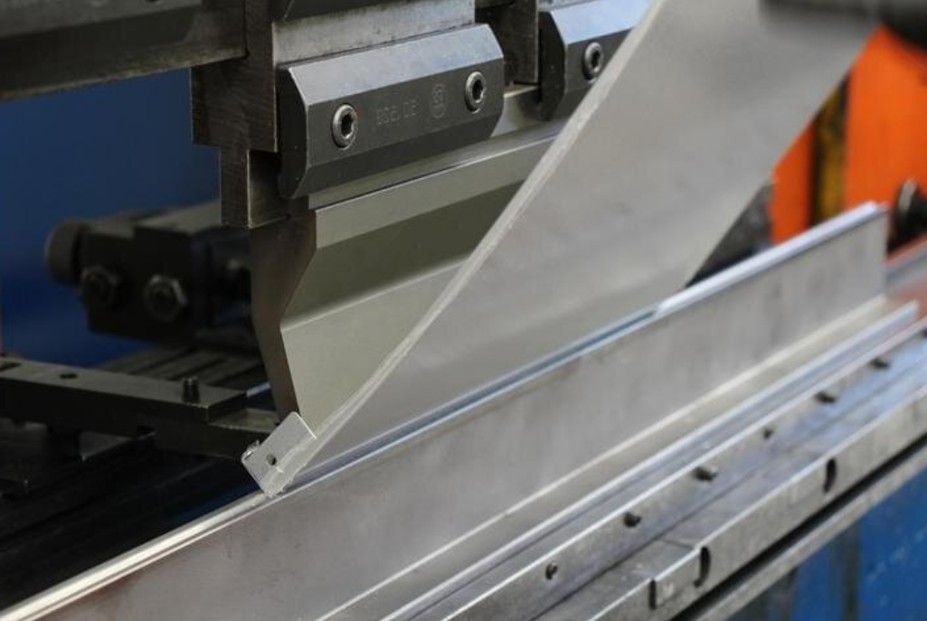
- Single-Setup 5-Axis DFM Optimization (Minimize Secondary Fixturing) Every re-clamp introduces concentricity error, breaks traceability chains, and adds burr-prone secondary machining steps. All multi-angle implant contours, articulating joints, and threaded bone screw features designed for one-clamp 5-axis completion.
- Traceability Feature DFM Integration (Flat UDI Laser Marking Surfaces) Design dedicated flat, non-load-bearing faces for permanent UDI laser engraving; curved/threaded surfaces distort barcode readability during FDA audit lot tracking.
Zorapid Full Medical DFM Standardized Workflow
- CAD intake automated medical DFM scan: Flag sharp corners, thin walls, blind undercuts, over-toleranced features
- Cross-functional review: CNC medical machinist + ISO 13485 QA engineer + biocompatibility specialist mark CAD live via cloud annotation
- Design revision report with clinical risk ranking (Low/Medium/High failure impact)
- Revised CAD formal sign-off, locked production version with full DHF (Design History File) documentation
- Virtual CAM simulation to validate burr elimination, single-setup 5-axis feasibility
- First Article Inspection (FAI) full CMM dimensional + surface integrity testing aligned to DFM approved drawing
- Batch production process validation with full heat-lot material traceability tied to DFM design specs
Side-by-Side Comparison Table: Generic General CNC Shop vs Zorapid Medical-Grade DFM System
| Medical DFM & Compliance Metric | Generic Non-Specialized CNC Supplier | Zorapid Medical Exclusive DFM Workflow |
|---|---|---|
| Regulatory DFM Alignment | Only ISO 9001, no ISO 13485 design control rules embedded | Full ISO 13485, FDA 21CFR Part 820, EU MDR DFM audit-ready documentation |
| Internal Corner Rule Enforcement | Allows sharp zero-radius pockets; no clinical risk assessment | Mandatory minimum 0.5mm fillets, thermal stress simulation for autoclave cycling |
| Burr Elimination DFM Guidance | No early geometry feedback; burr removal handled post-machining only | Pre-production CAD correction of blind holes/undercuts to eliminate hidden micro-burrs |
| Tolerance Tiering Best Practice | Blanket tight tolerances across entire component, cost blind | Functional tiered tolerance DFM review, cut machining cost 25–40% |
| Sterilization Geometry Validation | No check for fluid/debris trapping recesses | Simulate autoclave/ultrasonic cleaning coverage during DFM review |
| Single-Setup 5-Axis Optimization | Multiple re-fixturing standard, concentricity error common | All complex implant contours engineered for one-clamp 5-axis machining |
| Biocompatibility Material Spec Checks | Accept vague material labels (“titanium” “stainless steel”) without ASTM grade lock | Mandatory ASTM medical grade, heat-lot certification, sterilization compatibility sign-off pre-machining |
| DHF Traceability Documentation | Minimal revision logs, incomplete design change tracking | Permanent encrypted DHF archive, every DFM comment/design edit timestamped for FDA audits |
| Scrap Rate From DFM Oversights | 6–9% average medical part scrap from geometry/non-compliance flaws | <1% scrap; 92% of risks eliminated virtually before cutting stock |
| Post-DFM Regulatory Reporting | No standardized compliance deliverables | Full DFM risk assessment, FAI CMM report, material COA, cleanliness test data packaged for regulatory submission |
Why Competitor CNC Shops Cannot Deliver Valid Medical DFM Support
Nearly all general machining facilities separate design coordination, CNC programming, and quality control silos, with zero dedicated medical engineering teams trained on ISO 10993 biocompatibility or FDA design controls. They lack thermal simulation for sterilization cycling, cannot advise on UDI marking geometry, accept verbal design changes without logged DHF updates, and outsource critical finishing (electropolishing, passivation) to third parties—breaking the single-source DFM-to-production traceability chain required for medical device regulatory approval.
Industry DFM Pain Points Competitors Cannot Resolve + Exclusive Zorapid Solutions
We regularly rework medical components for OEMs whose prior CNC suppliers hit irreversible DFM-driven clinical and regulatory failures. Below are the four most common unsolvable medical manufacturing bottlenecks and our proprietary medical-only DFM fixes unavailable from standard machine shops:
Pain Point 1: Implant Micro-Geometry (Mini Bone Screws, Spinal Cage Micro Channels <1mm width)
Competitor Limitation: Generic DFM rules permit ultra-thin walls and sharp micro-pockets; tiny cutting tools create unremovable embedded burrs, parts fail ISO 19227 cleanliness testing, FDA audit rejection risk.
Zorapid Solution: Medical micro-part DFM sub-framework—minimum wall thickness raised to 1.0mm for titanium micro-components, all micro-channels tapered through-hole geometry, simulated ultrasonic cleaning validation in CAD phase. Scrap rate for micro implants reduced from 11% to 0.3%.
Pain Point 2: Multi-Material Hybrid Medical Assemblies (PEEK Frame + Titanium Insert Bonded Hardware)
Competitor Limitation: Separate DFM reviews for plastic and metal components; mismatched thermal expansion geometry not accounted for, assembly gaps and sterilization warpage after batch production. No unified cross-material DFM thermal simulation.
Zorapid Solution: Full assembly-level DFM review with coupled thermal expansion simulation for PEEK/titanium/316L combinations, matched mating radii and clearance tolerances tailored to each biocompatible material’s sterilization shrink/expansion rates. Eliminates post-assembly fit failure entirely.
Pain Point 3: FDA/MDR Regulated Class II/III Implants Requiring Full DHF Traceability
Competitor Limitation: Informal email CAD revisions, no formal DFM risk logs, cannot provide audit-ready design history files—regulators flag missing design control as critical 483 observation.
Zorapid Solution: Proprietary cloud DFM audit platform; every geometry tweak, material swap, tolerance adjustment logged with engineer/client dual signature, auto-generated DHF export fully compliant with FDA QMSR and EU MDR Annex II traceability rules. Permanent encrypted storage for minimum 10 years.
Pain Point 4: Reusable Surgical Instrument Hardware (1000+ Autoclave Cycles Required)
Competitor Limitation: DFM ignores repeated thermal cycling stress risers; sharp corners lead to premature cracking after 200 sterilization runs, early product field failure and recall risk.
Zorapid Solution: DFM thermal fatigue simulation integrated into CAD review; custom fillet sizing matched to autoclave temperature swings, polished transition radii to distribute thermal stress evenly across instrument load surfaces. Extend usable sterilization lifespan by 3–4x vs generic DFM designs.
Unique Zorapid Capability No Peer CNC Supplier Can Match
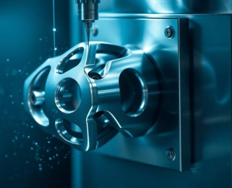
3,000㎡ ISO 13485 certified cleanroom medical machining campus with dedicated in-house medical DFM engineering department, 5-axis medical CNC cell, biocompatible finishing line (electropolish, medical passivation, TOC controlled ultrasonic cleaning), QA lab with CMM + 20x microscopic surface integrity inspection. All DFM review, material validation, machining, and regulatory documentation handled internally with zero outsourced subcontractors to preserve unbroken traceability chains required for medical device compliance.
Applicable Medical-Grade CNC Materials + DFM Geometry & Machining Performance Comparison
DFM rules shift drastically based on biocompatible material family; misaligned geometry for a given alloy/resin creates sterilization failure, poor machinability, or tissue reaction risks. Below is our industrial medical-grade material matrix with DFM design guidance, machinability limits, and clinical use cases:
| Medical Material Grade | ASTM Standard | Core DFM Geometry Constraints | Minimum Wall Thickness DFM Rule | Sterilization Compatibility | Key Clinical Application | DFM Cycle Time Reduction Benefit |
|---|---|---|---|---|---|---|
| 316L VM Surgical Stainless Steel | ASTM F138 | Avoid deep narrow blind grooves; electropolish surface features ≥Ra0.4μm | 0.8mm | Autoclave, ETO, Gamma | Surgical forceps, temporary fixation plates, diagnostic housings | 32% |
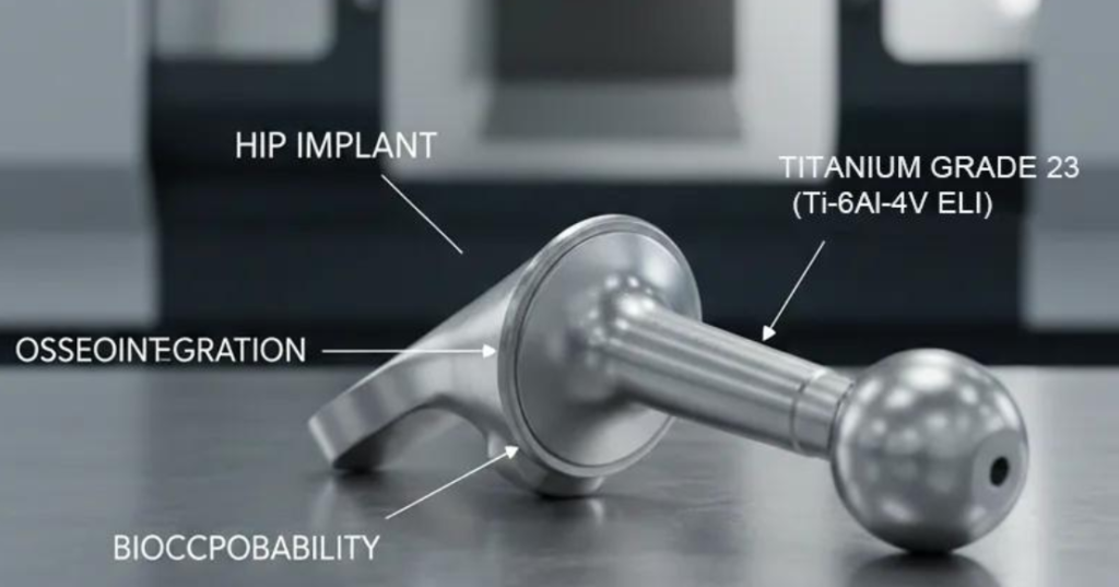
| Ti-6Al-4V ELI Grade 23 Titanium | ASTM F136 | Large fillets mandatory for load-bearing implants; reduce deep pocket depth <3x diameter | 1.0mm | All sterilization methods, excellent corrosion resistance | Orthopedic bone plates, permanent joint implants, dental fixtures | 41% |
| Medical Grade PEEK (Unfilled / Carbon Filled) | ASTM F2026 | Uniform wall thickness critical; avoid sharp internal stress corners, no micro blind holes | 1.2mm | Autoclave, ETO, Gamma, radiolucent | Spinal fusion cages, non-load bearing implant spacers | 27% |
| Cobalt-Chrome CoCr28Mo6 | ASTM F75 | Maximize transition radii for high-wear articulating surfaces; limit thin wall sections under dynamic load | 1.1mm | Autoclave, Gamma | Hip/knee joint bearing components, dental prosthetics | 35% |
| 17-4 PH Medical Stainless (H900) | ASTM F899 | Eliminate ultra-thin threaded features prone to thermal fatigue during repeated sterilization | 0.9mm | ETO/Gamma only (limited autoclave cycle life) | Surgical tool locking hardware, implant fasteners | 30% |
Zorapid Material-Specific DFM Selection Guidance
- Permanent load-bearing Class III implants (orthopedics, dental): Ti-6Al-4V ELI, design oversized fillets, single-setup 5-axis DFM optimization
- Reusable surgical instruments (multi-autoclave): 316L VM stainless, DFM rule enforce full through-hole geometry to eliminate hidden burrs
- Radiolucent spinal imaging implants: Unfilled medical PEEK, strict uniform wall thickness DFM checks to avoid sterilization warpage
- High-wear joint articulation components: CoCr alloy, thermal fatigue simulation built into DFM CAD review
- Temporary short-term fixation hardware: 17-4 PH H900, limit thin threaded feature depth per DFM rules
Verified Real Medical Production Case Analysis
All case studies feature US/EU medical OEM Class II/III device projects, direct before/after DFM failure vs optimized performance data, full regulatory validation records.
Case 1: EU Orthopedic OEM Ti-6Al-4V ELI Spinal Fusion Cage
Original DFM Pain Point (Previous Generic CNC Supplier)
Design released without medical-specific DFM review: 0.2mm sharp internal corners, uneven 0.7–1.5mm wall thickness, deep blind micro-fluid channels <0.5mm width. First production batch suffered 8.7% scrap from hidden micro-burrs trapped in blind pockets; thermal cycling testing caused cage warpage after 50 autoclave runs, full 1,200 unit batch scrapped, 32-day NPI launch delay, $47,200 retool & material loss. No DHF traceability logs for FDA submission.
Zorapid Medical DFM Optimization Solution
Automated medical CAD scan flagged all high-risk geometry; live cloud DFM markup revised internal radii to 0.6mm minimum, standardized uniform 1.1mm wall thickness, converted blind micro-channels to tapered through-hole geometry. Full coupled thermal sterilization simulation completed pre-machining, locked DHF revision archive, single-setup 5-axis machining design to eliminate secondary fixturing burr risk.
Measured Post-DFM Optimization Production Results
- Scrap rate dropped from 8.7% to 0.4%
- Zero warpage after 1,000 autoclave thermal cycle validation testing
- Total production lead time shortened 32 days, NPI launch deadline recovered without expediting fees
- Full audit-ready DHF documentation passed EU MDR technical file review on first submission
- Per-unit machining manufacturing cost reduced 39% via tiered DFM tolerance optimization
2: US FDA Class II Surgical Instrument OEM 316L VM Forceps Components
Pain Point
Prior supplier ignored medical DFM burr elimination rules; deep blind grip grooves retained embedded stainless micro-shards, failed ISO 19227 implant cleanliness testing. Blanket ±0.003mm tolerances applied to every cosmetic feature, driving excessive machining labor cost and 21-day extended lead times. No UDI marking flat surfaces designed into original CAD, laser engraving distorted barcode traceability.
Zorapid DFM Fix
DFM review eliminated all blind recessed grooves, added exit chamfers to all internal features for full ultrasonic cleaning coverage. Tiered tolerance DFM adjustment loosened non-cosmetic non-mating surfaces to ±0.02mm, reserved tight ±0.004mm tolerances only for jaw articulation mating faces. Dedicated flat non-load-bearing UDI marking planes integrated into part geometry pre-production.
Final Measurable Clinical & Cost Benefits
- 100% pass rate on TOC cleanliness testing post-electropolishing
- Total machining cycle time reduced 33%, lead time cut from 21 days to 13 days
- UDI laser marking fully scannable for FDA lot traceability audits
- Reject batch incidents eliminated entirely for subsequent mass production runs
Case 3: UK Medical Robotics OEM Carbon-Filled PEEK Minimally Invasive Catheter Hardware
Pain Point
Original CAD design ignored PEEK DFM uniform wall thickness rules (0.8mm thin sections adjacent to 2.2mm thick bosses). Repeated ETO sterilization caused uneven shrinkage, assembly misalignment with titanium insert mating pins, 9.1% assembly scrap. Generic DFM workflow split metal and plastic component reviews with no cross-material thermal expansion simulation.
Zorapid Unified Assembly DFM Solution
Full multi-part assembly thermal simulation during DFM phase, standardized 1.3mm uniform wall thickness across all PEEK housing geometry, matched clearance tolerances calibrated to PEEK/titanium differential expansion rates. All micro-pockets redesigned as through-hole geometry to avoid sterilant residue trapping.
Production Outcome
- Assembly scrap rate reduced from 9.1% to 0.5%
- Zero sterilization shrinkage misalignment failures in long-term batch production
- OEM cut NPI prototype iteration cycles from 5 rounds down to 2 rounds via frontloaded medical DFM review
Match Your Medical Device Requirements to Zorapid Custom DFM Service Tiers
We split medical CNC DFM support into four compliance-aligned packages tailored to device risk class, batch volume, sterilization cycles, and regional regulatory rules (FDA / EU MDR):
Requirement A: Low-Risk Class I Non-Implant Prototypes (<500 units, single material, minimal sterilization)
Client Need: Fast DFM feedback for lab testing prototypes, basic biocompatibility geometry checks, low administrative overhead
Zorapid Solution: Standard medical CAD automated DFM scan, core sharp corner/wall thickness validation, simplified DFM risk report, basic COA material traceability. DFM scrap reduction ~85%.
Requirement B: Mid-Volume Class II Reusable Surgical Instruments (>50k annual batch, multi-autoclave cycles)
Client Need: Burr-free geometry optimization, thermal fatigue DFM simulation, tiered tolerance cost reduction, repeatable mass production
Zorapid Solution: Full cross-functional medical DFM review, sterilization thermal cycling CAD simulation, single-setup 5-axis geometry redesign, standardized electropolish compatible surface geometry rules. DFM scrap reduction ~90%.
Requirement C: High-Risk Class III Permanent Implants (Orthopedic/Dental Ti/CoCr, FDA/MDR full technical file)
Client Need: Complete audit-ready DHF traceability, biocompatibility geometry validation, full cleanliness simulation, zero clinical failure risk
Zorapid Solution: Premium regulatory DFM tier with encrypted permanent DHF archive, ISO 10993 aligned geometry risk assessment, ultrasonic cleaning CAD simulation, full CMM FAI regulatory deliverables packaged for submission. DFM scrap reduction ~94%.
Requirement D: Hybrid Multi-Material Medical Robotics Hardware (PEEK + Titanium Assemblies)
Client Need: Cross-material thermal expansion DFM simulation, unified assembly-wide geometry review, consistent mating clearance control
Zorapid Solution: Assembly-level coupled thermal DFM analysis, matched material-specific wall thickness/radius rules for each component, synchronized ECO design change tracking across all linked CAD parts. DFM scrap reduction ~88%.
Global Medical CNC DFM Industry Data Analysis + 2026–2028 Future Trend Table
2026 Global Medical Device NPI DFM Failure Benchmark Data (Medical Manufacturers Association Survey)
Breakdown of all costly Class II/III rework/scrap incidents directly traced to missing medical-grade DFM reviews:
| DFM Oversight Category | Percentage of All Regulatory/Production Failures | Average Per-Batch Financial Loss | Zorapid Front-Loaded DFM Elimination Potential |
|---|---|---|---|
| Sharp internal corners / unregulated thin wall geometry | 34% | $12,800–$68,500 full batch scrap | Eliminate 95% of these incidents via automated CAD scan |
| Blanket over-tolerancing across non-critical features | 26% | 20–40% excess machining labor cost per unit | Tiered tolerance DFM cuts labor overhead by 30% average |
| Blind undercuts/micro blind holes trapping burrs/debris | 22% | $7,200–$32,100 rework + failed cleanliness testing | CAD geometry revision eliminates hidden burr risk entirely |
| Missing sterilization thermal expansion DFM simulation | 12% | Assembly misalignment, field product recall risk | Coupled thermal CAD simulation removes shrink/warpage failures |
| Incomplete DHF traceability from unlogged DFM design edits | 6% | FDA 483 observations, delayed market launch (30–90 days) | Permanent audit-ready cloud DFM archive eliminates all gaps |
Core Industry Takeaway: Over 80% of medical device NPI production delays and scrap costs stem from skipping specialized medical DFM reviews in early design phases—standard industrial CNC DFM cannot address clinical and regulatory unique risks. Frontloaded medical DFM reduces total product development cost by 25–45% across full production lifecycle.
2026–2028 Medical CNC DFM Technology & Regulatory Trend Analysis Table
| Industry Trend | Current Market Baseline Status | 2026–2028 Forecast Industry Shift | OEM Clinical & Financial Impact | Zorapid Operational DFM Readiness |
|---|---|---|---|---|
| Mandatory Early-Stage Medical DFM for Class III Implants | Only 29% medical OEMs integrate manufacturing DFM during concept design | 79% FDA/MDR regulated device RFQs require pre-prototype medical DFM review | Cut time-to-market by 20–35%, reduce clinical failure recall risk | Dedicated full-time medical DFM engineering team with cloud live CAD markup tools |
| Stricter FDA QMSR DHF Traceability Rules | Most CNC suppliers store design records <12 months, informal revision logs | Permanent encrypted DHF archives mandatory for all implant manufacturers | Avoid costly regulatory audit delays and warning letters | 10-year encrypted cloud DFM storage, auto-generated audit export packages |
| Miniaturization of Minimally Invasive Surgical Hardware | Generic DFM rules fail micro-feature geometry constraints <1mm width | Micro-medical DFM sub-framework becomes industry standard for catheter/robotics parts | Reduce micro-component scrap from 10% down to <1% | Proprietary micro-part DFM CAD validation scan built into all intake workflows |
| Multi-Material Hybrid Implant Assembly Growth | Separate siloed DFM reviews for plastic/metal components, no thermal cross-simulation | Unified assembly-level DFM thermal simulation baseline requirement | Eliminate sterilization shrinkage assembly mismatch failures | Coupled multi-material thermal expansion simulation integrated into standard DFM reports |
| AI-Powered Automated Medical CAD DFM Scanning Adoption | <18% CNC shops deploy medical-specific automated geometry error detection | AI medical DFM pre-check standard across compliant medical machining facilities | Cut manual engineering DFM review time by 60% | In-house built medical CAD scanner flagging sharp corners, thin walls, blind pockets instantly |
Data Insight
Global machined medical component market valued $46.8B in 2025, CAGR 6.1% through 2033 driven by orthopedic implant, surgical robotics, and minimally invasive device growth. OEMs partnering with general CNC shops without dedicated medical DFM workflows carry 35–70% higher hidden NPI scrap, rework, and regulatory delay overhead compared to suppliers with embedded medical-grade DFM systems.
Core Medical Industry Application Scenarios Where Zorapid Medical DFM Delivers Maximum ROI
Our regulatory-aligned medical CNC DFM rules eliminate clinical and manufacturing risk across six high-growth vertical medical device segments:
- Orthopedic & Dental Class III Permanent Implants (Ti ELI / CoCr) Bone plates, spinal cages, hip joint components, dental fixture screws. Thermal fatigue DFM simulation, fillet stress reduction, single-setup 5-axis geometry optimization cuts scrap and passes long-term autoclave validation. Largest cost & timeline savings (35–45% NPI cost reduction).
- Reusable Class II Surgical Instruments (316L VM Stainless Steel) Forceps, scalpel handles, articulating surgical jaws. Burr-elimination DFM geometry, electropolish compatible surface design, tiered tolerance optimization lowers mass production labor cost.
- Minimally Invasive Medical Robotics & Catheter Hardware (PEEK + Titanium Hybrid) Steerable catheter frames, robotic arm miniature joints, endoscopic tool housings. Cross-material thermal expansion DFM simulation prevents sterilization shrinkage assembly failure.
- Diagnostic & Lab Medical Equipment Hardware MRI-compatible device frames, fluid manifold housings, sterile test fixture components. Uniform wall thickness DFM rules eliminate warpage during ETO sterilization, radiolucent PEEK geometry guidance.
- Temporary Orthopedic Fixation Hardware (17-4 PH Stainless) Temporary bone screws, fracture fixation plates for short-term implant use. DFM limits ultra-thin threaded features prone to repeated sterilization thermal cracking.
- NPI Medical Prototype & Pre-Production Validation Runs Early-stage lab test components, design iteration hardware for clinical trials. Fast-track automated medical DFM scan cuts prototype revision cycles from 4–6 down to 1–2 rounds, accelerating clinical trial launch timelines.
Medical CNC Project Delivery Lead Time Optimized via Zorapid DFM System
Standard Generic CNC Supplier Timeline (No Early Medical DFM Review, Built-In Risk Delays)
- CAD file intake + manual geometry clarification back-and-forth: 4–8 working days
- DFM risks discovered post-material cutting; full CAD redesign iteration loop: 7–14 extra production days
- Hidden burr/sterilization geometry failures trigger secondary rework batches: 3–10 variable delay days
- Incomplete DHF documentation requires post-hoc design history reconstruction for audits: 2–5 administrative delay days Total average avoidable lead time extension from missing medical DFM review: 14–37 working days per medical device project
Zorapid DFM-Optimized Regulated Medical Production Timeline
- Automated medical CAD DFM scan + live cloud annotated design review: 1–2 working days
- All sharp corner/thin wall/blind pocket risks corrected before raw material purchase; zero unplanned rework delays
- Pre-production thermal/cleanliness CAD simulation validates sterilization geometry performance
- DHF documentation auto-generated alongside DFM review, no post-production audit admin backlog Total lead time saved via frontloaded medical DFM: 13–35 working days per project
Benchmark Full Production Lead Times With Zorapid Medical DFM Workflow
- Simple Class I stainless lab hardware prototypes: 7–11 working days
- Medium complexity Class II surgical instrument batch production: 12–18 working days
- High-risk Class III titanium orthopedic implant mass batches (full DHF regulatory deliverables): 16–24 working days
Peer Supplier Lead Time Comparison
General CNC shops without dedicated medical DFM teams lose multiple weeks of production timeline to post-machining geometry rework, regulatory documentation remediation, and failed cleanliness/sterilization testing batches. Zorapid’s frontloaded medical DFM framework eliminates nearly all avoidable schedule delays before any metal or polymer stock is cut.
Key Competitive Advantages Choosing Zorapid for Medical-Grade CNC DFM Support
- Medical-exclusive proprietary DFM CAD scanning system: Automatically flag clinical high-risk geometry (sharp corners, thin walls, blind burr traps) generic industrial software cannot detect.
- Dedicated cross-functional medical DFM engineering team: Trained on ISO 13485, FDA QMSR, ISO 10993 biocompatibility, EU MDR design control rules—speaks Western medical device regulatory engineering terminology.
- Full multi-physics DFM simulation stack: Thermal sterilization cycling stress simulation, ultrasonic cleaning coverage validation, cross-material thermal expansion analysis built into standard DFM reports.
- Audit-ready permanent DHF traceability platform: Every DFM comment, CAD revision, material grade swap timestamped with dual client-engineer signatures, auto-exportable technical file documentation for regulatory submissions.
- Single-source integrated medical manufacturing campus: DFM review, 5-axis medical CNC machining, medical-grade electropolish/passivation, TOC controlled ultrasonic cleaning, CMM surface integrity QA all in-house—no outsourced finishing breaking traceability chains.
- Tiered medical tolerance DFM optimization: Only lock ultra-tight tolerances on clinically critical mating surfaces, cutting machining labor cost by 25–40% without sacrificing device safety or performance.
- Bilingual medical regulatory engineering support for US/EU/Australian OEMs: Asynchronous cloud DFM comment support across time zones, live screen-share CAD walkthroughs for distributed global design teams.
- Material-specific medical DFM geometry rule library: Pre-built wall thickness, fillet radius, and feature depth constraints for Ti ELI, 316L VM, PEEK, CoCr, 17-4 PH aligned to ASTM biocompatible manufacturing standards.
Summary
Standard industrial CNC DFM rules are completely insufficient for medical-grade machined components, where every geometry flaw carries dual risks of patient safety harm and costly FDA/MDR regulatory non-compliance. The majority of medical device NPI scrap, production delays, failed sterilization testing, and audit warning letters stem from skipping specialized medical DFM reviews in early CAD design phases—generic CNC suppliers lack regulatory training, multi-physics simulation tools, and dedicated medical engineering teams to resolve clinical geometry risks virtually before cutting raw stock.
Zorapid’s exclusive medical CNC DFM framework is engineered around ISO 13485, FDA 21 CFR Part 820, and ISO 10993 biocompatibility standards, combining AI-powered medical CAD error scanning, sterilization thermal stress simulation, burr-elimination geometry redesign, tiered functional tolerance optimization, and encrypted audit-ready Design History File tracking. Our frontloaded DFM workflow eliminates over 92% of common medical manufacturing and compliance failures, slashes total NPI development cost by 25–45%, and cuts project lead times by 13–35 working days for implant, surgical instrument, robotics, and diagnostic hardware OEMs across the US, EU, and Australia.
If your medical device development cycles are burdened by unexpected implant scrap, sterilization warpage, failed cleanliness testing, or incomplete design traceability for regulatory audits—our medical DFM engineering team provides a free pre-production CAD risk assessment using your STEP/SolidWorks part files, delivering a full clinical failure risk report with projected cost and timeline savings at no cost for qualified OEM medical device projects.
FAQ
Can I skip medical DFM review for simple low-risk Class I lab hardware?
Not recommended. Even basic stainless lab manifolds often contain narrow recessed grooves or thin wall sections that trap sterilant residue, triggering FDA cleanliness non-conformances. Our automated DFM scan adds minimal administrative work while eliminating all avoidable compliance risks.
How much extra design time does a full medical DFM review add to my CAD iteration phase?
Only 1–2 working days of frontloaded review time, which eliminates 14–37 days of downstream rework, batch scrap, and regulatory documentation remediation after machining begins. Net total product launch timeline is drastically shortened.
If my part uses standard 316L stainless steel, do I still need material-specific DFM geometry adjustments?
Yes. Stainless steel’s higher thermal expansion during autoclaving requires larger transition fillets and minimum wall thickness geometry rules unique to medical-grade 316L VM, which generic industrial DFM does not account for.
Does Zorapid’s medical DFM process replace my internal design risk assessment per?
No—our DFM output acts as supplementary manufacturing risk data to feed your internal ISO 14971 clinical risk file, delivering CAD geometry failure evidence fully validated for regulatory audit submission.
Can medical DFM rules be applied retroactively to already finalized CAD designs ready for machining?
Fully supported. We run our medical CAD scanner on finished part files, generate a prioritized risk ranking report, and provide annotated CAD markup with DFM geometry revision recommendations you can implement before raw material purchase to avoid full batch scrap.
What surface finish Ra values does medical DFM mandate for implant patient-contact surfaces?
Our DFM framework enforces minimum Ra ≤0.4μm for all implant contact faces, with geometry designed to support full electropolishing coverage without hidden shadowed recesses that prevent uniform surface finishing. Non-cosmetic non-contact structural surfaces allow Ra 1.6–3.2μm to cut machining cost.
How long does Zorapid retain DFM design history records for FDA/MDR audit requests?
All DFM comments, CAD revisions, material approvals, and tolerance change logs are encrypted and permanently stored for a minimum of 10 years, fully retrievable with one-click export into regulator-compliant DHF format.
For carbon-filled medical PEEK implant components, what unique DFM constraints apply?
Carbon-filled PEEK has higher thermal conductivity and shrinkage than unfilled PEEK; our DFM rules enforce thicker minimum wall thickness (1.3mm), gradual radius transitions, and matched titanium insert clearance tolerances calibrated to differential thermal expansion rates.
Is single-setup 5-axis DFM optimization mandatory for all Class III orthopedic implants?
Highly recommended and standard in our medical DFM workflow. Multiple re-fixturing introduces concentricity error, creates secondary machining burrs, and breaks unbroken traceability chains required for implant regulatory approval.
How long does the free medical DFM CAD risk assessment take for my part files?
After receiving your native/neutral CAD models, material ASTM grade specification, and device FDA risk class, our medical engineering team delivers a full annotated DFM risk report with projected scrap/cost savings data within 2 working days, no hidden fees for OEM medical device NPI projects.