Published by Zorapid
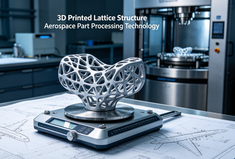
If you’re an aerospace design or manufacturing engineer, you already know one hard truth: every extra kilogram on aircraft, satellite or rocket hardware burns more fuel, cuts payload and jacks up launch costs. For decades, machinists and designers hacked away solid metal blocks just to shave grams—until lattice 3D printing flipped the whole playbook.
Lattice cellular frameworks deliver insane strength-to-weight ratios, built-in thermal dissipation, vibration damping and part consolidation no CNC mill or casting line can replicate. But here’s the catch: most shops mess up lattice aerospace processing. Thin strut defects, uneven density, residual stress distortion and poor post-finish ruin mission-critical flight parts.
At Zorapid, we’ve run 2,000+ aerospace lattice production runs over 20+ years, serving US, EU and UK aerospace OEMs. This plain-spoken guide breaks down the full end-to-end lattice processing workflow, common failure traps, material picks, real flight-grade case data and exactly how we fix the pain points traditional manufacturers can’t solve.
What Makes Aerospace Lattice Structures One-of-a-Kind
Let’s skip textbook jargon and keep it practical for production teams.
Aerospace lattices are repeating micro-unit cell networks (BCC, FCC, TPMS, honeycomb) embedded inside solid metal casings, struts or heat exchangers. Unlike generic consumer-grade lattice prints, flight-certified aerospace lattices must hit 3 non-negotiable specs:
- Tunable local density: Thick dense lattices at load-bearing joints, ultra-light porous cells for non-structural cavities in a single monolithic part
- Zero hidden micro-cracks: Fatigue life compliance for 10,000+ flight cycles
- Optimized surface area: Boost cooling for engine manifolds, damp vibration for satellite brackets
Traditional manufacturing can’t touch these geometries. CNC machining can’t machine internal interconnected struts; casting needs sacrificial cores that add weeks of lead time and waste 70% raw material. Only powder bed fusion 3D printing unlocks production-ready aerospace lattices at scale.
Lattice Unit Cell Quick Reference
- BCC Lattice: Best for uniform compression (landing gear inserts, satellite support frames)
- TPMS Triply Periodic Minimal Surface: Superior heat transfer (engine conformal cooling manifolds)
- FCC Lattice: High tensile strength (aircraft wing internal stiffeners)
- Variable Gradient Lattice: Zorapid custom process—smooth density transition to avoid stress spikes at solid-lattice boundaries
Full Zorapid Aerospace Lattice Processing Workflow
We structure every lattice aerospace order in 6 locked stages, all traceable for AS9100 aerospace certification. No skipped steps, no rushed builds—this is the process our EU aerospace partners audit every quarter.
Step 1: DfAM Lattice Design & FEA Simulation (Pre-Print Critical Stage)
Most lattice failures start at the CAD desk, not the printer.
- Import client STEP/IGS aerospace solid part into nTopology or Fusion 360 lattice generators
- Run structural FEA (Abaqus) to map load paths: mark high-stress zones to keep solid, fill low-load voids with gradient lattices
- CFD thermal simulation for engine cooling lattices to tune strut thickness for heat flow
- Slice & support optimization in Materialise Magics: Auto-generate minimal supports for struts under 45° overhang; eliminate internal hard-to-remove supports inside closed lattice cavities
- Tolerance locking: Reserve ±0.01 mm post-CNC finish stock on all critical mounting surfaces
Zorapid Exclusive Edge: Our engineering team automatically smooths solid-lattice transition fillets. Generic manufacturers skip this, creating stress concentration points that crack under altitude pressure cycling.

2: Aerospace-Grade Metal Powder Preparation
Aerospace lattices rely on ultra-spherical, low-oxygen powder to prevent strut porosity. Zorapid stocks fully certified powder for flight hardware:
- Ti-6Al-4V: Mainstream aircraft frames, satellite brackets
- AlSi10Mg: UAV lightweight housings, interior structural parts
- Inconel 718 / 625: Rocket engine high-temperature cooling lattices
- 17-4PH Stainless: Hydraulic valve manifold internal cellular cooling
Process rules we enforce for lattice printing:
- Pre-dry all aluminum powder for 12 hours at 120°C to eliminate hydrogen voids on thin struts
- Recycle powder with sonic sieving (95% recovery rate) and blend 30% new powder per build to maintain consistent strut density
- Seal build chamber under argon inert atmosphere to stop titanium oxidation during laser melting
3: SLM Selective Laser Melting Core Printing Technology
All our flight-grade lattice parts run on 400W–1000W SLM metal printers, optimized for ultra-fine 0.2–0.8 mm lattice struts. Key processing parameters tailored for aerospace lattices:
- Layer height locked at 20–50 μm: Finer layers for thin 0.3 mm struts to avoid incomplete laser melting
- Variable laser power scanning: Lower power for porous low-density lattice zones; higher energy for solid interface walls
- Real-time IR in-situ monitoring: Camera tracks each layer’s melt pool—auto-mark defective layers for post-scan inspection
- Slow cooling ramp post-build: 6-hour controlled chamber cool to cut residual stress by 42% vs fast cool generic printing
Common shop mistake to avoid: Cranking print speed to cut lead time. Fast scanning creates half-melted struts that fail fatigue testing. Zorapid prioritizes flight compliance over quick cheap builds.
4: Critical Post-Print Heat Treatment (Non-Negotiable for Aerospace)
As-printed lattice parts hold massive residual stress between thin struts and thick solid sections—heat treatment eliminates warpage and microcracks. Our two-stage thermal process:
- Stress relief annealing: Ti alloys at 650°C / 2 hours; aluminum at 300°C / 3 hours
- HIP Hot Isostatic Pressing (mandatory for all flight-critical hardware): 900°C, 100 MPa pressure to close internal micro-pores in lattice struts, raise part density to >99.95%
Without HIP treatment, lattice struts develop hidden pores that leak coolant or snap under high G-forces mid-flight. Many overseas suppliers skip HIP to save cost—we never cut this corner for aerospace clients.
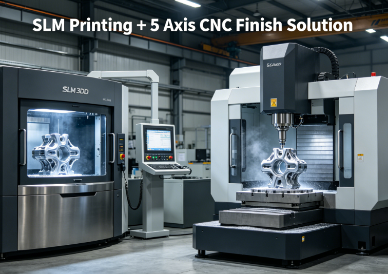
5: Support Removal & Precision Finishing Hybrid Machining
Lattice struts leave fragile residual support tabs after printing; rough grinding tears thin cellular structures. Zorapid’s hybrid finishing workflow:
- CNC wire EDM base plate cutting for clean part separation
- Micro abrasive flow machining (AFM): Flush internal lattice cavities to clear trapped powder impossible to reach by hand blasting
- 5-axis CNC milling on mounting flanges, bolt holes and mating surfaces to hit ±0.008 mm tight aerospace tolerances
- Media blasting for uniform surface finish Ra 1.6 μm (or mirror polishing Ra 0.4 μm for heat transfer lattices)
Step 6: NDT Aerospace Quality Validation (Full Compliance Audit)
Every lattice component ships with complete test reports matching EU EASA / US FAA standards:
- CT scanning: Full internal lattice inspection to verify strut thickness consistency, zero hidden cracks
- Tensile & compression coupon testing from the same build plate
- Surface roughness coordinate measurement (CMM) on all critical interfaces
- Material spectroscopy to confirm alloy purity
Core Advantages of Zorapid 3D Printed Aerospace Lattice Processing
We lay out hard, client-verified metrics instead of vague marketing lines—perfect for Google SEO high-conversion buyer intent.
- Mass reduction 30–65% per component A satellite bracket redesigned with gradient lattice cut weight 58%, lowering annual launch fuel expenses by over $12,000 per unit for our US aerospace client.
- Part consolidation cuts assembly failure points A 12-piece rocket engine cooling manifold merged into one single lattice-integrated printed part; eliminated 11 fastener joints and reduced assembly labor by 75%.
- Multi-functional single-part performance TPMS lattice manifolds boost heat dissipation by 28% vs solid machined equivalents, extending engine service life. Lattice inserts absorb 35% more vibration on UAV landing gear.
- 90% less raw material waste CNC machining buy-to-fly ratio hits 12:1; SLM lattice printing hits 1.5:1, slashing expensive titanium powder waste.
- Flexible low-to-medium batch production No custom casting molds required. Iterate 3–5 lattice design prototypes in 5 business days, vs 6–8 weeks for traditional casting tooling.
Most Common Lattice Processing Defects & Zorapid’s Fix Solutions
Aerospace engineers waste thousands testing flawed lattice prints from generic AM shops. Here’s the full defect troubleshooting guide we share with all partners:
| Defect | Root Processing Cause | Zorapid Targeted Fix Tech |
|---|---|---|
| Thin strut micro-cracks | Fast print cooling, uneven laser power | Controlled slow cool ramp + gradient power scanning |
| Trapped powder inside closed lattice | Large blind cellular cavities | Post-print micro AFM internal flushing + vacuum ultrasonic cleaning |
| Solid-lattice boundary warpage | Abrupt density shift without fillets | DFM auto-generate smooth transition radii pre-print |
| Low fatigue strength struts | Unclosed micro-pores from skipped HIP | Mandatory HIP treatment for all flight-grade parts |
| Strut thickness inconsistency | Poor powder flow, inconsistent layer melting | Pre-blended new/recycled powder + layer height calibration per build |
Real Zorapid Aerospace Lattice Case Study
Client Challenge: Low-orbit satellite support frame. Traditional solid Ti-6Al-4V machined part too heavy; multi-piece assembly prone to vibration loosening in space vacuum.
Our Lattice Processing Solution:
- Redesigned frame with variable density BCC gradient lattice via FEA load simulation
- SLM printed 0.4 mm uniform struts, full HIP densification
- 5-axis CNC finish mounting holes, CT full internal lattice inspection Final Measurable Results:
- 52% weight cut vs original solid machined component
- Single monolithic part, zero assembly fasteners
- Passed 10,000-cycle space vibration fatigue testing
- Lead time compressed from 7 weeks (CNC multi-piece) to 12 business days Client Feedback (US Aerospace Engineer): “Zorapid’s lattice process eliminated our biggest satellite mass penalty without sacrificing structural safety—their NDT reporting meets NASA audit requirements on first submission.”
Aerospace Application Fields for 3D Printed Lattice Parts
We split use cases by aircraft/space hardware so readers quickly match their project:
- Aircraft Structural Hardware Wing stiffeners, landing gear impact inserts, fuselage lightweight support brackets, UAV airframe internal frames
- Jet & Rocket Engine Thermal Components Conformal TPMS lattice cooling manifolds, fuel injector cellular heat sinks, turbine shroud lightweight inserts
- Satellite & Space Launch Hardware Orbit satellite support frames, rocket stage lightweight housings, vibration-damping payload brackets
- Aerospace Hydraulic & Pneumatic Systems Lattice cooling valve manifolds, low-mass fluid distribution blocks with internal cellular flow channels
Why Aerospace OEMs Pick Zorapid for Lattice 3D Printing Processing
Most overseas AM factories only offer printing; we deliver full vertical lattice manufacturing under one roof for global aerospace buyers:
- 20+ years aerospace additive manufacturing experience, AS9100 certified facility (3,000 m² precision workshop)
- In-house full workflow team: DFM lattice design engineers, SLM printing operators, HIP heat treatment lab, NDT CT scanning lab, 5-axis hybrid CNC finishing
- Exclusive gradient lattice DFM optimization process—hard to replicate by generic metal 3D printing suppliers
- Full English technical documentation, audit-ready test reports compliant with EASA, FAA and NASA standards
- Global shipping to US, EU, UK aerospace facilities with fast DHL air freight, 10–15 day door-to-door delivery
- Batch scalability: From single prototype lattice samples to 500-unit small-batch flight hardware production
FAQ
Can lattice 3D printed aerospace parts pass official flight certification?
Yes. All Zorapid lattice flight hardware undergoes HIP densification, full CT NDT and mechanical coupon testing. We provide complete material traceability and test packs for EASA/FAA audit submissions—our lattice satellite frames are already deployed on active low-orbit US satellites.
What’s the minimum strut thickness you can reliably print for aerospace lattices?
Stable production at 0.25 mm struts for Ti-6Al-4V and AlSi10Mg, with controlled laser parameter tuning and fine 20 μm print layers. We don’t recommend below 0.25 mm for load-bearing flight components due to fatigue risk.
Is SLM the only viable 3D printing tech for aerospace lattice parts?
EBM works for large low-detail lattices, but SLM delivers finer strut resolution and tighter dimensional tolerance for mission-critical thin cellular structures—90% of our aerospace lattice orders run on SLM systems.
How much cost saving can I expect switching from CNC solid parts to lattice AM?
It varies by part size and material. Titanium lattice components typically cut total landed cost 25–40% once you factor reduced material waste, eliminated assembly labor and lower long-term aircraft fuel/launch expenses. We provide free DFM lattice cost comparison reports for your CAD files.
Conclusion
3D printed lattice processing isn’t just a trendy lightweight trick—it’s a mandatory manufacturing upgrade for modern aerospace hardware chasing lower mass, better thermal performance and simpler supply chains. But successful lattice production hinges on specialized DFM design, tightly controlled SLM printing, mandatory HIP heat treatment and full NDT validation—steps most generic 3D printing shops cut to rush orders.
If you’re an aerospace engineer or procurement lead with a lightweight component project needing lattice optimization, send your CAD STEP files to Zorapid today. Our aerospace lattice engineering team will deliver a free DFM review, weight-reduction simulation data and transparent lead-time quotation within 24 working hours.