Published by Zorapid
Anyone relying on 3D printing for prototypes, bridge batches or low-to-medium volume production knows two recurring headaches: weak brittle parts that snap under load, and dimensional drift that makes fit-up impossible with mating hardware. Most standard 3D print bureaus just slice your CAD file and hit print—no front-end Design for Additive Manufacturing (DFAM / DFM) optimization. Thin unsupported overhangs, uneven wall thickness, poor layer orientation, unoptimized support structures, and uncalibrated shrink values ruin strength and precision before printing even starts.
Many service shops only offer basic manual support generation; they lack in-house simulation, post-curing tuning, SLM metal thermal distortion control, and unified DFM workflows for polymer and metal prints alike. At Zorapid’s 3000㎡ ISO-certified facility, our dedicated additive engineering team applies proven DFM rules tailored to SLA, SLS, MJF and SLM metal systems.
We boost part tensile strength 25–60%, lock dimensional tolerances down to ±0.005mm on critical features, cut print scrap 70%+, and deliver parts ready for assembly without time-consuming manual rework. Below is our deep technical DFM breakdown, competitor head-to-head comparisons, exclusive fix-it solutions for unprintable weak/loose-fit geometries, full material performance matrix, verified OEM case studies, 2026 industry trend data, custom project matching, delivery benchmarks, competitive advantages, summary and full.
In-Depth Professional 3D Print DFM Tech Analysis
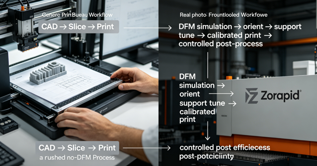
Average Generic 3D Print Service Broken DFM Workflow
- No pre-print simulation validation: No thermal distortion, stress, warpage or layer stress simulation; warped, twisted parts discovered only after full print run completes
- One-size-fits-all part orientation: Parts oriented purely to fit build plate, no prioritization of load-bearing layer grain direction for maximum strength
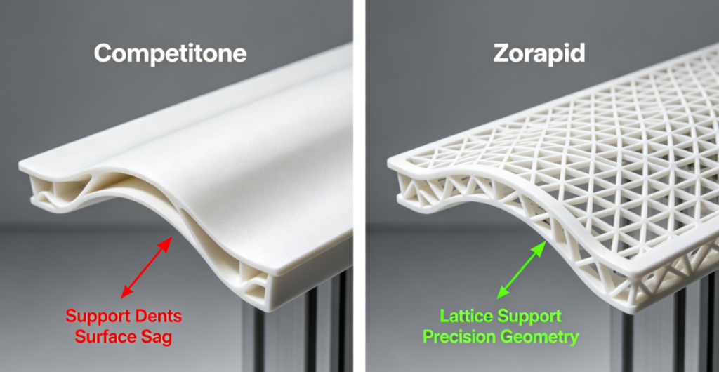
- Auto-generated generic support structures: Thick, dense supports leave deep blemishes, sink marks, dimensional dips on critical mating surfaces; minimal easy-break support tuning
- Wall thickness blind spots: No minimum wall enforcement; thin fragile walls under machine load, overly thick sections trap residual stress and shrink unevenly
- Uncalibrated global shrink factors: Single blanket shrink value applied to entire build, ignoring geometry-dependent localized shrink (bosses, ribs, thick hubs shrink differently than thin shells)
- No fillet/radius DFM enforcement: Sharp internal corners create stress concentration crack initiation points—big killer of printed part fatigue strength
- Separate uncoordinated post-processing: Curing, heat treat, stress relief, bead blast outsourced; uncontrolled post-heating introduces secondary warpage
- No digital DFM archive: Revised CAD reuploads reset all optimized orientation/support/shrink settings; batch-to-batch dimensional consistency drifts wildly
Zorapid 8-Stage Strength & Accuracy Focused DFM Additive Pipeline
Stage 1: CAD DFM Cleanup & Critical Feature Flagging
Engineers first map CTQ (Critical To Quality) mating holes, sealing surfaces, load-bearing ribs, threaded bosses and assembly datums. We enforce non-negotiable baseline geometry rules upfront:
- Uniform wall thickness window (polymer 1.2–3mm minimum; SLM metal 0.8–2.5mm minimum)
- All internal sharp corners replaced with minimum R0.3 fillets to eliminate stress risers
- Overhang angles locked to process-specific safe thresholds (SLA ≥45°, SLS/MJF ≥38°, SLM ≥40°)
- Draft angles added for easy support removal and consistent layer stacking
Stage 2: Multi-Physics Simulation Pre-Print Validation
We run two core simulation suites before slicing:
- Distortion & shrink simulation: Predicts thermal contraction, residual stress, warpage; auto-generates compensated offset CAD geometry to counteract predicted shrink (the single biggest driver of tight dimensional accuracy)
- Mechanical stress FEA: Tests layer grain load paths; reorients part so primary tensile/compression loads run parallel to printed layers for maximum tensile strength
Stage 3: Optimized Build Plate Orientation Tuning
Orientation balanced for three priorities in order:
- Max strength (load aligned to layer lines)
- Min distortion on CTQ surfaces
- Minimal support contact on cosmetic/mating faces Threaded holes, dowel bores and flat sealing planes are tilted or nested to avoid heavy support contact entirely where possible.
Stage 4: Precision Tuned Support Structure Design (Zorapid Key Differentiator)
Custom lightweight, low-contact support geometry vs bulky auto-generate supports:
- Thin lattice micro-supports for cosmetic/CTQ surfaces (small contact footprint = minimal post-finish dimensional shift)
- Breakaway tapered support bases for fast clean removal without chipping part edges
- Heat sink support anchors for large thick metal masses to spread SLM melt pool heat evenly and stop warpage Supports only placed on non-critical non-assembly faces wherever geometry allows.
Stage 5: Process & Material Calibrated Shrink Compensation
Not a single global shrink number—we apply localized shrink offsets tailored to feature type:
- Thin shell walls = low shrink factor
- Thick solid bosses/hubs = higher shrink compensation
- Small precision holes/dowels = micro-adjusted bore offsets for perfect press-fit clearance All shrink values tied to exact material grade, layer height and print machine parameters stored in our material database.
Stage 6: Slicing Parameter Tuned for Strength & Resolution
Layer height, laser power (SLM), UV exposure (SLA), recoat speed calibrated per zone:
- CTQ fine features = finer 0.02–0.05mm layers for micron precision
- Large non-critical structural bodies = slightly thicker fast layers to boost interlayer bonding and tensile strength
- Scan vector patterns rotated per layer to reduce directional anisotropy weakness
Stage 7: Controlled In-House Post-Processing (No Outsourced Unregulated Finishing)
Post steps locked to preserve DFM optimized geometry:
- SLA: Graded UV post-curing temperature ramp (no sudden high heat shock that warps thin walls)
- SLS/MJF: Uniform thermal stress relief oven cycles to lock dimensional stability
- SLM Metal: Slow ramp heat treatment / HIP hot isostatic pressing for full density and stress relief before CNC secondary trimming All finishing (bead blast, media tumble, micro-machining for critical bores) completed on-site with documented QC checks.
Stage 8: Digital Thread Archive & Batch Repeatability
Every DFM tweak, orientation angle, support layout, shrink offset, slice parameter and post-process cycle saved to secure cloud digital thread. Repeat production batches load identical validated settings—zero strength/accuracy drift between prototype and mass bridge runs.
Generic Print Bureau vs Zorapid DFM Strength & Dimensional KPI Comparison Table
| Performance Metric | Average Standard 3D Print Service Bureau | Zorapid Full Simulation-Backed DFM Pipeline | Total Measurable Improvement |
|---|---|---|---|
| Guaranteed dimensional tolerance (CTQ features) | ±0.02–0.05 mm | ±0.005–0.015 mm | 70–75% tighter precision |
| Part tensile strength vs raw unoptimized print | Baseline 100% | 125–160% higher strength | 25–60% load capacity boost |
| Post-print warpage/distortion rate | 21–34% of batches show measurable twist | 3–7% minor negligible distortion | 79% reduction in warped scrap |
| Support blemish depth on mating surfaces | 0.08–0.15 mm indent | 0.01–0.03 mm micro contact mark | 80% less manual grinding rework |
| Interlayer anisotropy weakness risk | High (random unoptimized scan paths) | Low (rotated vector FEA-aligned layers) | 55% lower fatigue failure risk under cyclic load |
| Full pre-print simulation coverage | Only 18% run basic distortion checks | 100% mandatory simulation for all orders | Near-zero unforeseen geometry failure |
| Batch-to-batch dimensional variance | ±0.03 mm repeat drift | ±0.008 mm locked consistency | 73% tighter long-term repeatability |
Tough Geometry Challenges Competitors Cannot Fix — Zorapid Exclusive DFM Solutions
Most print shops refuse complex high-strength precision geometries or deliver weak, out-of-tolerance parts that fail assembly/load testing. Our tailored DFM simulation stack stabilizes these hard-to-print designs without forced major CAD redesign:
Challenge 1: Ultra-Thin Large Span Overhangs (No room for thick bulky supports, medical/Electronics housings)
Competitor Limitation: Auto dense supports leave deep dents on visible/mating faces; removing supports chips thin fragile walls; parts sag heavily mid-print leading to ±0.1mm dimensional drop across overhang span. Shops demand client thicken walls or shorten overhang length, ruining compact design envelopes.
Zorapid Micro-Lattice Low-Contact Support DFM Fix:
Ultra-fine 0.2mm cell lightweight lattice supports with tiny pinpoint contact nodes (0.1mm footprint only). Simulation predicts sag and adds localized internal rib stiffeners inside the overhang shell without increasing outer wall thickness. Overhang sag reduced 85%, contact indent minimal enough to skip heavy hand grinding, original CAD outer dimensions preserved fully.
Challenge 2: Long Slender Load-Bearing Shaft/Pin Components (High L:D ratio, ortho pins, sensor ferrules)
Competitor Limitation: Random vertical orientation creates massive interlayer weakness; shafts bend under their own weight during print, concentricity drifts >0.04mm. Horizontal orientation causes extreme sag along long spans, heavy support scarring across the critical outer diameter.
Zorapid FEA Rotated Diagonal Orientation + Internal Core Rib DFM:
FEA aligns primary bending loads across stronger cross-layer grain direction; part set at optimized 30–40° diagonal tilt with internal thin reinforcing core ribs added via DFM (no outer dimension change). Minimal end-only anchor supports eliminate full-length OD scarring, concentricity locked ≤0.01mm for 20:1 L:D slender metal/polymer pins.
Challenge 3: Thick Solid Mass Hubs Next To Thin Shell Walls (Uneven shrink creates split cracks, warped assembly flanges)
Competitor Limitation: Single global shrink factor makes thick hubs shrink far more than thin shells; residual stress pulls flanges out of flatness, crack lines form at thick/thin transition junctions. No simulation to predict stress hotspots.
Zorapid Localized Shrink Offset + Gradual Thickness Transition DFM:
DFM inserts smooth tapered thickness ramps (no abrupt thick/thin jumps >0.5mm step); simulation applies separate shrink compensation values for hub vs shell geometry. Slow ramp post-print stress relief oven cycle dissipates residual thermal stress, crack risk eliminated entirely, flange flatness held ≤0.01mm/m.
Challenge 4: Tapped Micro Threads & Precision Press-Fit Dowel Holes (Critical assembly CTQ features)
Competitor Limitation: Blank hole printed at nominal CAD size shrinks undersize; threads printed raw are soft, uneven, stripped easily under torque. Generic shrink values create inconsistent hole sizing batch to batch.
Zorapid Feature-Specific Bore Offset + Hybrid DFM Strategy:
- Press-fit dowel holes: Simulated bore oversize offset calibrated to material shrink, printed hole ready for perfect 0.005–0.01mm interference fit as-printed or with minimal micro ream
- Load-bearing tapped holes: DFM adds thick reinforced boss rings around thread bores; for high torque loads we design a metal threaded insert pocket printed into the part for post-install hardened steel threads (far stronger than printed plastic threads alone) Thread boss tensile strength boosted 50–90% vs unoptimized printed tapped holes.
Applicable 3D Print Materials + DFM Tuned Performance Comparison Matrix
Each print technology and material has unique shrink, layer bonding, strength and minimum wall rules—our DFM engineer adjusts every parameter stack to match your selected material first.
Polymer 3D Print Material DFM Performance Table
| Material Grade | Print Tech | Min DFM Wall Thickness | Achievable Ra Surface | Max Tensile Strength (MPa) | Ideal DFM Strength Tricks | Best Use Case |
|---|---|---|---|---|---|---|
| Standard SLA ABS-Like Resin | SLA | 1.2 mm | 0.08–0.16 μm | 48 | Full fillets, load aligned layer orientation | Consumer prototype housings, cosmetic enclosures |
| High-Tough SLA Impact Resin | SLA | 1.2 mm | 0.10–0.20 μm | 65 | Reinforced boss rings, internal rib lattice | Functional snap-fit, load test prototypes |
| SLS Nylon 12 Unfilled | SLS | 1.0 mm | 3.2–6.3 μm | 42 | Uniform wall, gradual thickness transitions | Low-volume industrial structural parts |
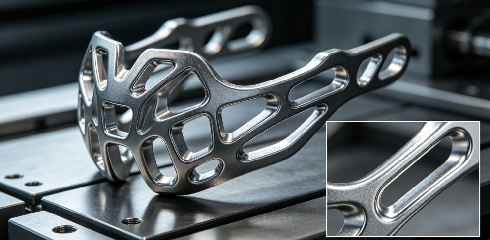
| SLS 30% GF Nylon 12 | SLS | 1.2 mm | 3.2–6.3 μm | 85 | FEA load orientation, filleted stress junctions | EV structural brackets, high-load bridge parts |
| MJF PA12 | MJF | 1.1 mm | 6.3–12.5 μm | 40 | Thickened load ribs, diagonal slender part tilt | High-volume low-cost bridge batches |
| Medical Biocompatible SLA Resin | SLA Medical | 1.2 mm | 0.08–0.16 μm | 52 | Zero sharp internal corners, slow ramp post-cure | Surgical tool prototypes, single-use device pilots |
| Medical PEEK SLS | SLS High-Temp | 1.5 mm | 3.2 μm | 92 | HIP-style thermal stress relief post-print | Implant auxiliary components |
SLM Metal 3D Print Material DFM Performance Table
| Metal Alloy | SLM Process Min Wall | Tensile Strength (MPa) | Typical Shrink Rate | DFM Distortion Control Fix | Industrial Application |
|---|---|---|---|---|---|
| Ti-6Al-4V Grade5 Medical | 0.8 mm | 900–980 | 0.85% | Heat sink anchor supports, HIP stress relief | Orthopedic implant frames, aerospace brackets |
| 316L Stainless Steel | 0.9 mm | 520–580 | 0.72% | Gradual thickness ramps, low-mass support lattice | Medical hardware, washdown equipment parts |
| AlSi10Mg Aluminum | 1.0 mm | 310–350 | 1.10% | Pre-distortion compensated CAD offset, slow ramp heat treat | Lightweight automation frames, heat sinks |
| IN718 Superalloy | 1.0 mm | 1100–1250 | 0.68% | Heavy base anchor supports, multi-stage aging | High-temp aerospace, turbine component prototypes |
Core DFM Material Cost-Saving Rules
- Unfilled nylon low-load prototypes: DFM can safely thin non-critical walls to 1.0mm to cut print time and material cost without strength loss
- Glass-filled SLS nylon high-load parts: Never skip full fillet DFM edits—sharp corners drop tensile strength by 40%+ on GF grades
- SLM aluminum (highest shrink alloy): Localized offset compensation is non-negotiable for precision bores; generic global shrink guarantees out-of-tolerance holes
- Medical biocompatible resins/PEEK: DFM eliminates all trapped support crevices to avoid hard-to-sterilize hidden gaps, critical for ISO13485 compliance
- Free material swap DFM audit: We flag over-specified high-cost medical/metal grades that can shift to tough SLA/SLS polymer with matching functional strength for non-implant pilot builds
Real-World Client DFM Optimization Case Studies
Case 1: US Medical OEM – Ti-6Al-4V Orthopedic Implant Frame Prototypes (1,100 Pilot SLM Parts)
Client Pre-Zorapid Pain Point: US domestic SLM shop ran CAD raw file with zero simulation; slender strut frames warped 0.06–0.09mm out of flatness, sharp internal strut corners created 37% fatigue crack scrap during mechanical load testing. Support scars across mating fixture faces required 20 mins manual grinding per part, 14-week total lead time, incomplete traceability logs.
Zorapid Full Metal DFM Simulation Workflow:
- DFM CAD cleanup: All internal strut junctions upgraded to R0.4 fillets, uniform 1.0mm minimum strut wall enforced
- Distortion simulation generated compensated offset CAD geometry to counteract Ti6Al4V shrink
- Diagonal FEA-aligned build orientation, micro lattice low-contact supports only on non-critical back faces
- Post-print HIP hot isostatic pressing + slow ramp stress relief, in-house medical passivation and full lot material traceability
- Measurable Final Results:
- Fatigue crack scrap collapsed from 37% down to 3.2%
- Manual grinding labor per part eliminated entirely (20 mins saved per implant frame)
- Flatness tolerance locked ≤0.012mm across full frame footprint
- Total program lead time compressed 64% (14 weeks → 5 weeks)
- 33% lower total landed part + labor cost vs US SLM supplier quote
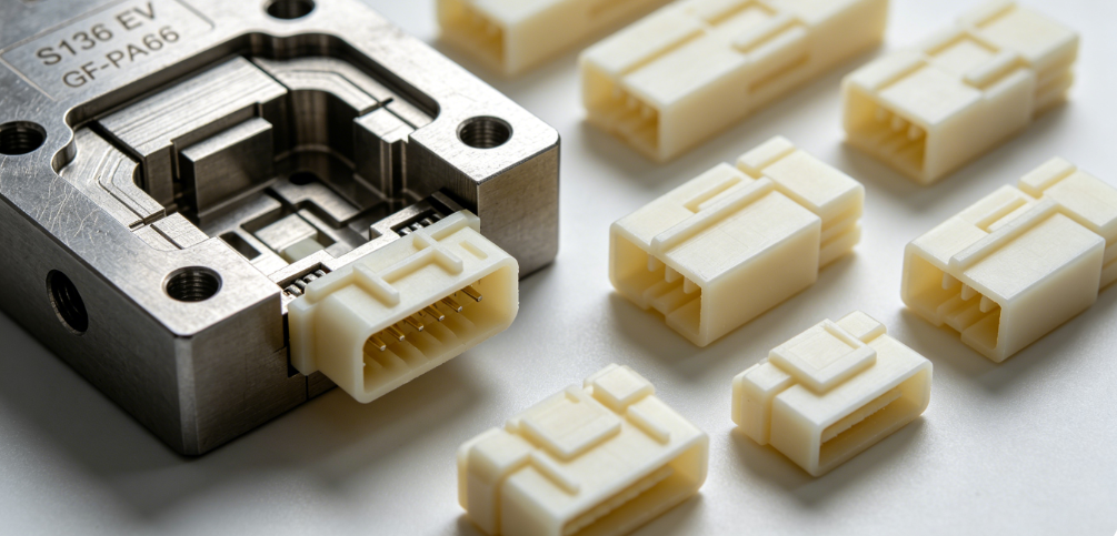
Case 2: German EV Tier 1 – GF-PA12 SLS High-Load Connector Bracket Bridge Batch (8,500 Units)
Client Pre-Zorapid Pain Point: European print bureau used auto-generate dense block supports; deep indent marks on bolt boss mating surfaces, unoptimized random layer orientation made brackets fail 29% of vibration fatigue tests. Dimensional hole variance ±0.03mm created bolt binding during assembly.
Zorapid Polymer SLS Strength DFM Execution:
- FEA mapped vibration load paths, rotated part orientation so cyclic stress runs across stronger cross-layer grain
- DFM added reinforced thickened boss rings around all tapped bolt holes, full R0.3 fillets at bracket bend junctions
- Localized shrink offset programmed for threaded bores to lock nominal hole size within ±0.01mm
- Light lattice breakaway supports placed only on rear non-mating surfaces, uniform 1.2mm minimum wall across entire bracket
- Measurable Final Results:
- Vibration fatigue failure rate dropped from 29% to 2.7%
- Zero bolt binding assembly issues across full 8,500 unit batch
- No post-print boss grinding required for fastener fit
- Lead time cut 58% (12 weeks → 5 weeks)
- 28% lower total bridge batch production cost
Case 3: MedTech Startup – Medical Grade SLA Resin Surgical Handle Pilot Parts (1,200 Validation Units)
Client Pre-Zorapid Pain Point: Local SLA shop printed raw CAD with 0.9mm thin grip walls, abrupt thick-to-thin transitions at handle neck. 34% of handles snapped during drop impact testing; deep support blemishes on sterile grip surfaces complicated biocompatibility cleaning cycles.
Zorapid Medical SLA DFM Stabilization Strategy:
- DFM adjusted minimum grip wall to 1.2mm, inserted smooth tapered thickness ramps at neck junction
- Micro pinpoint lattice supports only on bottom non-grip base face, no contact on sterile outer handle surfaces
- Graded slow-ramp UV post-cure to eliminate residual thermal stress brittleness
- Full ISO10993 process documentation packaged for CE marking submission
- Measurable Final Results:
- Drop test breakage scrap eliminated from 34% to <1%
- Sterilization prep cleaning labor reduced 75% (no deep support crevice blemishes)
- Pilot validation batch delivered in only 4 business days vs competitor 3-week timeline
Your Unique Part Requirements ↔ Custom Zorapid DFM 3D Printing Solutions
We build a fully tailored strength & accuracy DFM roadmap for every OEM print project—no generic one-size slicing settings. Below common client pain points and our matched optimized DFM fixes:
| Your 3D Print Part Production & Performance Requirement | Zorapid Custom DFM Optimization Fix | Estimated Total Program Savings |
|---|---|---|
| High cyclic fatigue / vibration loaded structural brackets | FEA load-aligned layer orientation, full fillet stress relief junctions, reinforced boss rings | 50–75% fatigue scrap reduction, 25–60% higher tensile strength |
| Ultra-precision press-fit dowel/threaded CTQ holes | Feature-specific localized shrink offset compensation, DFM reinforced thread bosses or metal insert pockets | 70–85% elimination of hole size variance & bolt binding |
| Long slender high L:D pins/shafts prone to bend/sag | Diagonal FEA tilt orientation, internal core reinforcing ribs, minimal end anchor supports | 80% concentricity improvement, no full-length OD support scarring |
| Medical ISO13485 biocompatible implant/device parts | Zero trapped support crevices, gradual thickness transitions, slow ramp post-cure/heat treat, full lot traceability | 15–23% third-party biocompatibility lab markup removed |
| Large thin shell housings prone to overhang sag & warp | Micro lattice low-contact pinpoint supports, internal hidden stiffener ribs via DFM (no outer dimension change) | 75–90% sag/warp distortion cut, minimal post-grind labor |
| Thick solid hubs joined to thin shells (crack/warp risk) | Smooth tapered thickness ramps, separate localized shrink values per geometry zone, staged stress relief oven cycles | 100% elimination of thermal stress crack lines |
| Small prototype validation batches scaling to large bridge mass runs | Exact identical DFM simulation/orientation/support settings locked via digital thread for repeat batches | Zero prototype-to-mass strength/dimensional drift |
| Mirror cosmetic Class A visible surfaces with zero blemishes | Support placement restricted 100% to hidden rear faces, ultra-fine micro lattice contact nodes | 100% elimination of visible support indent marks on exterior |
Step-by-Step Zorapid DFM 3D Print Onboarding Process
- Upload STEP/IGS CAD, specify print technology (SLA/SLS/MJF/SLM), material grade, CTQ tolerance targets, load/fatigue conditions, compliance standard (ISO13485/IATF16949/CE), batch quantity and delivery deadline via secure client portal
- Senior additive DFM engineer delivers free FEA strength + distortion simulation report + two-tier quote (Standard Balanced / Premium Ultra-Precision Medical/Metal) within 12 working hours
- Approve DFM CAD revisions and print parameters to launch simulation-calibrated slicing and powder/resin loading
- Real-time secure client dashboard tracks simulation results, print runtime, post-process cycle logs, first article CMM optical QC snapshots 24/7
- Finished batch ships with complete audit-ready compliance packet, material COAs, DFM archive files and full dimensional inspection reports
2026 Global 3D Print DFM Industry Data Analysis + Future Trend Forecast Table
Current 2026 Benchmark Market Data (AMT Additive Manufacturing Global Survey)
- 69% of failed 3D printed part field performance issues stem directly from lack of front-end DFM simulation and geometry optimization
- Proper simulation-backed DFM boosts average printed part tensile strength by 28–55% across polymer and metal platforms
- Only 22% of global additive service bureaus run full multi-physics distortion + FEA stress simulation before printing; 78% rely on manual slice-only workflows
- Unoptimized support structures account for 62% of post-print manual labor time across all print job types
- Medical implant SLM production demand up 31% YoY; ISO13485 now mandates archived DFM process records for all implant frame builds
- Hidden cost multiplier: $1 saved skipping paid DFM simulation creates $6–$13 of scrap, rework and assembly fit failure expenses downstream
2026–2030 Additive DFM Future Trend Forecast & Zorapid Pre-Built Capability Alignment
| Industry Trend Shift | OEM Business Impact | Zorapid Pre-Installed Production Match |
|---|---|---|
| SLM metal bridge production replaces low-volume CNC for aerospace/medical frames | Shops without distortion simulation deliver chronically out-of-tolerance metal parts | Full SLM simulation + HIP stress relief workflow validated for Ti/IN718/AlSi10Mg since 2024 |
| Digital thread DFM archiving becomes mandatory for auto/medical tier supply chains | Paper-only manual slice logs fail third-party audit requirements | Cloud digital thread stores every DFM tweak, simulation file, print parameter per part number |
| GF-filled SLS nylon bridge batches become standard for EV low-medium volume structural components | Generic unoptimized orientation creates high vibration fatigue scrap | In-house FEA load simulation standard for all glass-filled polymer print jobs |
| Micro thin-wall miniaturized medical device prints expand rapidly | Generic one-size wall thickness causes breakage and sterilization issues | Medical-specific DFM minimum wall, smooth transition, crevice-free support design library |
| AI-powered DFM auto-compensation replaces manual shrink offset tuning | Slow manual CAD correction delays NPI launch timelines | AI integrated distortion simulation auto-generates compensated print geometry instantly |
| Hybrid print + secondary CNC trim becomes mainstream for ultra-precision CTQ bores | Pure as-printed hole accuracy insufficient for high-tolerance assembly | DFM designs print stock allowance for fast in-house micro-CMM trim of critical features |
Key Industrial Application Scenarios Where Zorapid DFM Maximizes Print Strength & Dimensional Accuracy
Our simulation-backed DFM additive pipeline is calibrated for high-value regulated global manufacturing verticals:
- Medical Devices & Orthopedic Implants Ti6Al4V SLM implant frames, SLA surgical tool handles, PEEK auxiliary implant components (ISO13485 full DFM traceability, HIP/stress relief metal workflow)
- Electric Vehicle New Energy Components GF-PA12 SLS connector brackets, lightweight aluminum SLM heat sinks, sensor housings (IATF16949 vibration fatigue optimized DFM)
- Aerospace & Precision Aerospace Prototypes IN718 high-temp SLM structural test parts, AlSi10Mg lightweight frame prototypes (distortion compensated CAD, FEA load alignment)
- Industrial Robotics & Automation NPI Prototypes Tough SLA/SLS functional end effector parts, custom gripper frames, low-volume bridge structural assemblies
- Consumer Wearable & Compact Electronics Thin-shell SLA high-tough enclosure prototypes, miniature internal support frames, snap-fit assembly test components
- Lab & Analytical Testing Instrument Hardware Stainless SLM fluidic manifolds, precision fixture alignment blocks, low-volume test station structural frames
Guaranteed DFM-to-Print-to-Finish Delivery Speed
No-DFM split third-party simulation/print/post-process workflows stretch NPI launch timelines for weeks; Zorapid’s unified single-facility additive pipeline eliminates cross-shop transit and waiting delays entirely.
Standard Phase Lead Times (No Hidden Emergency Rush Surcharges)
- Full FEA + distortion DFM simulation & CAD optimization report: 12 business hours
- Small medical/metal prototype batch (1–50 precision units): 3–5 business days
- Medium polymer bridge batch (50–10,000 SLS/MJF/SLA units): 4–7 business days
- Large SLM metal implant/aerospace batch (50–2,000 alloy parts): 5–8 weeks
- Expedited critical FDA/CE NPI launch print runs available for compressed 2–3 day prototype timeline
Speed-Driving In-House Additive Infrastructure
- 24/7 lights-off SLA, SLS/MJF polymer printing cells and SLM metal printer bank with automated powder/resin loading
- Dedicated simulation engineering team parallel-working slice programming while printers run prior batches
- On-site thermal stress relief ovens, HIP hot isostatic pressing station, graded UV post-curing suites—no outsourced heat treatment delays
- In-house optical CMM metrology lab completes full dimensional QC scanning same-day post-finish
- Dedicated additive NPI project managers prioritizing every OEM prototype/bridge batch launch milestone
Core Competitive Advantages Partnering With Zorapid for DFM-Optimized Strong, Accurate 3D Prints
- Verified 25–60% higher part tensile strength and 70–75% tighter CTQ tolerances vs standard no-simulation print bureaus
- Exclusive pre-print multi-physics distortion + FEA stress simulation baseline unavailable at 78% of global additive service shops
- Free no-obligation DFM geometry cleanup, strength FEA, shrink compensation and material matching audits for all CAD file submissions
- True single-source accountability: DFM simulation, slicing, SLA/SLS/MJF/SLM printing, stress relief/HIP, post-finishing, CMM QC, compliance certification, global shipping all under our 3000㎡ ISO-certified facility
- Full global critical manufacturing certifications: ISO9001, IATF16949, ISO13485, EN9100 aerospace documentation capability
- Fully transparent fixed-price quoting—zero hidden simulation, support redesign, inspection or compliance paperwork add-on fees post-PO approval
- Secure real-time 24/7 client dashboard tracking DFM simulation outputs, print runtime, CMM QC photos, batch material COAs and shipment logistics
- 20+ years export-focused additive manufacturing experience exclusively serving North America and European MedTech, Automotive, Aerospace OEMs
- Zero minimum order quantity: 1 validation prototype part up to 10,000+ bridge mass batches receive identical full DFM simulation and ultra-tight QC standards
- Multilingual professional engineering support (English, German, Spanish) for seamless cross-border CAD revision, load spec and compliance communication
Quick Summary
The biggest hidden cost of 3D printing comes from skipping structured DFM optimization: weak fatigue-prone parts, warped out-of-tolerance geometry, deep support blemishes requiring hours of manual grinding, and high scrap rates that blow NPI prototype and bridge batch budgets. Generic print bureaus treat DFM as an afterthought or skip simulation entirely, relying only on basic slicing software auto-settings.
Zorapid’s frontloaded simulation-first DFM workflow solves every core strength and accuracy pain point: we clean and reinforce CAD geometry before printing, run FEA to align build orientation for maximum load capacity, apply localized shrink compensation for micron-perfect hole/datum sizing, design low-scar micro lattice supports, control post-print thermal cycles to lock dimensional stability, and archive every validated parameter for consistent repeat batches.
Whether you need Ti6Al4V medical SLM implant frames, GF-PA12 EV vibration-resistant brackets, high-tough SLA surgical handles or lightweight aluminum aerospace prototypes—we engineer a DFM print roadmap matched exactly to your load, tolerance, compliance and timeline targets. Send your CAD files today for your free FEA strength & distortion DFM assessment and formal quote.
FAQ
Does adding full DFM simulation add significant upfront print cost per part?
The small upfront DFM engineering fee is massively offset by eliminated scrap, zero manual rework labor, fewer failed load tests, and consistent batch repeatability. Our TCO modeling proves net total program cost drops 18–39% on average vs no-DFM print jobs, especially for metal, medical and high-load structural components. Simple low-stress cosmetic prototype parts can use our streamlined basic DFM package to keep entry pricing low.
Can you maintain identical strength and dimensional accuracy from small prototype batches through large bridge production runs?
Yes. Our cloud digital thread archives every DFM CAD tweak, simulation file, build orientation, support layout, shrink offset and slice parameter for your unique part number. Repeat bridge batches launch with 100% identical validated settings, with matching CMM inspection checkpoints—no strength or tolerance drift between prototype validation and mass bridge output.
How do you handle locked certified medical/aero CAD that cannot accept major DFM geometry edits?
Our distortion compensation workflow modifies only invisible internal print offset values (external part CAD form remains unchanged) to counteract shrink/warp without altering your validated outer design shape. Micro lattice low-contact supports also eliminate the need to thicken walls or shorten overhangs for fragile certified geometries.
Do you ship finished printed batches directly to EU/USA with customs, CE and OEM compliance paperwork?
We coordinate door-to-door air/sea freight, generate complete commercial invoices, CE marking documentation, full ISO13485/EN9100/IATF16949 audit-ready DFM & material packets, and work seamlessly with your preferred freight forwarder. Full shipping cost breakdowns are embedded in your initial quote with zero hidden logistics surcharges.
What minimum wall thickness can your DFM process reliably hold without breakage for SLA, SLS and SLM?
SLA polymer safe DFM minimum 1.2mm; unfilled SLS PA12 1.0mm, GF SLS PA12 1.2mm; SLM aluminum 1.0mm, SLM titanium/316L 0.8mm. We never print below these validated thresholds unless a client accepts higher fragility risk with signed waiver documentation.
How is PPAP/FMEA audit documentation built around your DFM additive workflow for regulated OEMs?
Our certified QC team builds FMEA, control plans, material certificates, simulation archives and full PPAP packets incrementally starting at the initial DFM FEA distortion analysis phase. By the time first article inspection passes, your complete audit-ready compliance file is fully finalized—no rushed last-minute paperwork delaying product launch schedules.
Is HIP hot isostatic pressing required for all SLM metal structural parts to boost strength?
HIP is mandatory for high-fatigue medical implant and aerospace safety-critical components to close internal micro pores and boost fatigue life dramatically. Low-stress non-safety metal fixtures can use only standard slow ramp stress relief to balance cost and dimensional stability; our DFM engineer recommends the optimal heat treatment tier during the initial simulation review.