Published by Zorapid Precision Sheet Metal Fabrication
If you run a sheet metal shop building electronic enclosures, EV brackets, medical housings, or light equipment frames, thin plate welding is your daily headache.
You’re working 0.5 mm–1.5 mm carbon steel, stainless, or aluminum panels. One tiny misstep with heat, fit-up, or technique creates two costly defects: burn-through holes and massive warpage that turns flat panels into warped potato chips.
You crank down weld power, slow your travel speed, grind out burn holes, re-fixture warped parts, and waste hours of rework—all because thin plate has almost zero thermal mass to absorb excess arc heat.
At Zorapid, our 3,000㎡ fabrication workshop handles thousands of thin-gauge sheet metal jobs for North American and European OEMs every year. We’ve refined repeatable thin plate welding standards that slash scrap rates by over 40% and cut post-weld straightening labor nearly in half.
Today we’re breaking down field-proven thin plate joint welding best practices—starting with DFM joint design, process selection, heat control tricks, defect fixes, and real production case data you can apply on your shop floor tomorrow.
The Core Challenge With Thin Plate Welding
Thin sheet metal (≤1.5 mm) has one fatal flaw for welding: it cannot hold heat evenly. When your arc hits the joint, energy concentrates instantly. Two non-negotiable failures follow:
- Burn-through: The puddle melts straight through the plate, leaving pinholes or full gaps that require grinding and patching.
- Thermal warpage: Uneven heating/cooling creates uneven shrinkage, bending panels out of flat tolerance, ruining cosmetic and dimensional specs.
Thick plate welding lets you run long continuous beads with high amperage. Thin plate welding is the opposite: every rule revolves around minimizing localized heat input. All our best practices tie back to this single core rule.
DFM Joint Design Best Practices for Thin Plate (Fix Defects Before Welding Starts)
Bad joint geometry is the root cause of thin sheet weld failures. Many OEMs send over CAD files with tight butt joints, zero flanges, and large gaps—guaranteed burn-through and warpage before your welder touches the torch.
We standardize four joint types for thin plate, ranked by production friendliness:
Lap Joint (Top Pick for Thin Gauge Production)
- Overlap 8–12 mm between two sheets; double thickness naturally absorbs extra heat
- For shear-load brackets, cabinet panels, and non-flush cosmetic surfaces
- Huge fit-up tolerance buffer: small gaps don’t immediately cause burn-through
- Best paired with stitch welds or spot laser welds to cut distortion
Flanged Corner Joint (Ideal for Enclosure Corners)
- Bend a small 5–8 mm flange on one panel to create a thicker weld land
- Eliminates thin edge melt-off common on sharp bare corners
- Far less warpage than raw corner butt joints for stainless steel housings
Grounded Butt Joint (For A-Surface Flush Cosmetic Parts)
- Only use if flush surface is mandatory; butt joints are the thinnest, highest-risk design
- Mandatory copper backing bar under the full seam to catch molten puddles
- Keep total fit-up gap ≤0.1 mm—any larger gap forces extra heat and burn holes
Offset Step Joint (For Sealed Thin Sheet Assemblies)
- Small formed step creates dual thickness at the weld line, seals liquid/gas enclosures
- Perfect for medical thin stainless cabinets and battery casings
Non-Negotiable Thin Plate Joint DFM Rules (Zorapid Standard Checklist)
- Eliminate gaps wider than 0.1 mm on all thin joints; gaps force excess filler and heat
- Avoid bare unflanged butt joints on material under 0.8 mm thick
- Space weld lines at minimum 10 mm away from bend lines to prevent secondary warping
- Design joint overlap/flange to add thermal mass where the arc will land
- Mark weld access clearance in CAD so torches/laser heads can reach full seam without obstruction
Choose The Right Welding Process For Thin Plates
Not all welding methods work for thin gauge. We match process based on material thickness, cosmetic requirements, and production volume:
| Welding Process | Best For Thin Plate Thickness | Key Thin-Plate Advantage | Shop Limitation |
|---|---|---|---|
| Pulsed TIG (GTAW) | 0.5–1.5 mm SS, Aluminum, Carbon Steel | Ultra-low heat input, clean cosmetic beads, easy heat control | Slower for high-volume batches |
| Pulsed MIG (GMAW) | 1.0–1.5 mm carbon steel | Fast cycle time, lower operator skill barrier | Higher distortion risk vs TIG/laser |
| Fiber Laser Welding | 0.4–2.0 mm all sheet alloys | Narrow HAZ, minimal warpage, automated repeatability | Higher upfront machine cost, tight fit-up required |
| Spot Resistance Weld | 0.6–1.2 mm lap joints | Zero filler, near-zero distortion | Limited to overlapping lap geometry only |
Quick shop rule from our weld team: For any thin A-surface stainless or aluminum parts, pulsed TIG or laser is non-negotiable. Standard non-pulsed MIG generates too much continuous heat for gauges below 1.2 mm.
7 Field-Proven Thin Plate Welding Execution Best Practices
These are the hands-on techniques our welders use every shift—simple, low-cost, zero extra equipment needed.
Practice: Prep Joints For Zero Contamination
Oil, rust, paint, and oxidation create porosity, unstable arcs, and weak fusion.
- Carbon steel: Wire brush + acetone wipe to bare metal 15 mm out from joint line
- Stainless steel: Stainless wire brush only (no cross-contamination from carbon steel tools)
- Thin aluminum: Degrease + scratch with dedicated aluminum brush to break tough oxide layer
- Critical: Clean both sides of the plate—hidden backside contaminants pop porosity mid-weld
Practice: Tight Fixturing + Copper Heat Sink Backing Bars (Biggest Warpage Fix)
Copper pulls heat away from the thin plate instantly, stopping burn-through and cutting warpage by up to 70%.
- Clamp panels rigid to a thick steel base plate with multiple clamps every 75 mm
- Clamp solid copper backing bar flush against the joint root for all butt and corner welds
- For large thin panels, add auxiliary aluminum chill bars along long seams to distribute heat
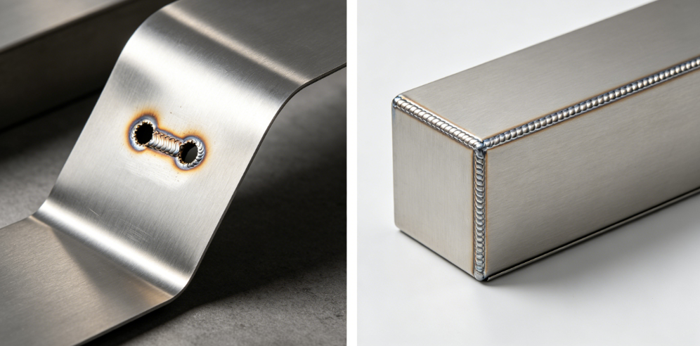
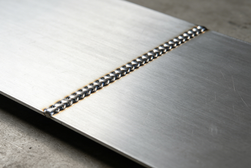
Practice: Stitch / Skip Welding Pattern (Never Run Full Continuous Beads)
A single long straight weld traps heat in one zone, bending panels permanently. Use staggered stitch welding:
- Lay small tack welds every 25–40 mm across the entire joint first (1-second tacks only)
- Weld a 15–25 mm short stitch on one end
- Jump to the opposite end for the next stitch
- Move to the middle segment, alternating hot zones to let metal cool fully between passes This staggered pattern eliminates cumulative heat buildup and shrinkage distortion.
Practice: Dial Down Heat + Use Tiny Filler Wire/Rods
- TIG: 0.8 mm or 1.0 mm filler rod only; amperage capped at 30–60A for 0.8–1.2 mm sheet
- MIG: 0.023” (0.6 mm) solid wire; low voltage 14–16V, push gun technique (10–15° angle) to reduce puddle heat
- Always start welding on scrap matching your plate thickness to dial in power before touching production parts
Practice: Pulse Mode Is Mandatory For All Thin Plate TIG/MIG
Pulse current alternates high-heat peak and low-heat background cycles. The plate gets brief cooling breaks mid-weld, preventing melt-through and wide heat-affected zones (HAZ).
For stainless thin sheet, pulse frequency 2–5 Hz delivers clean, tint-free weld beads without warping.
Practice: Optimize Shielding Gas Flow & Coverage
Poor gas coverage oxidizes thin weld roots, creates pinholes, and ruins cosmetic finish:
- Carbon steel MIG: 75% Argon / 25% CO₂ (C25 mix), flow 15–20 CFH
- Stainless / Aluminum TIG: 100% pure argon; add backside purge gas for flush butt joints to stop oxidation discoloration
- Avoid high gas flow rates—turbulence pulls air into the puddle and causes porosity
Practice: Control Weld Sequence & Interpass Cooling
Never weld adjacent sections back-to-back. Wait until the weld bead cools to dull red before stitching nearby.
For long cabinet seams, split the joint into four quadrants and weld in alternating quadrants to balance shrinkage forces evenly across the panel.
Zorapid Real-World Thin Plate Welding Case Study
A German medical OEM sent us 0.8 mm 304 stainless thin sheet enclosure drawings, with original shop issues:
- 38% scrap rate from burn-through on butt corner joints
- 2.2 mm average panel warpage post-weld, failing flatness tolerance
- 8 hours of post-weld grinding/straightening per batch
Zorapid Applied Thin Plate Welding Fixes
- DFM redesign: Swap bare butt corners for 6 mm flanged corner joints to add thermal mass
- Full copper backing bar fixture for all weld seams
- Pulsed TIG process with 0.8 mm stainless filler rod, staggered stitch weld sequence
- Full argon backside purge to eliminate heat tint on A-surfaces
Measurable Production Results After Implementation
- Scrap rate dropped from 38% to 1.2%
- Post-weld straightening labor cut by 82%
- Weld cosmetic quality passed medical class 1 surface inspection on first pass
- Total part lead time shortened 18% by eliminating rework cycles
Most Common Thin Plate Welding Mistakes Fabricators Repeat Daily
Avoid these costly errors that inflate scrap and labor costs:
- Running continuous full-length weld beads instead of stitch patterns (massive warpage root cause)
- Skipping copper backing bars on thin butt joints—invites burn-through
- Oversized gaps in joint fit-up, forcing extra heat and filler metal
- Using thick 0.035” MIG wire or large TIG rods for sub-1.2 mm sheet
- Neglecting surface cleaning, leading to porosity and weak joint fusion
- Welding close to bend lines, compounding thermal shrinkage distortion
- Ignoring backside shielding gas on stainless thin sheet, creating irreversible heat tint
- Insufficient clamping; panels shift mid-weld, creating uneven gaps and misalignment
Quick Defect Troubleshooting Cheat Sheet (Thin Plate Joints)
| Defect | Root Cause | Instant Thin-Plate Fix |
|---|---|---|
| Burn-through pinholes | Too high amperage, no copper backer, large joint gap | Lower power, add copper backing, rework fit-up to eliminate gaps |
| Severe panel warpage | Long continuous welds, unbalanced heat sequence, minimal clamping | Switch to stitch skip welding, add multiple clamps, chill bars |
| Weld surface porosity | Dirty base metal, unstable shielding gas, poor ground connection | Full solvent wire brush clean, calibrate gas flow, reposition ground clamp near joint |
| Stainless heat tint/discoloration | No backside argon purge, insufficient front gas coverage | Add root purge gas, increase torch gas coverage |
| Weak incomplete fusion | Travel speed too fast, insufficient filler, contaminated joint | Slow consistent travel, small filler rod, full pre-weld surface prep |
FAQ
What’s the best welding method for 0.6 mm thin stainless steel enclosures?
Pulsed TIG with copper backing bars is our standard production solution. For high-volume automated lines, fiber laser welding delivers even lower distortion and faster throughput. Avoid standard MIG for gauges under 0.8 mm.
Can I eliminate thin sheet warpage completely, or only reduce it?
Full elimination is impossible, but our standardized heat control, fixturing, and stitch welding methods cut warpage by 60–80% on most thin plate jobs, keeping parts within print flatness tolerances without heavy straightening work.
Do lap joints always outperform butt joints on thin sheet metal?
Yes for nearly all non-flush applications. Lap joints add double thickness thermal mass, tolerate minor fit-up gaps, and resist burn-through far better than thin butt geometry. Only use butt joints when a perfectly flush exterior surface is a hard design requirement.
How critical is copper backing for thin plate welds?
Non-negotiable for any sheet below 1.2 mm thick, especially butt joints. Copper absorbs excess arc heat instantly, stops puddle melt-through, and produces smoother, cleaner root welds with zero extra labor.
Final Wrap-Up
Thin plate sheet metal welding failure almost never comes from bad welders—it stems from poor joint design, unmanaged heat input, and skipped foundational prep steps.
By reworking your CAD joint geometry for thin-gauge manufacturability, selecting low-heat welding processes, using copper heat sinks, and switching to staggered stitch weld patterns, you wipe out burn-through and extreme warpage at the source. Scrap rates, rework labor, and delayed customer deliveries all drop drastically as a result.
At Zorapid, we integrate thin plate welding DFM reviews into every sheet metal quotation and NPI project. Our dedicated welding team optimizes joint design, fixturing, and process parameters before cutting any sheet material, so your parts pass inspection on the first production run.
If your workshop struggles with consistent thin sheet weld defects or high scrap costs, reach out to our engineering team for a free joint design and welding process audit today.