
Published:Zorapid.Ltd
Stainless steel (316L, 304, 17-4PH, 440C) has poor thermal conductivity, high ductility, and strong tendency to form BUE (built-up edge)—the #1 enemy of ultra-smooth Ra 0.2μm finishes. BUE smears, tears, and creates irregular surface texture; chatter, residual stress, thermal drift, and tool micro-wear also ruin fine finishes.
Ra 0.2μm = ultra-smooth precision sealing, medical, food, semiconductor, and fluid valve surfaces, requiring consistent micro-finish, no micro-tears, and controlled residual stress.
- Ra 0.2μm = average roughness 0.2 micrometers (mirror-like, no visible feed marks)
- Key principles: eliminate BUE, minimize chatter, reduce heat input, use sharp polished cutting edges, light consistent finish passes
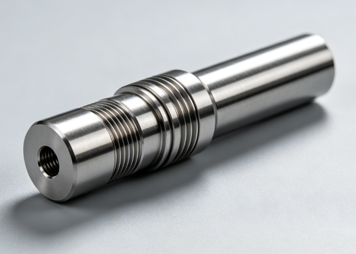
Stainless Steel Grades & Material Prep
Common Grades
- 316L / 304 Austenitic Stainless: Soft, ductile, most prone to BUE, common for medical/food/pharma fluid components
- 17-4PH / 15-5PH Precipitation Hardened: Higher strength, variable hardness (HRC 30–40), common aerospace/valve parts
- 440C Martensitic Stainless: Hardened (HRC 50+), wear-resistant valve seats, requires CBN fine turning
- 321, 316Ti: High-temperature austenitic grades, prone to work hardening
Material Preparations
- Use pre-stress-relieved bar / forgings: Reduce baseline residual stress, prevent post-machining dimensional drift and surface distortion
- Remove heavy roughing stock in staged passes before ultra-fine finishing
- Avoid cold-worked/hardened surface layers (work-hardened skin causes inconsistent finish)
- Validate bar straightness, remove surface scale/oxide, validate alloy via MTR/XRF
- Roughing baseline: Leave a uniform fine finish stock: 0.05–0.15mm (too much stock = excessive heat/chatter; too little = risk of tool rubbing)
- Do NOT deep rough on final finish passes
Machine & Fixturing Setup for Ultra-Fine Finishing
Machine Requirements
- High-Rigidity Precision Lathe / Mill-Turn: boxway construction, high-precision spindle (runout ≤0.002mm), linear glass scales, thermal compensation, temperature-controlled enclosure (±1°C ambient variation)
- Spindle: balanced high-precision HSK/BBT spindle, runout checked daily
- Enable spindle warm-up cycles (30+ mins) to eliminate thermal drift
- Avoid light general-purpose lathes (chatter = impossible Ra 0.2μm finish)
- Use spindle speed variation (SSV) function to break resonant chatter frequencies
- Software & Simulation: validated G-code, smooth blending of constant feed cycles, avoid sharp axis jerking
- Vibration Damping: anti-vibration machine bases, tuned mass dampers, eliminate loose belts/bearings
Fixturing & Workholding
- High-Precision Hydraulic Collets / Soft Jaws:
- Soft jaws pre-machined to match raw bar OD; minimize clamping distortion (thin-wall stainless is easily crushed)
- Do NOT clamp the final finished surface directly—clamp raw/datum zones only
- Dead centers, tailstock, or servo steady rests for slender shafts (L/D > 8) to eliminate deflection/chatter
- Balance workpieces for high-speed turning to avoid unbalanced vibration
- Minimize tool overhang as much as possible (critical for chatter suppression)
- Probing: on-machine probing cycles to validate datum alignment, compensate for thermal drift
- Cleanliness: fully clean fixturing, remove swarf/debris to prevent indentations/scratches
Tool Selection & Insert Geometry
Primary Tool Materials
- DLC / Mirror Polished Fine-Grain Carbide Inserts (Austenitic 316L/304) – #1 Choice
- Ultra-smooth mirror polished rake face, diamond-like carbon (DLC) coating to eliminate BUE adhesion
- Fine-grain substrate, sharp honed micro-edge (micro-chamfer 0.02mm, very light hone only—too heavy = poor finish)
- Positive rake geometry (+5° ~ +7°): reduces cutting force, minimizes material smearing
- Small nose radius: R0.2 mm / R0.4 mm (directly controls theoretical roughness formula:
Ra ≈ f²/(18×R) - Example: f=0.05 mm/rev, R=0.2 mm → Ra ≈ 0.007 μm theoretical baseline (real finish affected by BUE/chatter)
- 35°–45° high helix solid carbide for long reach boring
- PCD (Polycrystalline Diamond) Inserts: ultra-mirror finish, excellent BUE resistance for non-ferrous + soft stainless (austenitic), very sharp edges
- Not recommended for hardened martensitic stainless (440C)
- CBN (Cubic Boron Nitride) Inserts: for hardened stainless (440C, HRC >45), fine-grain honed CBN, light skim passes, avoid full flood coolant
- Edge honing critical to prevent chipping
- Tool Holders: shrink-fit / hydraulic rigid holders, anti-vibration damped boring bars for internal bores, minimal overhang
Key Insert Rules
- Sharp, correctly micro-honed edges (no burrs on cutting edge)
- Mirror polished rake face to stop BUE
- Positive rake geometry for austenitic stainless
- Replace inserts at first sign of micro-wear (check surface roughness regularly)
- Unpolished, negative rake, dull inserts (BUE guaranteed)
Optimized Cutting Parameters & Coolant Strategy
Theoretical Formula
Surface roughness is driven primarily by feed rate and nose radius, then BUE/chatter/heat.
Baseline Fine Turning Parameters (Austenitic 316L/304, DLC mirror carbide, R0.2 nose radius)
- Cutting Speed (vc): 120–180 m/min (constant surface speed G96)
- Feed Rate (f): 0.03–0.05 mm/rev (ultra-low fine feed)
- Depth of Cut (ap): 0.02–0.05 mm (light skim finish pass only)
- Spindle Speed Variation (SSV): enable to suppress chatter resonance
- Pass strategy: 1 single light mirror skim pass (new sharp insert only); avoid multiple repeated finish passes (risk BUE smearing)
Hardened Stainless (440C, HRC 50+, CBN)
- vc: 60–90 m/min, f:0.03–0.05 mm/rev, ap:0.02–0.04 mm, controlled mist lubrication (avoid full flood to prevent CBN thermal shock)
Coolant & Lubrication Strategy
- Austenitic Stainless (316L/304):
- High-pressure, filtered synthetic / semi-synthetic water-soluble coolant (low sulfur, corrosion-inhibited)
- Through-tool coolant delivery for direct cutting zone cooling + chip evacuation
- Maintain clean, filtered coolant (remove fine stainless swarf to prevent surface scratching)
- Avoid high-sulfur cutting oils (can cause surface staining, residual contamination in medical/food applications)
- Medical/semiconductor grades: use validated RoHS/biocompatible coolant formulations
- CBN Hard Turning (440C):
- Dry or minimal mist lubrication only (prevent CBN thermal shock and edge chipping)
- Chip Control: produce short, clean chips; prevent long chips from dragging across finished surfaces (add chip breaker geometry or peck cycles for bores)
Chatter & Residual Stress Control
Chatter Mitigation
- Minimize tool overhang, use anti-vibration boring bars for internal bores
- SSV spindle speed variation, avoid fixed resonant RPM
- Reduce radial cutting load (ultra-light ap, trochoidal/constant chip load cycles if applicable)
- Add sacrificial supports for thin-wall stainless; remove supports in final skim pass
- Validate modal resonance via FEA for slender shafts
Residual Stress Control
- Avoid aggressive deep passes that create tensile residual stress (causes dimensional drift + surface degradation)
- Staged roughing + validated low-temperature stress relief (if required by specs) before mirror finishing
- Limit heat input with light skim passes, controlled coolant
- Post-finish ambient soak validation (24hr) for precision medical/valve components
- Avoid hand polishing (creates uncontrolled residual stress and inconsistent Ra values)
In-Process Validation & Metrology
- Surface Roughness Measurement: Use contact profilometer (Ra filter: 0.8mm cutoff) to verify Ra ≤0.2μm at multiple positions (axial + circumferential)
- Validate after every tool change and batch start
- Do NOT rely solely on visual inspection (visible mirror ≠ true Ra 0.2μm)
- Dimensional Validation: Roundness tester, form measuring machine, CMM to check cylindricity, runout, taper
- Surface Integrity Check: Microscopy inspection for micro-tears, BUE smearing, work-hardened layers (critical medical/pharma parts)
- SPC Monitoring: Track Ra, cylindricity, runout across batches to catch gradual tool wear drift
Common Defects & Troubleshooting
1. Feed Marks / Higher Ra than Target
- Cause: too high feed rate, wrong nose radius, dull insert, axis jerk, chatter
- Fix: reduce feed rate, switch to R0.2 mirror DLC insert, SSV chatter suppression, validate spindle thermal compensation, new sharp insert
2. BUE Smearing / Dull Smeared Surface
- Cause: unpolished inserts, wrong rake angle, incorrect speed, poor coolant, work hardening
- Fix: mirror DLC positive rake inserts, optimize speed, clean filtered coolant, reduce dwell time, replace worn inserts frequently
3. Spiral Wavy Surface / Chatter Marks
- Cause: tool overhang, resonance RPM, unbalanced workpiece, loose spindle, thin-wall deflection
- Fix: shorten tool overhang, enable SSV, add steady rest/tailstock, re-balance spindle/part, check spindle bearings
4. Surface Discoloration / Heat Discoloration
- Cause: excessive cutting heat, insufficient cooling, slow speed, dwell marks
- Fix: constant speed, proper coolant, avoid dwell cycles, reduce ap, single light skim pass
5. Micro-Tears / Work-Hardened Layers
- Cause: dull inserts, excessive cutting force, cold-worked base material
- Fix: fresh sharp micro-honed mirror inserts, pre-stress-relieved blanks, light finish passes
Post-Treatment & Surface Integrity Preservation
- Deburring: controlled micro-brush/ultrasonic deburring only (no abrasive grinding/polishing)
- Avoid aggressive tumbling/polishing—ruins validated Ra 0.2μm surface
- Passivation (316L medical/food): RoHS compliant nitric/passivation per ASTM A967, validated no surface roughness degradation, mask critical mirror zones
- Electropolish (optional): only if formally validated to preserve Ra 0.2μm; perform after CNC mirror turning, not before
- Cleaning: ultrasonic DI water cleaning, dry fully to prevent stainless corrosion/staining
- Storage: corrosion inhibitor packaging, avoid direct contact with ferrous metals (galvanic corrosion risk)
- Coating: if PVD/DLC coating is required, apply validated thin coatings with masking; validate post-coat Ra
Quick Ra 0.2μm Stainless Turning Checklist
Pre-Setup
Pre-stress-relieved stainless bar validated, baseline roughing stock = 0.05–0.15mm
Precision lathe warm-up + spindle runout checked, thermal compensation enabled
Fixturing validated (no clamping on finish zones), steady rest/tailstock configured for slender parts
Mirror DLC/PCD/CBN micro-honed insert (R0.2mm nose radius), positive rake validated
Filtered biocompatible/corrosion-inhibited coolant system validated
Mirror Finish Turning Pass
Single light skim pass (ap=0.02–0.05mm, f=0.03–0.05 mm/rev) with new sharp insert
Constant surface speed (G96), SSV spindle variation enabled to suppress chatter
Through-tool coolant (austenitic stainless) / mist only (CBN hardened stainless)
No dwell cycles, smooth constant feed G-code blending
First part profilometer Ra validation (cutoff 0.8mm filter)
Inspection & Preservation
Full Ra validation at multiple axial/circumferential locations, confirm Ra ≤0.2μm
Roundness/cylindricity validation, check for BUE smearing/micro-tears
Controlled passivation/cleaning only, avoid abrasive post-polishing
SPC ongoing Ra monitoring, scheduled validated insert change cycles
Corrosion protection packaging, validated biocompatibility if medical/pharma
FAQ
What nose radius is best for Ra 0.2μm stainless steel turning?
R0.2 mm fine mirror inserts, paired with ultra-low feed (0.03–0.05 mm/rev). Larger nose radii help but increase chatter risk on thin-wall/slender parts. Always validate with profilometer.
Can I achieve Ra 0.2μm with standard uncoated carbide inserts?
Very difficult long-term—uncoated inserts rapidly develop BUE. Mirror DLC coated carbide inserts are the most consistent choice for austenitic stainless steel.
Can post polishing be used to achieve Ra 0.2μm?
Avoid manual polishing—it creates inconsistent roughness, residual stress, and risk of out-of-tolerance geometry. Achieve Ra 0.2μm directly via CNC turning to maintain GD&T precision.
Why does 316L stainless keep getting BUE and rough surface?
Austenitic stainless has high ductility and poor thermal conductivity. Fix with mirror DLC positive rake inserts, low feed, controlled coolant, SSV chatter suppression, frequent validated insert changes, avoid slow dwell RPM.
How to achieve Ra 0.2μm on internal stainless bores?
Use damped anti-vibration mirror DLC boring bars, minimal overhang, same ultra-light ap/f parameters, SSV chatter control, and profilometer bore roughness validation.
Is dry turning acceptable for Ra 0.2μm 316L?
Generally no—dry turning causes excessive heat, BUE, work hardening, and inconsistent roughness. Use filtered through-tool coolant for austenitic stainless mirror finishing.


