
Published:Zorapid.Ltd
Core Purpose & Aerospace Composite Tooling Basics
What is a Carbon Fiber Aero Layup Mold
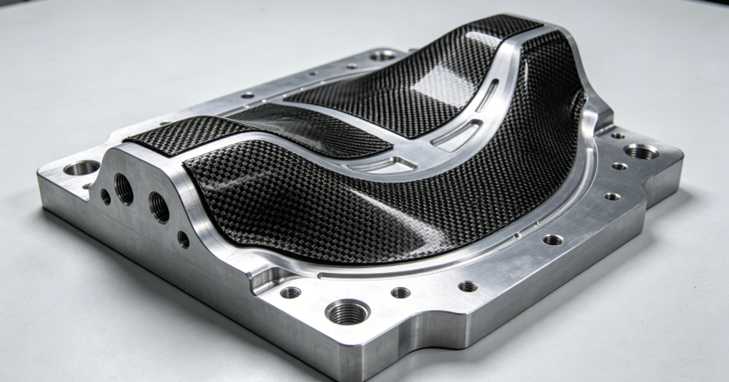
These are autoclave prepreg layup tools for aerospace CFRP primary/secondary structures (wing skins, fuselage panels, control surfaces, radomes, rotor components). They define the final composite geometry, cure shape, surface quality, dimensional accuracy, and ensure repeatable vacuum bag/autoclave curing (typically 180°C, 0.6–0.7 MPa pressure).
- Core requirement: thermal expansion (CTE) matching, rigid structural stability, ultra-smooth mold surface, precise 3D aerodynamic geometry, long autoclave cycle durability
- 5-Axis Value: Single-setup full freeform 3D contour machining, normal tool alignment to curved surfaces, consistent finish, reduced re-fixture error, integrated trim/scribe lines, and complex jigs/ports in one setup
- Governing Standards: AS9100, NADCAP, OEM specs (BMS, AIMS), ASTM D5528, ISO/ASTM composite tooling standards, FAA/EASA airworthiness requirements
- Key Risk: CTE mismatch distortion, surface defects causing composite porosity/telegraphing, residual tool stress, autoclave thermal warpage, composite delamination from poor mold surface quality
Mold Classifications
- Master Patterns / Plug Tools: Reference geometry, used for secondary mold fabrication (tooling board, foam, epoxy composite)
- Production Autoclave Tools: Reusable direct layup molds (Invar, carbon composite tooling, high-temp epoxy tooling, aluminum)
- Long-cycle aero production: Invar, BMI/cyanate ester carbon composite tooling
- Prototyping/short runs: high-density polyurethane tooling board, epoxy composite tooling
- Medium runs: high-temperature aluminum molds (with thermal coating/gel coat)
Key Mold Base Materials & CTE Matching Strategy
Invar (Fe-Ni Low Expansion Alloy)
- Spec: 36% nickel iron alloy, ultra-low CTE (near zero over autoclave cure temp range)
- Use Case: Primary flight critical composite tools, large wing skins, precision aerostructures, tight GD&T aerodynamic surfaces
- Machining Notes: Tough, gummy, prone to BUE; sharp coated carbide/PCD tools, light finish passes, controlled coolant; 5-axis full contour finish
- Pros: Excellent CTE match with carbon prepreg, minimal autoclave thermal distortion, long cycle life
- Cons: High cost, heavy, slow machining, long lead time
Carbon Fiber High-Temp Composite Tooling (BMI / Cyanate Ester Matrix)
- Spec: Carbon fabric reinforced BMI/bismaleimide or cyanate ester resin (Tg ≥200°C), CTE engineered to match CFRP prepreg
- Use Case: Medium-large autoclave tools, low mass, matched CTE, high-cycle aero production
- Machining Notes: Similar to general CFRP—risk of delamination, fraying, dust erosion; PCD compression spiral 5-axis tooling, dry/MQL cold air cutting, full dust extraction
- Pros: Lightweight, matched CTE, autoclave capable >180°C, low thermal distortion
- Cons: Tool base residual stress, anisotropic geometry drift, surface gel coat maintenance cycles
High-Density Epoxy Tooling Board / Polyurethane Tooling Board
- Spec: Dense rigid epoxy/PU blocks (low/medium temp: ~120–150°C)
- Use Case: Prototyping, development tools, non-primary structural layup molds, master plugs
- Machining Notes: High-speed 5-axis router, avoid excessive heat (softens resin), dry cold air cutting, prevent surface melting
- Pros: Fast 5-axis machining, low cost, easy revisions
- Cons: Limited autoclave temperature, short cycle life, high CTE mismatch, prone to thermal drift
High-Temp Aluminum (6061 / 7075)
- Spec: Anodized / hard coat / high-temp gel coat coated aluminum
- Use Case: Moderate temperature, smaller composite parts, secondary structures
- Machining Notes: Standard 5-axis aluminum parameters, mirror finish, thermal compensation, apply high-temp gel coat release system
- Pros: Fast machining, rigid, moderate cost
- Cons: High CTE mismatch with CFRP, significant thermal distortion over large spans (requires thermal modeling/compensation)
Core CTE DFM Rule
- Use FEA thermal simulation to calculate autoclave cure distortion; apply 5-axis pre-compensation offsets to the mold CAD geometry to correct CTE mismatch shape shift
- Specify unified primary datum outside the cure surface for repeatable inspection and fixturing
5-Axis Machine Specs & Fixturing
5-Axis Machine Requirements
- Large-format Gantry 5-Axis / Heavy-Duty Trunnion 5-Axis:
- Rigid boxway frame, high-damping structure, linear glass scales, volumetric error compensation, thermal control (±1°C ambient), RTCP validated kinematics
- High-speed balanced spindle (15k–30k RPM), HSK tooling, spindle runout <0.003mm
- Full digital twin simulation (Vericut/NX/HyperMILL), validated machine-specific 5-axis post-processor
- Dedicated ULPA carbon dust extraction, conductive grounding, ESD protection (for composite dust)
- Laser volumetric calibration, periodic rotary axis kinematic validation
- Large aero molds: gantry 5-axis (Zimmermann, etc.) with long travel for full wing/spar contours
- Controller: Fanuc / Siemens / Heidenhain with RTCP, smooth multi-axis blending, look-ahead jerk control
Fixturing & Workholding
- Unified primary datum frame, zero-point pallet systems, vacuum spoilboard / full-area vacuum fixturing for large curved surfaces
- Sacrificial backing plates to eliminate vibration and edge chipping; avoid direct clamping on final mold layup surfaces
- Fiducial alignment features, CMM datum targets, permanent tool alignment holes (non-layup zones only)
- Steady rests / support gantries for large thin composite mold shells to reduce 5-axis finish chatter
- Probe cycles for automated WCS datum alignment, periodic thermal drift correction
- Validation: Full 5-axis dry run simulation, collision checking, slow 10% feedrate validation before finish passes
- Ambient Control: Temperature controlled machine enclosure to minimize long contour thermal drift during multi-hour 5-axis finishing
5-Axis CAM Toolpath & DFM Guidelines
CAM Software
NX CAM, HyperMILL, Mastercam, PowerMill – full 5-axis simultaneous / 3+2 indexed strategies.
- Roughing: 3+2 indexed 5-axis adaptive trochoidal roughing, constant chip load, reduce residual stress and chatter
- Semi-Finish: Rest-machining residual stock clearing, reduce air cutting, maintain consistent finish stock (0.1–0.3mm)
- Finish: Full simultaneous 5-axis flowline / UV / swarf milling, keep tool normal to mold surface (constant scallop height), minimize ball end tool scallop error
- Smooth 5-axis blending, reduce B/C axis jerk, avoid sharp direction reversals
- Variable spindle speed (SSV) to break resonant chatter modes on large thin mold shells
- Define scribe lines, ply reference marks, vacuum port features, edge trim geometry directly in 5-axis CAM
- Full collision simulation (machine + fixture + tool holder) to prevent gouging, especially deep mold cavities
- Create validated 5-axis CAM templates, formal ECO revision control (AS9100 change management)
DFM Rules
- Add blended radii (R≥3mm) to all sharp mold corners, eliminate micro-notches that telegraph to composite parts
- Define zone GD&T: critical aerodynamic layup surfaces (CTQ) vs structural backing zones
- Design vacuum channels, edge seals, and release film grooves before 5-axis machining; mask them during finish surface passes
- Add sacrificial datum lugs removed post-inspection; avoid thin unsupported mold skin geometry
- FEA thermal cure simulation to generate pre-distorted compensated mold geometry for 5-axis machining
- Specify layup ply boundary reference marks with controlled depth (no deep cuts into core mold structure)
- Avoid deep blind pockets that trap gel coat/resin; design cleanable geometry for mold maintenance cycles
Tooling & Cutting Parameters for Composite Tooling
Tool Selection
- Composite Tooling Boards / CFRP Composite Molds:
- PCD (polycrystalline diamond) compression spiral end mills, diamond-coated carbide, sharp micro-honed edges
- Anti-chatter variable pitch geometry, short rigid tool overhang, shrink-fit/hydraulic holders
- Avoid standard uncoated carbide (rapid wear, fraying, delamination)
- Key: Compression spiral geometry to balance top/bottom ply shear stress, prevent edge delamination
- Invar Metal Molds:
- Fine-grain coated carbide, TiAlN, controlled micro-hone; avoid excessive heat buildup and BUE
- Finishing: small nose radius ball/bullnose PCD/CBN inserts, light skim passes
- Aluminum Molds: DLC mirror finish carbide for final contour passes
- Coolant Strategy:
- Composite tooling boards / CFRP molds: filtered cold dry air / MQL only (avoid flood coolant, resin swelling/degradation)
- Invar/metal molds: filtered synthetic coolant, high-pressure through-spindle coolant as appropriate
- Continuous ULPA dust extraction for carbon composite mold machining, avoid carbon dust accumulation
Baseline Parameters (General Composite Tooling Board / Carbon Composite Mold 5-Axis Finish)
- vc: 400–600 m/min, fz: 0.05–0.08 mm/tooth, shallow ap (0.2–0.5mm per pass), climb milling
- Multiple light finish passes, single final mirror skim pass, avoid deep aggressive finishing
- Variable spindle speed variation (SSV) for large thin mold shells to reduce resonant chatter
- Validate feed/speed with coupon test cuts; define formal tool life schedules
Surface Finish, Tolerance & Autoclave Validation Specs
Dimensional Tolerance Specs
- CTQ Aerodynamic / Primary Layup Surfaces: ±0.05 mm (or tighter per OEM GD&T), validated CMM / laser scan inspection
- General Mold Backing Structure: ±0.1–0.2 mm
- Key Datum Features: ±0.02 mm repeatability
- CTE Compensated Tolerance: validated via thermal autoclave cycle testing, SPC Cpk ≥1.33 for CTQ features
- Reference: ASME Y14.5, ISO 2768, AS9102 FAI
Surface Finish Specs
- Primary Autoclave Layup Surface: Ra ≤0.4 μm (mirror/gel-coated finish), consistent contour scallop height (0.02–0.05mm max scallop)
- Prevent scallop marks telegraphing into composite skin surface (aerodynamic roughness risk)
- Post 5-axis finish: controlled polishing/gel coat application (mask datum/CTQ reference surfaces)
- Gel coat system: high-temperature aerospace tooling gel coat (autoclave compatible, semi-permanent release system)
- Validate surface roughness via profilometer (0.8mm cutoff ISO 4287)
- Visual Inspection: No 5-axis tool scallop marks, micro-chipping, resin damage, residual tool marks
- Large Mold Validation: Full laser 3D scanning, global contour deviation mapping, first article AS9102 FAI
Autoclave Validation
- Thermal cycle validation (autoclave cure profile), vacuum integrity testing (leak check), repeat contour measurement after full cure cycles
- Verify composite part surface quality (no telegraphing defects, porosity, surface waviness)
- Check vacuum bag seal geometry, edge trim geometry, ply reference alignment after autoclave cycles
Post-Processing & Release System Preparation
Post 5-Axis Finishing
- Controlled light polishing (not aggressive grinding) only for final layup surface, preserve core 5-axis contour geometry and datum features
- Mask CMM datum features, alignment holes, trim reference features
- Gel Coat Application: Apply aerospace high-temp tooling gel coat, cure per spec, re-light finish gel coat surface (validate Ra)
- Apply semi-permanent aerospace composite release agent (multi-layer, cured/buffed per OEM specs)
- Do NOT apply release agent directly to raw 5-axis machined composite/CFRP surfaces (risk resin adhesion, mold damage)
- Mold Structural Upgrades: Add backing ribs, heating/cooling lines, vacuum manifolds, autoclave frame mount features
- Mold Conditioning: Full thermal autoclave break-in cycles to stabilize residual stress, reduce long-term drift
- Mold Maintenance Schedule: Periodic re-gel coat, re-finish, CMM inspection, re-5-axis touch-up finish cycles
Compliance, Traceability & First Article Inspection
Quality & Regulatory Framework
- AS9100, NADCAP, IPC/aircraft OEM specs, full batch traceability (MTR mold material records, 5-axis process logs, CAM revision history, operator logs)
- First Article Inspection: AS9102 FAI, CMM full GD&T validation, laser scan contour mapping, autoclave process validation, PFMEA/control plans
- Change Control (ECO): Formal revision process for 5-axis CAM toolpaths, post-processors, fixturing, material changes
- Material Validation: Invar/CFRP tooling MTR, XRF alloy verification, CTE test reports, thermal cycle certification
- Documentation: 7+ year record retention per aerospace program requirements, serialized mold ID, periodic re-qualification audits
SPC Monitoring
- Track CTQ contour deviation, surface roughness, vacuum seal geometry across autoclave cycles
- Alert limits for mold surface degradation, CTE drift, contour warpage
Common Defects & Troubleshooting
- 5-Axis Scallop Marks / Surface Waviness (Telegraphing Risk)
- Root: Poor 5-axis finish toolpath, inconsistent scallop height, axis jerk, chatter, wrong ball nose tool stepover
- Fix: Full 5-axis flowline finishing, reduce stepover, smooth blending, SSV chatter suppression, validate RTCP, mirror skim pass
- Composite Mold Edge Delamination / Fraying
- Root: Incorrect tool geometry, reverse fiber cutting, insufficient backing support, excessive feed/speed, dull PCD tools
- Fix: PCD compression spiral tools, helical entry, sacrificial backing, reduce cross-fiber feed, validated climb milling
- Global Mold Thermal Distortion / CTE Mismatch Shape Shift
- Root: Uncompensated CTE difference, residual mold stress, autoclave thermal gradient
- Fix: FEA thermal simulation + 5-axis pre-distortion CAD compensation, matched CTE mold material, thermal break-in cycles, CMM post-cure validation
- Tool Residual Stress / Long-Term Mold Warpage
- Root: Aggressive 5-axis roughing, asymmetric stock removal, unrelieved composite tool base stress
- Fix: Staged roughing, intermediate stress relief cycles, symmetric 5-axis roughing strategy, 24hr ambient soak validation + CMM check
- Gel Coat Release Failure / Composite Sticking
- Root: Poor 5-axis surface finish, incomplete gel coat cure, incorrect release agent application, residual tool marks
- Fix: Re-validate 5-axis mirror finish, formal gel coat/release agent process, periodic mold re-gel coat maintenance
Safety & Dust Control
- Carbon Composite Dust: Full ULPA dust extraction, grounded machine/ductwork, anti-static hoses, ESD safety protocol
- PPE: respirators (P100/N95), safety goggles, anti-static gloves/clothing
- Carbon dust explosion risk assessment, inert gas suppression, regular machine/duct cleaning
- Daily filter validation, conductive floor/tool grounding, air quality monitoring
- Machine Safety: Full 5-axis simulation validation, slow dry runs, emergency stop validation, formal crash prevention protocols
- Lock validated post-processors/CAM templates, avoid ad-hoc manual G-code edits
- Regular spindle/axis calibration, volumetric error correction, rotary kinematic validation
- Waste Disposal: Segregated composite/invar waste, regulated composite waste handling
Quick Reference Checklist
Quick 5-Axis Aero Layup Mold Checklist
Define CTE matched mold material, FEA thermal distortion simulation + 5-axis CAD compensation
5-axis full digital twin simulation validated, RTCP/kinematics calibrated, correct machine-specific post-processor
Unified primary datum defined, vacuum/sacrificial fixturing validated, slow dry run complete
PCD/composite-specific 5-axis tooling, validated finish parameters, mirror finish Ra ≤0.4μm on layup surface
AS9102 FAI / full CMM/laser scan contour validation, SPC Cpk validation for CTQ aerodynamic surfaces
High-temp gel coat + semi-permanent release system applied (mask datums), autoclave thermal break-in cycles complete
Full vacuum integrity test, composite layup trial validation, no telegraphing surface defects
Carbon dust extraction/ESD safety validated, formal mold maintenance schedule created
AS9100 traceability logs, ECO change control, periodic re-qualification audit schedule
FAQ
Should I use Invar or carbon composite tooling for large aero primary layup molds?
Primary flight critical long-cycle production: Invar (ultra-low CTE, minimal autoclave distortion). Medium cycles + weight reduction: BMI/cyanate ester matched CTE carbon composite tooling (requires 5-axis finish and CTE validation). Prototyping: epoxy/PU tooling board.
How to prevent 5-axis scallop marks from telegraphing to CFRP aero parts?
Use full 5-axis flowline constant-scallop finishing, reduce ball nose stepover, validate Ra ≤0.4μm, apply uniform high-temp gel coat, and laser scan full contour deviation before autoclave use.
What is the biggest risk for 5-axis aero composite layup molds?
Autoclave CTE mismatch thermal distortion and residual mold stress drift, followed by surface finish telegraphing defects and composite delamination from mold edge damage.
Is full simultaneous 5-axis always required, or can 3+2 indexed 5-axis be used?
3+2 indexed 5-axis for large general mold backing structure; full simultaneous 5-axis only for critical freeform aerodynamic contour finishing to maintain uniform scallop height and surface finish.
How often should a production aero composite mold be re-finished via 5-axis?
Per OEM tool maintenance specs (typically periodic CMM inspection + re-gel coat; re-5-axis touch-up only if contour deviation/telegraphing defects develop, validated by FAI).
Can raw 5-axis machined composite mold surfaces be directly used for prepreg layup?
No—raw 5-axis composite surfaces have micro-defects, residual dust, and variable roughness; must apply validated high-temp tooling gel coat + semi-permanent release system after 5-axis finishing.
Closing Notes
5-axis aero composite layup mold machining is a precision contour + CTE matching + autoclave process validation workflow, not just pure surface finishing. The core goals are accurate aerodynamic contour geometry, matched thermal expansion, consistent ultra-smooth layup surfaces, and AS9100-compliant repeatability.
- Use 5-axis to achieve uniform freeform contour finish and single-datum accuracy
- Prioritize CTE matching and thermal validation over pure surface gloss
- Formal FAI/laser scan validation before autoclave production runs
- Establish structured mold maintenance cycles to prevent telegraphing defects and autoclave drift


