
Published:Zorapid.Ltd
Composite layup molds (tooling) produce carbon fiber prepreg structural panels (fuselage skins, wing skins, spars, ribs, UAV fuselage/wing panels) via autoclave or out-of-autoclave (OOA) vacuum bag curing (typical 180°C, 0.6–0.7 MPa pressure cycles).
- Primary risk: CTE (coefficient of thermal expansion) mismatch distortion, residual cure stress, surface telegraphing defects, vacuum leaks, and long-term autoclave cycle degradation
- Governing Standards: AS9100, NADCAP composites processes, OEM specs (BMS, AIMS), FAA/EASA, ISO14644 (if applicable), formal FAI/AS9102 validation
- Key Performance Goals
- CTE Matching: Match in-plane CTE to carbon fiber structural panels to minimize thermal cure distortion
- Dimensional Stability: Repeatable contour tolerance, minimal warpage over hundreds of autoclave cycles
- Surface Integrity: Smooth contour, no tool marks, prevent telegraphing defects, controlled surface roughness
- Vacuum Integrity: Full vacuum integrity, leak-tight edges, consistent pressure distribution across large panels
- Thermal Stability: Uniform temperature distribution, resist high-temperature autoclave cycling
- Traceability: Full material batch records, change control, formal validation (critical aircraft flight structures vs non-flight UAV structures)
- Distinction: Flight-critical aircraft tooling = high-spec low-CTE composite tooling / Invar hybrid tooling; UAV non-flight/short-run panels = epoxy tooling board / basic epoxy composite tooling
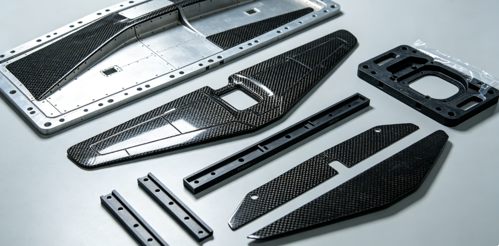
Tooling Material Selection & CTE Matching Strategy
Main Composite Tooling Material Families
- BMI (Bismaleimide) / Cyanate Ester Carbon Prepreg Tooling (Primary Aircraft Production Tooling)
- Spec: High Tg (≥200°C), quasi-isotropic carbon fiber layup, engineered low CTE (matched to carbon prepreg ~0–5×10⁻⁶/°C)
- Autoclave capable: 180°C+ repeated cycles, long life (hundreds of cycles), low thermal distortion
- Pros: Lightweight, CTE-tunable via ply orientation, low autoclave distortion vs aluminum, faster production vs full Invar
- Cons: Higher cost, residual anisotropic stress, requires formal cure cycles, periodic re-finish maintenance
- DFM: Quasi-isotropic layup ([0/±45/90]s) to balance directional CTE and reduce warpage; FEA thermal simulation to validate CTE response.
- Epoxy Composite Tooling (Mid-Run UAV / Development Aircraft Tooling)
- Spec: High-temp epoxy carbon/glass prepreg, Tg ~150–180°C
- Use: Medium-run UAV panels, prototype aircraft structures, OOA curing, shorter cycle life (dozens to ~100 cycles)
- Pros: Lower cost, easier layup, faster fabrication
- Cons: Higher CTE mismatch risk, limited high-temperature cycle life, higher long-term drift
- Epoxy/PU Tooling Board (Master Plugs / Short-Run UAV Prototypes)
- Spec: Dense machinable epoxy tooling board (e.g., SikaBlock, M974), room/moderate temp cure
- Use: CNC master plugs, one-off molds, rapid UAV prototype tooling, not long-term autoclave production
- Pros: Fast 5-axis CNC machining, easy revisions
- Cons: Poor high-temperature resistance, high CTE mismatch, limited autoclave cycles
- Hybrid Tooling (Invar Frame + Composite Surface Laminate)
- Spec: Invar backup frame + matched CTE composite surface skin
- Use: Large primary aircraft panels: combines ultra-low CTE Invar structural stability with lightweight composite layup surface
- Balances precision, thermal stability, weight and cost
- Other Materials (Limited Use)
- Aluminum: High CTE mismatch (~23×10⁻⁶/°C), only non-critical secondary UAV tooling, requires thermal compensation
- Additive Composite Tooling (3D carbon fiber/ULTEM): Rapid UAV prototype tooling, validate CTE and thermal cycles before autoclave production
CTE Validation Rules
- Perform FEA thermal cure simulation (autoclave ramp/soak/cool cycles) to predict distortion and apply CAD pre-compensation offsets
- Measure actual tool CTE via thermal cycle scanning; validate full autoclave thermal cycle contour drift
- Create formal tool layup specification (ply orientation, material, cure cycle) to lock CTE performance; formal ECO change control (AS9100)
- Distinguish surface laminate CTE from backup structure CTE; primary layup surface must have matched CTE
Master Pattern / Plug Fabrication
Master Plug (Reference Geometry) Workflow
- CAD validated nominal geometry (including FEA CTE pre-compensation offset), formal GD&T zone definition
- Base structure: epoxy tooling board, composite core, or aluminum substrate; 5-axis CNC rough + finish machining
- Finish: Ra ≤0.4μm mirror contour finish, validated via laser scanning/CMM
- Add datum fiducials, alignment holes, ply reference scribe lines, vacuum groove geometry
- Surface sealing & priming: high-temp tooling gel coat, fill pinholes, eliminate porosity, validate no surface defects
- Formal gel coat cure cycles, light polish, 10x magnified inspection for micro-pits
- Apply initial semi-permanent release system (validated aerospace grade, no silicone release agents)
- First Article Validation: Full laser 3D scan / CMM FAI (AS9102), confirm contour deviation tolerance (typically ±0.05mm or tighter for aircraft primary panels)
- UAV non-critical plugs: relaxed tolerance, but still validate contour before mold layup
- Clean & condition master plug: controlled environment (temperature ±1°C), prevent ambient drift; formal master tool control & periodic revalidation
Composite Mold Layup & Autoclave Cure Process
Composite Tool Laminate Layup Workflow
- Material Prep: Validated BMI/cyanate ester/epoxy tooling prepreg, controlled freezer storage, conform to out-life specs, MTR batch traceability
- Cut prepreg via automated ply cutter (ATL/AFP automated tape laying for large molds), follow validated quasi-isotropic ply schedule
- Include core/stringer backing structure for rigidity (honeycomb core, composite stiffeners)
- Integrate vacuum channels, edge seals, trim guides, ply alignment markers during layup (avoid cutting into primary layup surface)
- Layup & Vacuum Bagging
- Apply validated semi-permanent release system to master plug surface
- Lay up tool prepreg sequentially, debulk per specified cycle (vacuum debulking to eliminate voids)
- Add breather, bleeder, release film, vacuum bagging film; full vacuum leak check (target <0.5 psi/min leak rate)
- Thermocouple placement for autoclave thermal profiling, validate full mold temperature uniformity
- Autoclave Cure Cycle (Validated per Resin Spec)
- Ramp rate, dwell temperature, pressure, cool-down rate defined via DOE process validation
- Slow controlled cool-down to minimize residual cure stress (critical for BMI/cyanate ester composite molds)
- Full thermal mapping to verify no hotspots, uniform cure across large mold surface
- Post-cure (if specified by resin spec) to complete cross-linking, reduce residual volatiles and residual stress
- Demold & Initial Inspection
- Controlled demold to avoid surface damage, measure baseline contour via laser scan / CMM
- Check for voids, delamination, porosity via NDT (ultrasonic inspection for flight tooling per NADCAP)
- 24hr ambient soak dimensional validation to capture residual stress drift, record baseline SPC data
5-Axis CNC Finish Machining & DFM Rules
5-Axis Machining Process
- Fixturing: Unified primary datum system (non-layup structural zones), vacuum/frame fixturing, temperature-controlled environment
- RTCP validated 5-axis gantry machine, volumetric laser calibration, thermal compensation
- Full digital twin simulation (Vericut/NX), constant scallop height flowline 5-axis finish toolpaths, minimize scallop marks
- PCD/diamond-coated tooling, light skim finish passes, avoid aggressive cutting that introduces new residual stress
- Validate spindle runout, periodic kinematics calibration, avoid chatter on large thin mold skins
- DFM Key Rules
- Zone GD&T: define CTQ layup surface vs structural backing zones; apply tight tolerance only to primary layup surface
- Add blended radii (R≥3mm), eliminate sharp corners (stress risers, telegraphing risk)
- Locate parting lines/vacuum channels outside primary aerodynamic/layup surfaces
- Create sacrificial datum lugs (removed after FAI validation), avoid direct fixturing on layup surface
- Add thermal compensation geometry for autoclave cycles; separate conformal cooling/heating lines if applicable
- Scribe ply reference lines with controlled depth (no deep cuts into surface laminate)
- Surface Finish Spec
- Primary Aircraft Layup Surface: Ra ≤0.4μm (mirror finish), no visible 5-axis scallop marks, validated profilometer measurement
- UAV non-critical surfaces: controlled finish to prevent telegraphing defects, consistent texture
- Mask critical datums during gel coat/release coating processes
Mold Infrastructure: Backing Structure, Heating, Vacuum & Fixturing
Backing Structure Design
- Structural frame (composite stiffeners, Invar/aluminum frame) to reduce global deflection under autoclave pressure/vacuum
- Topology optimization FEA to balance rigidity and weight, minimize deflection under full autoclave load
- Add transport lifting points, alignment pins, autoclave mounting interfaces, ground reference datums
- Thermal barrier design to reduce temperature gradients across large molds (major warpage risk)
Vacuum System Design
- Integrated reusable vacuum ports, perimeter edge seal gaskets, continuous vacuum channels, redundant vacuum lines
- Full vacuum decay leak testing before each autoclave run, validated edge seal geometry
- Avoid deep hidden vacuum channels (resin trap risk), add cleanable geometry for maintenance
Thermal Control
- Embedded heating/cooling lines (conformal routing) for OOA curing or autoclave supplemental thermal control
- Thermal mapping validation, uniform temperature profile (±3°C across surface)
- Thermocouple monitoring, closed-loop thermal control for repeatable cure cycles
Alignment & Fixturing
- Permanent CMM reference datum blocks, laser alignment fiducials, repeatable jigs for automated ply layup (AFP/ATL)
- Anti-deflection supports for large thin mold shells, eliminate resonant vibration during 5-axis machining
- Dedicated autoclave tooling frames to reduce autoclave movement and shape shift
Surface Preparation, Release Systems & Gel Coat
Surface Preparation
- Post 5-axis finish: controlled polishing (non-aggressive), remove residual tool marks, validate surface roughness
- Avoid over-polishing (alters contour geometry); preserve validated CTE surface laminate
- Ultrasonic clean, remove residual machining coolant/debris, validate no contamination
- NDT inspection (ultrasonic scan) for hidden voids/delamination (flight-critical aircraft tooling)
- Gel Coat Application
- Apply validated aerospace high-temperature tooling gel coat (match autoclave temp range), full cure per manufacturer spec
- Light finish polish gel coat surface, re-validate Ra and contour deviation; mask datums
- Avoid gel coat buildup variation that changes CTE and contour geometry
- Release System Application
- Semi-permanent multi-layer aerospace release system (Chemlease etc.), no silicone-based release agents (contamination risk for composite prepreg)
- Follow validated cure/buff cycle for release agent; test first layup trial to confirm clean demolding, no adhesion
- Reapply/recondition per formal maintenance schedule; periodic extractable/residue validation (flight structures)
Validation, Metrology & Aerospace Compliance
Dimensional Validation
- First Article Inspection (FAI): AS9102, CMM / laser 3D scan full contour mapping, GD&T validation, SPC Cpk ≥1.33 for CTQ features
- Thermal cycle validation: multiple full autoclave cure cycles, re-scan contour drift, establish baseline drift limits
- 24hr ambient soak validation, long-term dimensional monitoring
- UAV non-flight tooling: simplified 3D scan validation, formal pilot panel cure validation
Material & Process Validation
- Full MTR traceability, XRF material verification, CTE testing, NDT composite inspection (NADCAP compliant for flight tooling)
- Formal PFMEA/DFMEA, process validation, autoclave cure cycle validation, residual stress validation
- Composite tool laminate mechanical testing (tensile, shear, fatigue cycling), autoclave cycle endurance testing
Regulatory & Quality Compliance
- AS9100 QMS, NADCAP composites accreditation (flight aircraft tooling), formal configuration control (ECO/ECN)
- Document retention (≥7 years for aerospace prime programs), full batch travelers, MES process logs
- Risk assessment per ISO 14971, formal supplier audits, periodic re-qualification audits
- Pilot panel validation: cure structural test panels, inspect porosity, NDT, mechanical testing, fit check validation
- UAV defense tooling: ITAR/export compliance validation if applicable
Common Defects & Troubleshooting
Global Thermal Warpage / CTE Mismatch Distortion
- Root: Incorrect ply layup / CTE mismatch, unvalidated autoclave cool-down cycles, residual bulk cure stress, thermal gradients
- Fix: FEA CTE simulation + CAD pre-compensation, quasi-isotropic layup, slow controlled autoclave cool-down, thermal barrier design, periodic laser scan validation, formal re-finish cycles
Surface Telegraphing / Scallop Marks / Micro-Texture Defects
- Root: Poor 5-axis toolpath, excessive stepover, chatter, inconsistent gel coat, underlying voids/delamination
- Fix: 5-axis constant-scallop flowline finishing, reduce stepover, validate RTCP, re-polish/gel coat, NDT check for subsurface defects, formal mold surface maintenance
Vacuum Leaks / Edge Seal Failure
- Root: Damaged edge geometry, degraded release/gel coat, worn gaskets, poor vacuum channel design, bagging variation
- Fix: Redesign perimeter vacuum seals, periodic edge re-finish/re-gel coat, pre-autoclave vacuum decay testing, replace gaskets
Tool Laminate Voids / Delamination
- Root: Inadequate debulking, poor autoclave pressure profile, out-of-spec prepreg, incorrect cure cycle
- Fix: Formal debulk cycles, DOE autoclave cure validation, NDT periodic inspection, rework via composite repair (per NADCAP), replace if excessive damage
Resin Adhesion / Demold Difficulty
- Root: Incomplete release system cure, contaminated surface, improper gel coat, silicone contamination
- Fix: Full release system validation, remove silicone contamination via validated cleaning process, reapply semi-permanent release per SOP, formal demold trials
Long-Term Surface Degradation (Autoclave Cycling)
- Root: High-temperature fatigue, repeated release agent stripping, thermal cycling fatigue, gel coat degradation
- Fix: Formal mold maintenance schedule, periodic re-gel coat/release conditioning, define maximum cycle life, track cycle count via MES
Mold Maintenance & Life Cycle Management
Formal Maintenance Plan
- Track total autoclave cycle count, establish validated maximum cycle life (BMI tooling: hundreds of cycles; epoxy UAV tooling: tens of cycles)
- Weekly: vacuum leak testing, visual inspection, surface wipe, release agent conditioning
- Monthly: laser contour scan, CMM check CTQ features, NDT spot check, gel coat/release reconditioning
- Annual: full 3D scan, formal re-finish (5-axis light skim), NDT full inspection, re-qualification autoclave cycle validation
- Formal composite repair procedures (NADCAP if flight tooling), documented repair history
Storage & Handling
- Controlled temperature/humidity mold storage, support jigs to prevent long-term sagging/distortion, FIFO cycle usage tracking
- Avoid direct sunlight, thermal cycling, uneven loading; use protective covers for layup surfaces
- Document end-of-life criteria (excessive contour drift, persistent leaks, subsurface delamination), formal retirement process
Change Control
- All mold geometry/process changes require formal ECO approval, re-FAI validation, re-autoclave cycle validation (AS9100), update PLM CAD data
- Create digital twin mold model for baseline comparison and future rework
Quick Checklist
Composite Aircraft/UAV Panel Mold Fabrication Checklist
CTE matched tool laminate design (quasi-isotropic BMI/cyanate ester), FEA thermal simulation + CAD pre-compensation
Master plug 5-axis finish + FAI CMM/laser validation, formal gel coat & release system validation
Composite tool prepreg MTR traceability, validated autoclave cure cycle, slow controlled cool-down, NDT inspection
5-axis constant-scallop finish layup surface, Ra ≤0.4μm, validated contour tolerance, zone GD&T defined
Full vacuum decay testing, redundant vacuum system, edge seal validation, autoclave thermal mapping
AS9100 / NADCAP validation (flight aircraft), formal PFMEA/control plans, full batch traceability logs
Multiple autoclave cycle thermal validation, 24hr soak dimensional validation, SPC Cpk monitoring
Pilot composite panel cure validation (NDT, porosity, structural/fit check)
Formal mold cycle tracking, scheduled maintenance/re-gel coat/release conditioning, re-qualification schedule
UAV non-flight tooling: define cycle limits, validate autoclave thermal performance, formal prototype panel validation
FAQ
What is the primary difference between aircraft flight tooling and UAV composite panel tooling?
Aircraft flight tooling requires CTE-matched BMI/cyanate ester composite tooling + AS9100/NADCAP validation, long-term autoclave cycle stability and formal structural validation. Most UAV non-flight tooling uses epoxy composite/epoxy tooling board for shorter runs, simplified validation and lower cost, and does not require full NADCAP accreditation.
Why is CTE matching more important than ultra-high absolute surface gloss?
CTE mismatch causes global panel shape distortion across autoclave temperature cycles, which directly affects aerodynamic geometry, assembly fit and structural performance. Gloss is cosmetic; CTE matching controls core dimensional repeatability.
Can composite tooling replace Invar molds for large aircraft primary structures?
Validated BMI/cyanate ester matched CTE composite tooling can achieve Invar-level dimensional repeatability for many large autoclave panels while reducing weight and cost, but critical ultra-tolerance primary aircraft structures may still use hybrid Invar/composite tooling for ultimate thermal stability.
How to prevent residual stress warpage in large composite molds?
Use quasi-isotropic layup, formal debulk cycles, slow controlled autoclave cool-down, FEA thermal pre-compensation, 24hr ambient soak validation, and avoid aggressive 5-axis roughing that introduces new residual stress.
Is silicone release agent acceptable for aerospace autoclave composite tooling?
No, silicone residues contaminate prepreg, cause bonding defects and prevent proper semi-permanent release function. Use validated non-silicone aerospace semi-permanent release systems only.
How often should a production aircraft composite autoclave mold be revalidated?
Per OEM prime specifications (typically annual formal 3D scan + NDT validation), plus periodic SPC monitoring of contour drift and vacuum integrity; formal re-qualification after major rework/ECO changes.
Closing Notes
Composite aircraft/UAV panel mold fabrication is a CTE engineering + autoclave process validation + dimensional repeatability program, not just surface machining.
- Flight-critical aircraft: BMI/cyanate ester matched CTE composite tooling, AS9100/NADCAP validation, formal thermal cycle validation, full traceability
- UAV non-flight panels: epoxy composite/tooling board tooling for cost/lead-time optimization with core vacuum/contour validation
- Always validate with pilot panel cure runs and formal 3D metrology before full serial autoclave production, and implement structured cycle-based maintenance


