
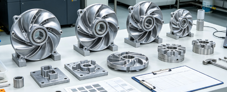
Published:Zorapid.Ltd
5-axis mold machining creates precision freeform autoclave layup molds for carbon fiber aircraft/UAV structural panels (wing skins, fuselage skins, spars, control surfaces, radomes). These molds define aerodynamic contour, dimensional stability, surface quality and vacuum integrity for prepreg CFRP autoclave curing (typically 180°C, 0.6–0.7 MPa pressure cycles).
- Core 5-axis value: single-setup full contour machining, normal tool axis alignment, constant scallop finish, minimal re-fixture error, integrated ply marks/vacuum features, and FEA CTE-compensated geometry
- Governing Standards: AS9100, NADCAP composites, OEM specs (BMS/AIMS), FAA/EASA, ASME Y14.5 GD&T, AS9102 FAI
- Primary risk: CTE mismatch thermal distortion, residual stress warpage, 5-axis scallop telegraphing defects, mold surface damage, vacuum seal geometry errors, long-term autoclave cycle degradation
- Key mold substrate types:
- Master plugs: epoxy/PU tooling board, aluminum, foam
- Composite tooling: BMI/cyanate ester carbon prepreg (long-run production)
- Hybrid tooling: Invar frame + matched CTE composite surface skin
- Invar low-expansion alloy (ultra-precision primary aircraft structures)
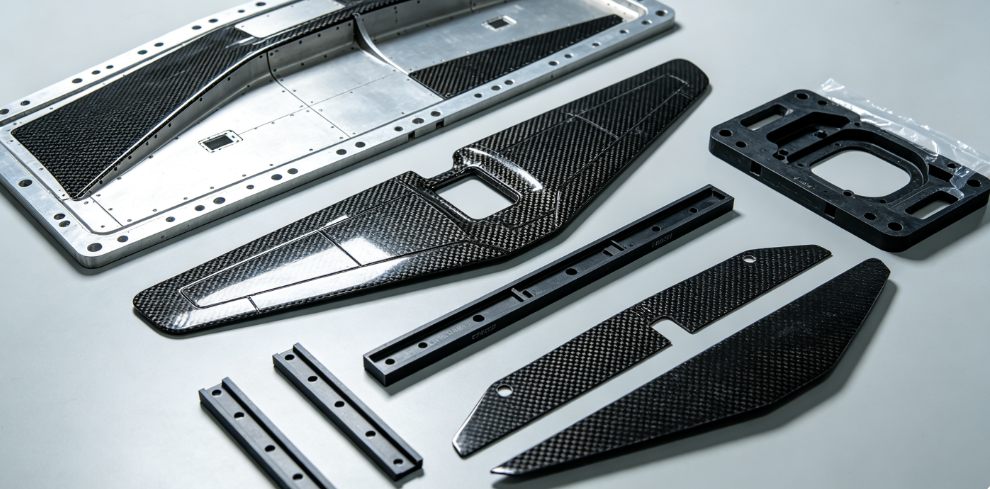
5-Axis Machine & Facility Requirements
Machine Type
- Large-format gantry 5-axis (long travel for full wing/fuselage panels) or heavy-duty trunnion 5-axis for smaller precision molds
- Rigid boxway frame, high-damping structure, linear glass scales, volumetric laser calibration, RTCP validated kinematics
- Balanced HSK high-speed spindle (15,000–30,000 RPM), spindle runout <0.003mm, thermal compensation
- Full digital twin simulation (Vericut/NX/HyperMILL), validated machine-specific 5-axis post-processor
- Ambient temperature control (±1°C), ESD grounding, ULPA dust extraction (composite mold machining), clean air enclosures as needed
- In-machine probing for automated datum alignment, periodic thermal drift correction
Environment & Safety
- Controlled temperature/humidity workshop to eliminate long contour thermal drift during multi-hour finishing passes
- Carbon dust control: full ULPA vacuum extraction, conductive hoses/grounding, anti-static PPE, explosion risk mitigation
- Formal dry-run collision validation before finish passes, locked validated CAM templates (AS9100 change control)
Fixturing & Datum Strategy
- Unified Primary Datum System
- Create permanent non-layup datum blocks/fiducials outside the primary aerodynamic surface (CMM reference, laser alignment, automated AFP ply layup)
- Add sacrificial datum lugs (removed after FAI validation), avoid direct clamping on critical layup contour surfaces
- Large molds: vacuum spoilboards, modular aluminum frame fixtures, anti-deflection support gantries to reduce chatter and deflection
- Use repeatable zero-point pallet systems for rework/re-finish cycles
- Key Rules
- Lock WCS coordinate system; avoid repeated manual re-probing
- Validate fixture deflection under 5-axis cutting loads
- Document datum locations in PLM CAD for future rework and inspection
- Add alignment features for automated tape laying (ATL/AFP) equipment
5-Axis CAM Toolpath & DFM Guidelines
CAM Software & Toolpath Strategies
- NX CAM, HyperMILL, Mastercam, PowerMill
- Roughing (3+2 indexed 5-axis): Adaptive trochoidal constant chip load roughing, reduce residual stress and chatter, leave consistent semi-finish stock (0.1–0.3mm)
- Semi-Finish: Rest-machining residual stock clearing, reduce air cutting, validate residual stock uniformity
- Finish (Full Simultaneous 5-Axis Flowline / UV / Swarf Milling): Keep tool normal to curved mold surface, fixed small scallop height (0.02–0.05mm max), smooth multi-axis blending, minimize B/C axis jerk and direction reversals
- Variable spindle speed (SSV/SSV) to break resonant chatter modes on thin composite mold shells
- Integrate controlled-depth ply reference scribe lines, vacuum channel geometry, trim guides directly in 5-axis CAM
- Full collision simulation (machine + fixture + tool holder), validate tool length/holder clearance
- Apply FEA thermal CTE pre-compensation geometry (critical for autoclave thermal distortion correction)
DFM Rules
- Zone GD&T: define CTQ aerodynamic layup surfaces vs structural backing zones; apply tight tolerance only to primary layup zones
- Add blended radii (R≥3mm), eliminate sharp corners (stress risers, telegraphing risk)
- Locate vacuum/perimeter seals, edge gaskets, trim geometry outside the primary aerodynamic contour
- Avoid deep blind pockets (resin trap risk); design cleanable vacuum channels
- Follow CTE-matched composite tool ply orientation (quasi-isotropic layup) to reduce anisotropic warpage
- Specify uniform finish stock, avoid aggressive deep cuts that introduce new residual stress
Tooling & Cutting Parameters
Tool Selection
- Epoxy/PU Tooling Board & Carbon Composite Tooling
- PCD (polycrystalline diamond) compression spiral end mills, diamond-coated carbide, variable pitch anti-chatter geometry
- Short rigid tool overhang, shrink-fit/hydraulic holders to minimize deflection and chatter
- Avoid standard uncoated carbide (rapid wear, fraying, delamination, surface micro-defects)
- Key goal: eliminate cross-fiber chipping and residual micro-cracks on layup surfaces
- Invar Alloy Molds
- Fine-grain TiAlN coated carbide, controlled micro-hone, bullnose/ball nose inserts, light skim passes to avoid BUE and residual stress
- Validate tool life schedules, SPC tool wear monitoring
Coolant & Chip Control
- Composite/epoxy molds: filtered cold dry air / MQL only (avoid flood coolant, which swells/resin degradation of composite/epoxy tooling)
- Invar metal molds: filtered synthetic coolant, controlled flow to prevent thermal shock
- Continuous ULPA chip/dust extraction for composite mold machining
Baseline Parameters (Composite Tooling 5-Axis Finish)
- vc: 400–600 m/min, fz: 0.05–0.08 mm/tooth, shallow ap (0.2–0.5mm per pass), climb/climb milling
- Single final mirror skim pass, minimize residual stress
- Validate via coupon test cuts, lock validated recipes in CNC
- Avoid overheating composite tool laminates (risk resin degradation, Tg reduction)
Tolerance & Surface Finish Specs
Dimensional Tolerance
- Primary aerodynamic CTQ Layup Surfaces: ±0.05mm (or tighter per OEM GD&T), validated CMM/laser scan
- General backing structure: ±0.1–0.2mm
- Datum reference features: ±0.02mm repeatability
- Validate full contour deviation with 3D laser scanning, AS9102 FAI first article inspection
- Perform 24hr ambient soak validation to check residual stress drift
- SPC Cpk ≥1.33 for critical contour features (regulated aircraft programs)
Surface Finish Specs
- Primary autoclave layup surface: Ra ≤0.4μm, uniform low scallop finish, no visible 5-axis tool marks or chatter patterns
- Prevent scallop telegraphing (creates surface waviness on CFRP panels, aerodynamic quality risk)
- Do NOT perform aggressive abrasive grinding (alters CTE and contour geometry)
- Post 5-axis finish: controlled hand/polish finishing only, preserve validated contour geometry
- Measure Ra per ISO 4287 (0.8mm cutoff filter)
- After gel coat application: revalidate contour and Ra, mask critical datum features during gel coat/release coating processes
Post-Processing, Gel Coat & Release Systems
- Post 5-Axis Finishing & Inspection
- Light controlled polishing, remove residual tool marks, validate surface roughness and contour
- NDT inspection (ultrasonic scan) for hidden composite mold voids/delamination (flight-critical production molds)
- Clean thoroughly with validated aerospace cleaners; eliminate residual coolant/debris, avoid silicone-based cleaners (contamination risk)
- Formal 3D laser scan mapping of full contour deviation, baseline digital twin recording
- Gel Coat Application
- Apply aerospace high-temperature autoclave tooling gel coat (match 180°C+ Tg), cure per manufacturer specs
- Light re-finish gel coat surface, re-validate contour and Ra
- Mask CMM datums, alignment holes, vacuum reference features
- Release System Application
- Apply validated multi-layer non-silicone semi-permanent aerospace release agents (Chemlease etc.)
- No raw silicone release agents (contaminates CFRP prepreg, causes bonding defects)
- Formal cure/buff cycles, perform trial layup validation to confirm clean demolding
- Establish periodic re-conditioning schedule to maintain release performance
Validation, Autoclave Testing & Aerospace Compliance
Validation Workflow
- FAI: AS9102 first article inspection, full CMM/laser 3D scan GD&T validation, formal DVP&R
- CTE Validation: thermal cycle scanning, autoclave ramp/soak/cool thermal mapping, verify contour drift
- FEA thermal simulation (autoclave cure cycles), validate pre-compensation offsets
- Pilot composite panel autoclave cure trials, NDT panel inspection, structural/fit check validation
- Regulatory & Quality Compliance
- AS9100 QMS, NADCAP composites accreditation (flight aircraft production tooling), formal PFMEA/control plans
- Full material traceability (MTR, prepreg/batch records, 7+ year document retention per aerospace specs)
- Formal ECO change control for mold geometry/CAM revisions, revalidation after major rework
- ITAR/export compliance (defense aircraft/UAV tooling), formal configuration management
- Formal autoclave vacuum decay leak testing (target low leak rate), validate edge seal geometry
- Long-term cyclic autoclave aging validation, establish baseline drift limits and maximum cycle life
- Cleanroom/Environment Validation (if required): periodic particle/extractable validation, bioburden control
Common Defects & Troubleshooting
5-Axis Scallop Marks / Surface Waviness (Telegraphing Risk)
- Root: excessive stepover, poor 5-axis toolpath, axis jerk, resonant chatter, incorrect ball nose tool selection, RTCP error
- Fix: constant-scallop flowline 5-axis finish, reduce stepover, smooth multi-axis blending, SSV chatter suppression, re-calibrate RTCP/volumetric error, mirror skim pass
Composite Mold Delamination / Edge Fraying
- Root: wrong tool geometry, excessive feed/speed, cross-fiber cutting, dull PCD tools, residual stress
- Fix: PCD compression spiral tools, helical entry, validated climb milling, reduce cross-fiber cutting loads, tool wear monitoring
Global Mold Thermal Distortion / CTE Mismatch Drift
- Root: uncompensated CTE mismatch, residual cure stress, asymmetric cooling, unbalanced mold layup
- Fix: FEA thermal simulation + CAD pre-compensation, quasi-isotropic composite layup, slow controlled autoclave cool-down, periodic laser scan validation, formal re-finish cycles
Residual Stress Warpage (Post-Machining Drift)
- Root: aggressive roughing, asymmetric stock removal, unrelieved composite tool stress
- Fix: staged roughing, intermediate stress relief cycles, symmetric roughing strategy, 24hr soak validation
Vacuum Seal / Edge Geometry Errors
- Root: poor 5-axis edge finishing, mold deflection, contour drift, worn edge geometry
- Fix: dedicated edge finish passes, rigid fixturing, periodic re-finish, pre-autoclave vacuum decay testing
Invar Tool Chatter & Dimensional Variation
- Root: tool deflection, insufficient rigidity, improper tool geometry, thermal drift
- Fix: shorter tool overhang, anti-chatter tooling, adaptive feedrates, thermal compensation, periodic machine calibration
Mold Maintenance & Life Cycle Management
Formal Maintenance Plan
- Weekly: vacuum leak testing, visual surface inspection, release agent conditioning, cleanroom wipe down
- Monthly: laser contour scan check, CMM spot check of CTQ features, NDT spot check composite mold structure
- Annual: full 3D scan validation, formal light 5-axis re-finish, full NDT inspection, re-qualification autoclave cycle validation
- Track total autoclave cycle count via MES, define formal end-of-life criteria (excessive contour drift, persistent leaks, subsurface delamination)
- BMI composite molds: hundreds of autoclave cycles; epoxy/UAV tooling: tens of cycles
- Composite repair per NADCAP process (flight tooling), document all repairs
- Storage: controlled temperature/humidity, support jigs to prevent sagging, protective covers for layup surfaces
- Formal change control for all rework, update digital twin CAD data, re-FAI validation after major rework
Quick Checklist
5-Axis Aero Composite Layup Mold Machining Checklist
FEA CTE thermal simulation + CAD pre-compensation, validated CTE-matched tool substrate (BMI/cyanate ester/Invar hybrid)
Gantry/trunnion 5-axis validated RTCP, volumetric calibration, full digital twin collision simulation
Unified non-layup primary datum system, formal fiducial alignment features, SPC baseline recorded
Constant-scallop 5-axis flowline finish, Ra ≤0.4μm primary layup surface, validated contour tolerance ±0.05mm
PCD/composite-specific 5-axis tooling, validated dry/MQL cutting parameters, ULPA dust extraction
AS9102 FAI, full laser/CMM contour validation, 24hr soak residual stress validation, autoclave pilot panel validation
Validated non-silicone semi-permanent release system, formal gel coat application & revalidation
AS9100/NADCAP compliance (flight tooling), full traceability logs, formal ECO change control
Formal autoclave vacuum validation, cyclic thermal validation, scheduled maintenance/re-qualification plan
UAV/non-flight tooling: validate autoclave thermal performance, define cycle limits, simplify formal validation
FAQ
Should I use full simultaneous 5-axis for all mold surfaces?
No: use 3+2 indexed 5-axis for general backing/roughing work (efficient, reduces cycle time); use full simultaneous 5-axis only for critical freeform aerodynamic layup finish passes for uniform scallop control.
How do I prevent 5-axis mold surface telegraphing defects?
Use constant-scallop 5-axis flowline finishing, limit stepover, validate Ra, formal gel coat application, baseline laser scan validation, and monitor long-term autoclave contour drift.
Can 5-axis fully eliminate CTE thermal distortion?
No, but FEA thermal simulation + CAD pre-compensation + CTE-matched tooling + formal autoclave validation drastically reduces distortion; periodic re-finish 5-axis passes maintain contour accuracy over cycles.
What is the difference between aircraft flight-critical and UAV prototype 5-axis molds?
Flight-critical aircraft molds require AS9100/NADCAP validation, long-life BMI/cyanate ester CTE-matched composite/hybrid Invar tooling, full FAI/NDT validation and formal re-qualification cycles. UAV prototype molds can use epoxy tooling board with simplified validation for shorter runs.
Is silicone release acceptable on aerospace autoclave composite molds?
No, silicone residues cause composite prepreg bonding defects and contamination; only use validated non-silicone semi-permanent aerospace release systems.
How often should a production aircraft composite autoclave mold be re-finished with 5-axis?
Follow OEM prime specs, typically annual formal 3D scan validation + periodic light 5-axis re-finish if contour drift exceeds tolerance; formal re-qualification after major repairs/ECO changes.
Closing Notes
5-axis mold machining for aircraft CFRP layups is a precision contouring + CTE thermal validation + aerospace compliance process, not just surface finishing. The primary goals are accurate aerodynamic geometry, matched thermal expansion behavior, consistent ultra-smooth layup surfaces, and repeatable autoclave performance over hundreds of cycles.
- Validate baseline geometry via full 3D laser scan and AS9102 FAI before serial autoclave production
- Establish structured maintenance and re-qualification cycles to control long-term drift and telegraph risk
- Lock validated 5-axis CAM recipes and tooling parameters to ensure repeatability (AS9100 change control)


