Grooving creates precise metal grooves and notches for perfect fitting of seals, O-rings and other components. It delivers diverse shapes and sizes, with key parameters including tool choice, material properties, feed rate, cutting speed and depth. The process boosts part precision, flexibility and efficiency, supporting modern manufacturing perfectly.
What Is Grooving in Machining?
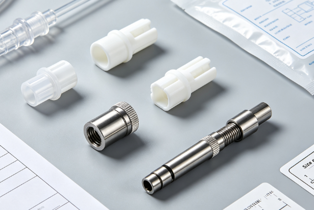
Grooving is a machining operation that creates narrow channels on workpieces. It is typically performed on CNC machines with dedicated cutting tools. It provides paths for threads and ensures precise fitting for O-rings and seals.
Grooving Process
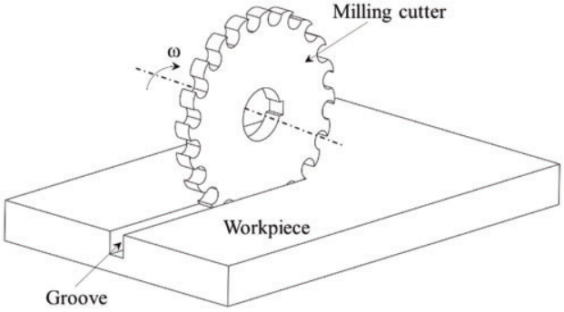
Grooving is a CNC turning process used to form long, narrow grooves on workpieces. It allows other geometric parts to move inside the grooved channels cut into the metal. The cutting dimension is determined by the width of the cutting tool. Multiple tool passes are required to produce wider grooves.
Purpose of Grooving
Grooving facilitates part joining and structural assembly. Grooved pipes fit seamlessly with sprinkler fittings, maintaining secure connections under water pressure. CNC machines with specialized cutting tools are widely used for grooving.
Grooving vs Turning
Grooving and turning are two distinct machining processes. creates narrow cuts with a depth matching the tool width. CNC turning removes material from rotating workpieces to produce cylindrical shapes.
Common Applications
Grooving is commonly used to manufacture retaining rings, seals, and fixing grooves. It is an essential process for fire protection systems, with grooved flanges widely applied in HVAC pipe connections. Further uses include water treatment systems, pipe locking, and sheet metal joints for barrels and assemblies.
Overview of Grooving Machines
Grooving machines work simply: rotary tools cut precise grooves into metal parts. Controlled grooving angle and depth deliver accurate sharp-angle features. CNC automates the process, with high-performance tools ensuring top machining precision.
Characteristics of Grooving Lathe Tools
The features of grooving lathe tools vary by type.
Types of Grooving Tools
There is a wide range of grooving tool types available.
Face Grooving Tools
Face grooving tools traverse workpiece surfaces on CNC lathes. Use shallow cuts for better stability; high-precision cutting fluid optimizes chip control and removal.
Internal Grooving Tools
These tools travel along the inner diameter of workpieces. Cutting fluid is used to ensure high material removal efficiency and effective chip control. The operation starts from the bottom of the hole and progresses forward to facilitate smooth chip evacuation.
External Grooving Tools
The tool moves radially along the outer side of the material. During grooving, material removal takes place precisely at the cutting edge.
Parting Tools vs Grooving Tools
Parting tools and grooving tools serve different purposes. tools split a workpiece into two separate pieces by cutting a narrow groove. By contrast, grooving only creates recessed channels on the workpiece surface.
Grooving Inserts
Grooving inserts are suitable for machining deep, narrow holes with long overhangs. They are ideal for applications where vibration and deflection are likely to occur.
Carbide Inserts
Best suited for abrasive and corrosive materials such as steel and cast iron. Capable of forming irregular holes on shafts and similar workpieces under semi-interrupted cutting conditions.
Tungaloy Inserts
High-performance inserts designed for heavy roughing operations. Ideal for forged, cast, and rough sawn raw stock.
Cutting Tools and Tool Wear
Common cutting edge tools used for grooving include hand milling cutters, milling cutter benches, circular saws, orbital saws, planers, cross chisels, table saw blades, and more.
Tool wear refers to the failure of cutting tools caused by high temperature, improper machining parameters, or incorrect operating procedures.
Material Influence on Grooving
Grooving yields different results depending on whether the material is soft or hard.
Stainless Steel
Stainless steel features high hardness and strong work hardening tendency, which accelerates tool wear. Grooving requires lower cutting speeds.
Aluminum Plate
Aluminum is ductile and easy to bend. Grooving serves aluminum for special structural designs beyond conventional machining.
Brass
Brass is ductile and highly machinable, supporting high-speed cutting and delivering excellent surface finish.
Titanium
Titanium has poor machinability, low stress‑strain ratio, and low elasticity, making it prone to deformation during grooving. Using textured tools reduces friction and improves machinability.
ABS Plastic
ABS is brittle and has low heat resistance. For quality grooving results, use milling cutters, triangular chamfer plates, or woodworking equipment suitable for grooving.
PC
PC is non-toxic, impact-resistant plastic, groovable by engraving, grooving and laser cutting.
POM
POM suits applications needing high precision, easy machining and strong deformation resistance. Grooves boost its bonding strength with other materials.
PTFE
Grooving on PTFE is similar to grooving on rubber (especially O‑rings). The only differences are narrower groove width and lower applied pressure due to the material’s higher rigidity.
Material Hardness and Groove Quality
Groove quality significantly affects material hardness, depending on material type and welding process.
- V‑grooves can increase hardness in the weld zone by up to 33%.
- Smaller welding grooves improve weld toughness and hardness.
- High heat input and slow cooling reduce hardness.
Electropolishing for Surface Finish
Electropolishing works on multi-groove surfaces, improving surface finish by up to 50% while preserving dimensional tolerances. Final finish depends on tolerance limits and material removal rate.
Precision Grooving Technology
Common practices for precision grooving involve multiple key factors.
Cutting Force and Vibration Control
Proper workpiece clamping and positioning effectively reduce vibration during grooving. Reasonably controlled cutting speed and low feed rate help improve surface finish and groove quality. A shallow cutting depth further minimizes vibration and cutting force.
Radial Depth of Cut
It measures the contact extent of the tool with the workpiece perpendicular to the axis, also known as cutting width. Groove quality largely depends on feed rate, cutting speed, and radial depth of cut.
Maximizing Tool Efficiency
To maximize tool efficiency, selecting suitable grooving tools and inserts is critical. Inserts shall be chosen according to workpiece material, groove geometry, and machining parameters.
Improving Groove Surface Finish
Get premium groove surface finish with proper tool and coolant selection, optimized cutting speed and feed rate, reasonable tool geometry and wiper edge tech, plus avoiding overly thin or oversized tools.
Grooving Operations on CNC Lathes
There are several steps involved in grooving operations on a lathe.
Setting Up a CNC Lathe for Grooving
First, securely clamp the workpiece and mark the grooving position.
Adjusting Lathe Parameters for Better Quality
Select and calibrate the grooving tool. Configure the CNC lathe and adjust the RPM settings. Input and run the machining program. After completing the grooving operation, clean up the setup and tools.
External Grooving vs Internal Grooving
External grooving and internal grooving differ in groove location and tool selection.
cuts channels on the outer part of the workpiece, moving along the outer diameter.
Internal grooving is performed inside the workpiece to form deep holes and cavities.
Deep Grooves: Challenges and Solutions
Deep groove machining faces multiple challenges. Poor chip evacuation, insufficient coolant penetration, tool wear, and incorrect machine setup may all lead to tool deflection and poor surface finish.
Effective solutions include using a flywheel to reduce vibration, adopting well-designed cutting tools, applying proper lubrication, ensuring precise alignment, and replacing bearings regularly.
Preventing Tool Wear in CNC Operations
To avoid tool wear during CNC machining, apply optimized cutting parameters, use suitable cutting fluid, select wear-resistant tool materials, and conduct regular tool wear inspection and monitoring.
Troubleshooting Grooving Issues
Below are common problems to check during grooving operations.
Chip Control Solutions
Optimize chip control with high-flow coolant, nonlinear tool paths, lateral offset tuning, matched speed and feed settings, small tool bars, narrow inserts, rigid clamping, thick blades, and large-diameter grooving tools.
Managing Tool Vibration
The best way to reduce tool vibration is to adopt a dual-contact spindle and tool holding system, which effectively improves groove dimensional accuracy.
Surface Finish Optimization
To achieve superior surface finish on grooves, use high-speed cutting tools, proper tool retraction, optimized tool nose radius, wiper-edge inserts, eliminate dwell and pause time, and apply a larger tool rake angle.
Reducing Tool Chatter and Wear
To minimize tool chatter and wear, use rigid tools and tool holders, keep short tool overhang, adopt low cutting force and shallow depth of cut, apply anti-vibration bars, and follow proper machine arc generation settings.
Precision Grooving Technology
Deep Face Grooving
Deep face grooving runs 20–25 mm deep, machining axial-aligned grooves on part end faces.
Achieving Smooth External Grooves
Shafts and pipes often require external groove machining during manufacturing. To obtain smooth external grooves, prioritize excellent surface finish for precise fitting. Multiple machining passes are needed for wider grooves.
Optimizing Groove Geometry
The following key factors need to be considered to achieve optimized groove geometry.
Multi-Edge Grooving Inserts
Multi-edge grooving inserts are naturally suitable for a wide range of grooving operations, including CNC turning, grooving, threading, profiling, and parting.
Custom Grooving Tool Configurations
Custom grooving tools meet unique design needs beyond standard options. They cut cycle time, enable special-angle inserts and simplify programming.
How to Choose the Right Grooving Tool
Choose grooving tools by material type, groove shape, chip control, machine performance and insert width。
Key Considerations
The main factors to take into account are as follows:
Tool Material
The selection of tools such as carbide and Tungaloy depends on workpiece material type, cutting conditions, tool holder compatibility, groove geometry, diameter range, and most importantly, budget.
Tool Compatibility and Geometry
Tool compatibility must match the workpiece material. The tool geometry, including cutting edge, rake angle and relief angle, should be optimized to achieve better chip evacuation and superior surface finish.
Choosing Between Internal and External Tools
The selection of external and internal grooving tools depends on tool size and shape, material characteristics, grooving method, coolant selection, feed rate, and cutting control.
Tool Selection by Workpiece Material
Material impact on tool performance is a critical factor. Hard materials require durable, high-rigidity tools such as carbide tools. Ductile materials can be easily machined with high-carbon steel or other standard tools with lower wear resistance.
Tools for Different Grooving Operations
A variety of tools are available for different grooving tasks, including parting tools, threading tools, CNC turning tools, O-ring grooving inserts, small internal grooving tools, and knurling tools.
Improve Grooving Efficiency and Quality
Multiple factors affect the improvement of grooving efficiency and quality.
Optimize Feed Rate and Cutting Speed
Start grooving at a low feed rate and gradually increase it to enhance chip control and evacuation, achieving ideal grooving results. Matching cutting speed with the feed rate helps extend tool service life.
Achieve Consistent Groove Dimensions
Groove dimensions can be measured with tools such as rulers and calipers. For larger inner diameters, use an O-Sizer or Pi-Tape. O-ring calculators such as ERIKS and Ceetak are also available for reference.
Reduce Tool Wear Through Proper Setup
To minimize tool wear, optimize cutting parameters, apply cutting fluids and lubricants, reduce cutting speed, avoid re-cutting chips, and control tool deflection.
Achieve Better Results with Cutting Fluid
Cutting fluid reduces friction, extends tool life, and improves machining accuracy. It effectively lowers tool wear while boosting grooving precision.
Improve Groove Surface Finish
High-quality surface finish can be achieved by adopting optimized insert geometry and wiper edge technology. Inserts must maintain tight tolerances with accurate radius and width. For mass production, inserts require precise profile and chamfer design.
FAQ
What is the difference between a slot and a groove?
A slot is a straight elongated hole with radiused edges. A groove is cylindrical with cutouts on the outer or inner diameter.
What machines can be used to machine grooves on metal?
Machines for metal grooving include CNC machining centers, lathes, milling machines, dedicated grooving machines, and gear cutting tools.
How to prevent tool chatter during grooving operations?
Tool chatter can be minimized by using rigid tools and tool holders and maintaining consistent cutting pressure.
What material is best for grooving tools?
Carbide inserts are the best choice for grooving tools, featuring high wear resistance, excellent heat resistance, and versatile performance for machining a wide range of materials.
How to improve the surface finish of grooves?
Better surface finish can be achieved by adopting higher cutting speeds, using well-balanced tools to reduce vibration, applying machines with good damping performance, and utilizing chip-breaker grooves and wiper edges.
Do grooving tools require coating for better performance?
Coatings extend the service life of grooving tools, optimize cycle time, and improve surface finish.