
Published:Zorapid.Ltd
Core Value & Typical Racing Applications
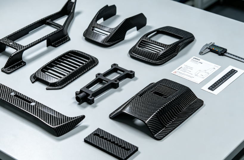
Carbon fiber reinforced FDM (Fused Deposition Modeling) delivers ultra-light, rigid, rapidly iterable thermoplastic composite parts for circuit racing, rally, drift, F1, GT, and amateur track vehicles. Unlike traditional autoclave prepreg carbon fiber, CF-FDM eliminates custom mold costs, enables complex organic/lattice aerodynamic geometry, and cuts iteration lead times from weeks to hours — a decisive competitive edge for race teams testing revised setups mid-season.
Key Performance Benefits for Racing
- 30–55% weight reduction vs solid aluminum brackets, cutting unsprung mass, rotational inertia, and vehicle curb weight
- High stiffness-to-weight ratio to reduce chassis flex under high G cornering, acceleration and braking loads
- Thermal resistance to survive underhood exhaust, brake duct, and ECU bay heat
- Rapid design iteration for aerodynamic tweaks, airflow testing, and suspension prototype parts
- Chemical resistance to race fuels, brake fluid, oil, and cleaning solvents
- Corrosion-free, no rust degradation like steel/aluminum track hardware
Common Racing CF-FDM Components
- Aerodynamic parts: Small spoiler endplates, diffuser fins, brake cooling duct housings, air intake splitters, vortex generators
- Suspension & chassis brackets: Damper mounts, anti-roll bar spacers, suspension pick-up shims, lightweight mounting lugs
- Powertrain & cooling: Radiator mounts, oil catch tank brackets, custom thermostat housings, battery tray inserts
- Electronics & cockpit: ECU enclosures, wiring looms clamps, steering wheel internals, switch gear housings, radio mounts
- Jigs & pit tooling: Composite layup molds, alignment fixtures, wheel torque guide tools, pit stop custom holders
Carbon Fiber FDM Filament Material Grades for Motorsport
All CF-FDM racing filaments use short chopped carbon fibers (10–35% wt loading) embedded in high-performance thermoplastic matrices; fiber aligns along extrusion paths, creating directional anisotropic strength. Continuous carbon fiber inlay FDM is used for high-load structural brackets where uniaxial stiffness is critical.
1: CF-PETG (Entry-Level Aero & Low-Load Cosmetic Parts)
- CF loading: 10–15% short carbon fiber
- HDT: 70–80°C, matte rigid surface, minimal warpage, low printing difficulty
- Best for: Exterior aerodynamic fins, non-structural duct covers, cockpit trim
- Limitation: Not suitable for sustained underhood heat above 80°C, lower tensile modulus than nylon variants
2: PA6-CF / PA12-CF (General Racing Structural Standard)
- CF loading: 15–35% (Nylon 12CF 35% is industrial benchmark)
- HDT: 110–130°C, excellent fuel/oil resistance, high tensile modulus, good layer adhesion
- Best for: Suspension brackets, ECU housings, cooling mounts, pit tooling
- Limitation: Absorbs ambient moisture; requires full drying before printing to avoid layer delamination
3: High-Temp PAHT-CF / PPA-CF (Underhood & High-Temp Zones)
- CF loading: 15–25% carbon fiber
- Continuous operating temp: 180–220°C, low moisture uptake, minimal thermal creep
- Best for: Parts adjacent to exhaust manifolds, brake caliper cooling ducts, turbo ancillary brackets
- Limitation: Requires high-temperature enclosed build chambers (≥80°C ambient) to prevent warpage
4: PC-CF (High-Impact Crash & Vibration Critical Parts)
- Highest stiffness among standard FDM composites, excellent impact toughness
- HDT ~125°C, abrasion resistant
- Best for: Steering wheel core inserts, crash protection small brackets
- Limitation: High shrinkage, requires heated chamber and controlled cooling cycles
5: PEEK-CF (Top-Tier Professional Motorsport / F1)
- 10–20% CF reinforced PEEK, continuous use 240°C, ultra-high fatigue strength
- Used exclusively for elite F1/GT race car flight-critical small components
- Limitation: Extremely high material & machine cost, specialized high-temp industrial printers only
Material Selection Rule of Thumb
- Exterior aero / low heat: CF-PETG
- General structural brackets / ECU: PA12-CF 35%
- Underhood high heat near exhaust: PAHT-CF
- Elite F1 structural high-temp components: PEEK-CF
Industrial FDM Machine Hardware Requirements for Racing Parts
Desktop consumer FDM printers cannot produce consistent, load-bearing race components. Industrial composite FDM systems are mandatory for homologated track use:
- Enclosed heated build chamber (60–120°C) – eliminates warpage and layer separation for nylon/PAHT CF materials
- Hardened tungsten carbide nozzles (0.4–0.8mm) – short carbon fiber rapidly abrades standard brass nozzles
- Filament dryers integrated inline – maintains moisture <0.02% for nylon-based CF filaments
- High-flow extruders with consistent retraction control – prevents under-extrusion and voids in thick structural walls
- Closed-loop temperature monitoring for hotend, chamber, and build plate
- Optional continuous carbon fiber inlay head – for targeted unidirectional reinforcement on high-stress axes
- Large-format build volume for full-size duct and bracket assemblies
- Z-axis precision ±0.01mm to maintain uniform layer bonding under cyclic race vibration
Critical DFM Rules Optimized for CF-FDM Race Components
CF-FDM is anisotropic; strength follows print layer extrusion paths. All design rules balance lightweight lattice optimization, layer adhesion, and FIA structural safety standards.
Wall Thickness & Rib Rules
- Minimum solid wall: 1.2mm (PA-CF / PC-CF); 1.5mm for high-load suspension lugs
- Internal support ribs: Minimum 1.0mm thickness, spaced 4–6mm apart to reduce weight without flex
- Avoid single thin unsupported walls over 20mm span; add cross bracing or gyroid infill reinforcement
Infill Strategy (Lightweight Core for Racing)
- Low-load aero parts: 15–25% gyroid infill – minimal weight, uniform vibration dampening
- Medium-load brackets (cooling mounts): 40–60% rectilinear infill aligned to primary load direction
- High-stress suspension lugs: 80–100% solid infill + continuous carbon fiber unidirectional inlay along tension axes
- Gyroid infill preferred over linear grid: eliminates directional weak points under multi-axis G-forces from cornering/braking
Overhang & Support Geometry
- Self-support overhang limit ≤45°; steep angles require soluble PVA support (remove fully via DI water wash to avoid residual stress risers)
- Eliminate deep blind pockets: trapped support residue creates micro-cracks under cyclic race loads
- All external fillets minimum R=0.8mm – sharp corners concentrate tensile stress and trigger layer delamination under vibration
Hole, Boss & Fastener DFM (Race Hardware Mounting)
- Minimum hole diameter: 2.0mm; tapped holes add internal boss thickness ≥2.5mm around bore to prevent thread splitting
- Press-fit insert bosses: Add 0.3mm interference allowance, full circular fillet at boss base
- Align print extrusion paths parallel to bolt tension loads to maximize pull-out strength
- Avoid thin-walled threaded bosses exposed to repeated torque cycling during pit stops
Anisotropy & Fiber Alignment Core Rule
Design CAD load paths to match print raster direction:
- Primary tension/compression loads run along X/Y extrusion lines (highest tensile strength)
- Z-axis (layer bonding) is the weakest plane – never orient critical tension loads vertically through stacked print layers
- For multi-axis loading: alternate ±45° raster per layer to create quasi-isotropic laminate behavior
Aerodynamic Thin-Wall DFM for Ducts & Vortex Generators
- Uniform wall thickness 1.2–1.8mm to avoid differential shrinkage warping airflow geometry
- Internal smooth radii to reduce turbulence; post-print epoxy sealing eliminates layer line surface roughness
- Hollow lattice core to cut weight without sacrificing rigidity at high track speeds
Printing Process Parameters & Quality Stabilization Workflow
Pre-Print Material Preparation (Make-or-Break Step for Nylon CF)
- Dry PA-CF / PAHT-CF filament at 80°C for 4–8 hours until moisture <0.02%
- Store all CF spools in sealed heated dryers between batches to prevent water absorption
- Filter recycled filament scrap to remove carbon fiber dust and broken filament segments
Standard Industrial CF-FDM Print Profiles (PA12-CF 35%)
- Hotend temp: 260–280°C
- Enclosed chamber temp: 70–80°C
- Build plate temp: 100–110°C
- Layer height: 0.15–0.25mm (0.15mm for high-precision aero surfaces)
- Print speed: 40–60 mm/s (slower speed improves fiber alignment and layer fusion)
- Retraction distance: 2–3mm to eliminate stringing on fine aerodynamic features
Batch Quality Control Mid-Production
- First article coupon tensile test at start of each filament spool batch
- Real-time layer gap monitoring; pause print if under-extrusion voids appear
- Post-print 24-hour ambient stress relief before machining/finishing to eliminate shrinkage drift
Post-Processing, Surface Sealing & FIA Compliance Finishing
Raw CF-FDM parts have visible layer lines, micro-porosity between extruded beads, and exposed chopped carbon fiber dust — critical to seal for race use to prevent fuel absorption, water ingress, and micro-crack propagation under vibration.
Step 1: Support Removal & Light Deburr
- Dissolve PVA soluble supports in heated DI water bath; ultrasonic clean to remove residual support micro-filaments
- Light glass bead blast (low pressure) to smooth layer ridges without cutting into surface resin matrix
Step 2: Epoxy Resin Sealing (Mandatory for All Track Racing Parts)
Two-part low-viscosity aerospace epoxy saturates micro voids between print layers:
- Dip or brush coat full part
- Vacuum degas to pull epoxy into inter-bead gaps
- Cure at 60°C for 4 hours Result: Zero fluid absorption, uniform smooth aerodynamic surface, improved inter-layer shear strength by 30–40%, prevents carbon fiber dust shedding in engine bay airflows
Step 3: Secondary Finishing Options
- Light sand + clear polyurethane topcoat: UV resistance for exterior aero parts exposed to track sunlight
- Machined mounting faces: CNC mill critical bolt boss surfaces for precise alignment to chassis
- Heat shield coating: Silicone thermal barrier paint for underhood high-temp components
Step 4: FIA Homologation Marking
Permanent fiber laser marking of part number, material grade, and batch test data on non-load-bearing surfaces (no deep engraving on structural zones to avoid stress notches)
Performance Comparison: CF-FDM vs Prepreg CFRP vs 6061-T6 Aluminum
| Metric | 35% PA12-CF FDM | Autoclave Prepreg CFRP Unidirectional | 6061-T6 Aluminum |
|---|---|---|---|
| Density (g/cm³) | 1.25 | 1.55 | 2.70 |
| Weight vs Aluminum (Same Stiffness) | 52% lighter | 62% lighter | Baseline |
| Tensile Modulus (GPa) | 8–12 | 140–160 | 69 |
| Lead Time Single Prototype | 4–12 hours | 7–14 days (mold + layup + autoclave) | 3–5 days CNC |
| Complex Organic Aero Geometry | Unlimited | Restricted by mold draft angles | Limited by milling tool reach |
| High-Temp Continuous Use | Up to 130°C (PA12-CF) | 180°C (epoxy prepreg) | 220°C |
| Iteration Modification Cost | Near-zero (reprint CAD) | High (remake autoclave mold) | Medium (reprogram CNC) |
| Cyclic Vibration Fatigue Life | Good (sealed epoxy finish) | Excellent | Poor (fatigue crack risk on thin brackets) |
| Per-Part Low Volume Cost (1–5 units) | Low | Very High | Medium |
Core Tradeoff Summary
- CF-FDM wins for rapid iteration, low small-batch cost, ultra-complex lightweight lattices and aerodynamic test components
- Prepreg CFRP dominates primary monocoque chassis, full-size wing structures where maximum uniaxial strength is required
- Aluminum is retained for extreme high-temp exhaust mounting hardware where thermoplastics cannot survive
Common FDM Defects in Racing Parts & Root-Cause Solutions
- Inter-Layer Delamination under Vibration (Biggest Race Failure Risk) Root: Moist nylon filament, insufficient chamber heat, too-fast print speed, un-sealed micro voids Fix: Full pre-drying, raise enclosed chamber temperature, reduce print speed, vacuum epoxy seal post-print
- Part Warpage & Dimensional Shrinkage Drift Root: Unheated build chamber, uneven cooling, thick mass concentration in single zones Fix: 70°C+ enclosed chamber, balanced wall/lattice design, 24hr stress relief post-print before machining
- Voids & Porosity Inside Structural Lugs Root: Low filament flow rate, clogged carbide nozzle, inconsistent retraction Fix: Replace worn carbide nozzle, increase hotend temperature, run slow uniform extrusion profiles
- Surface Fiber Shedding / Fuel Absorption Root: Unsealed raw print micro-gaps between extruded beads Fix: Full vacuum epoxy saturation sealing process mandatory for all track-installed components
- Threaded Boss Splitting Under Torque Root: Insufficient wall thickness around bore, vertical Z-axis layer alignment across bolt load Fix: Increase boss wall to ≥2.5mm, orient print raster parallel to bolt tension, add circular base fillets
Validation, Mechanical Testing & FIA Homologation Documentation
Race sanctioning bodies (FIA, SRO, SCCA) require full material and part validation before track use:
Mandatory Test Suite for Structural CF-FDM Brackets
- Tensile coupon test (X/Y print plane + Z-axis layer bond strength)
- Cyclic vibration fatigue test (100,000 cycles at race track G-force load spectrum)
- Thermal cycling test (-20°C to 130°C, 50 cycles) to validate no dimensional creep
- Fluid immersion test (brake fluid, race gasoline, motor oil, 72hr soak) – measure weight gain to confirm epoxy sealing effectiveness
- Static pull-out torque test for threaded mounting bosses
Required Documentation Package
- Filament material MTR with carbon fiber loading, tensile modulus, HDT certification
- Print parameter batch log (chamber temp, layer height, infill percentage)
- Post-processing epoxy seal process record
- Full mechanical test report with coupon failure photos
- Dimensional CMM layout report of critical mounting datum features
- Batch traceability log linking CAD revision, print run, and test results
Cost & Lead-Time Advantages for Race Teams
- No custom mold investment: Prepreg CFRP requires CNC master plug and autoclave mold; CF-FDM prints directly from CAD
- Same-day design iteration: Aerodynamic tweak CAD overnight, print revised duct for track testing next morning
- Low small-batch overhead: 1–10 prototype brackets cost 60–80% less than CNC aluminum or autoclave carbon
- Integrated lightweight lattice geometry without secondary machining cost
- Reduced pit stop weight savings: Cumulative mass reduction across dozens of small brackets improves lap time and tire wear
- In-house manufacturing capability: Teams eliminate outsourcing lead times from external composite suppliers during race season development cycles
Quick Audit Checklist for Racing CF-FDM Production
Industrial enclosed heated-chamber FDM printer with carbide CF nozzles
Filament fully dried and moisture controlled <0.02% before printing
Material grade matched to operating temperature zone (PAHT-CF for underhood)
DFM compliant wall thickness ≥1.2mm, all internal/external radii R≥0.8mm
Infill aligned to primary load axes; high-stress lugs use ≥80% solid infill
Soluble support fully removed + ultrasonic clean post-print
Full vacuum epoxy sealing process applied to eliminate micro voids
Complete mechanical fatigue, thermal, and fluid immersion test data on file
Batch traceability, print parameter logs, and CMM dimensional reports archived
Permanent laser part marking without engraving structural load surfaces
24-hour ambient stress relief before CNC secondary machining
FAQ
Can CF-FDM fully replace autoclave prepreg carbon fiber on race cars?
Not for primary load-bearing monocoque chassis, full front/rear wings, or crash safety structures. It is ideal for secondary brackets, aerodynamic test fins, cooling ducts, ECU housings, and custom pit tooling where rapid lightweight iteration is prioritized over maximum uniaxial tensile strength.
Why is epoxy sealing mandatory for all track racing CF-FDM parts?
Raw printed CF-FDM has micro gaps between extruded plastic beads. Without epoxy saturation, race fuel, brake fluid, and water penetrate voids, expanding under thermal cycling and creating internal micro-cracks that fail under high vibration loads. Sealing also stops loose carbon fiber dust contaminating engine air intake systems.
What material should I choose for parts mounted close to exhaust manifolds?
PAHT-CF or PPA-CF high-temperature carbon fiber nylon; PA12-CF will warp and creep under sustained temperatures above 110°C. CF-PETG is completely unsuitable for underhood zones.
Why is the Z print layer plane the weakest direction for CF-FDM?
Carbon fibers only align along horizontal X/Y extrusion paths; vertical layer bonding relies solely on melted thermoplastic matrix with no fiber reinforcement across layers. Designers must avoid placing critical tension loads vertically through stacked print layers.
Is CF-FDM legal under FIA race regulations?
Yes, for secondary non-chassis structural and aerodynamic components, provided full material certification, mechanical fatigue testing, and epoxy sealing validation documentation are submitted for homologation. Primary crash/chassis structures remain restricted to autoclave prepreg CFRP per most FIA series rules.
How much weight can CF-FDM brackets save compared to aluminum equivalents?
Typically 45–55% weight reduction for identical stiffness specifications, drastically cutting unsprung mass and rotational inertia on suspension, brake, and wheel ancillary components.


