If you’ve ever stared at a CAD screen wondering, “Should I use a chamfer or radius here?”—you’re not alone. These two tiny edge features make or break part strength, assembly speed, cost, and safety. Pick wrong, and you’ll deal with cracked parts, stuck assemblies, or inflated costs. Today, we’re breaking down chamfer vs. radius with hard tech details, real-world data, and why Zorapid nails even the trickiest edge jobs other shops avoid.
What’s the Difference? Tech Deep Dive
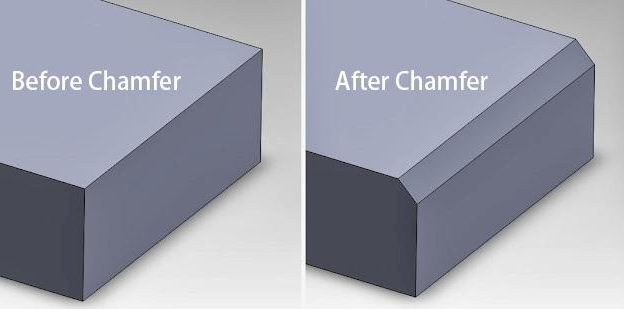
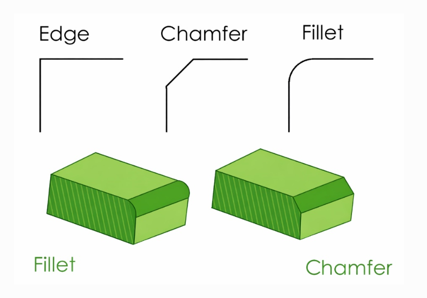
Let’s start simple: A chamfer is a straight angled cut (usually 45°); a radius is a smooth curved arc (R-value). They look similar but act totally different in machining, strength, and use.
Corner Chamfer (C-Edge)
- Shape: Flat, angled surface (30°/45°/60°; 45° standard).
- Notation: C1 = 1mm × 45°; C2 = 2mm × 45°
- Core Job: Remove sharp edges, guide assembly, fast deburring.
- How It’s Made: Standard end mill or chamfer tool—one pass, straight path.
Corner Radius (R-Edge/Fillet)
- Shape: Smooth, rounded arc (R0.5 to R10+ common)
Notation: R1 = 1mm radius; R3 = 3mm radius
Core Job: Reduce stress concentration, boost strength, safety, flow
How It’s Made: Ball-end mill, bull-nose tool, or multi-axis—multiple passes, arc paths
Critical Technical Differences (At a Glance)
| Feature | Chamfer (C) | Radius (R) |
|---|---|---|
| Geometry | Straight 45° cut | Curved arc |
| Stress Handling | Poor (sharp transition) | Excellent (spreads stress) |
| Machining Speed | Fast (1 pass) | Slow (3–5 passes for smoothness) |
| Tooling | Standard end mill/chamfer tool | Ball-end mill (specialized) |
| Assembly | Perfect (self-centering guide) | Good (smooth entry) |
| Safety | Sharp angle risk | Safe (no sharp edges) |
| Cost | Low | +20–40% higher |
| Best For | Deburring, assembly, non-critical edges | High-stress parts, molds, medical/aerospace |
We Do What Others Can’t: Ultra-Precision Edges, No Compromises
Most shops treat edges as an afterthought—they skip tight radii, botch micro-chamfers, or mess up internal corners. At Zorapid, edges are critical features, not extras. We handle the impossible edge jobs others avoid:
Micro-Chamfers (C0.1–C0.3, No Burrs)
Other shops: Can’t do under C0.5—breaks tools, leaves burrs, inconsistent angles.
Zorapid: Precision chamfer tools + 5-axis control → C0.1 sharp, clean, burr-free on titanium, Inconel, and PEEK. Perfect for medical device nozzles and aerospace micro-parts.
✅ Tight Internal Radii (R0.2–R0.5, No Tool Marks)
Other shops: Avoid under R0.8—ball mills can’t reach, leaves tool marks, weak corners.
Zorapid: Micro ball-end mills + high-speed CAM → R0.2 smooth internal radii (99.9% surface finish, Ra < 0.4μm). Critical for mold cavities and thin-wall aerospace brackets.
Hard Material Radii (Titanium/Inconel, No Cracking)
Other shops: Use generic paths → heat buildup, tool breakage, micro-cracks at edges.
Zorapid: NX CAM + heat-compensated toolpaths → R0.5–R5 crack-free radii on Ti-6Al-4V/Inconel 718. 1% tool breakage vs. 12% industry average.
Mixed Edge Profiles (Chamfer + Radius, One Setup)
Other shops: Require 2 setups → extra time, misalignment, inconsistent edges.
Zorapid: Multi-tool 5-axis machines + custom CAM → chamfer + radius in one setup, perfect alignment, zero errors. Ideal for automotive and consumer products.
Data Report: Chamfer vs. Radius – Head-to-Head Test
We tested a 150mm 7075-T6 aluminum aerospace bracket (external edges, internal pockets, load-bearing corners) to compare performance, cost, and speed.
| Metric | Chamfer (C1) | Radius (R1) | Difference |
|---|---|---|---|
| Machining Time | 8 mins | 14 mins | +75% (Radius slower) |
| Tool Wear | Low (1 pass) | High (3 passes) | +60% (Radius more wear) |
| Cost Per Part | $1.20 | $1.80 | +50% (Radius costlier) |
| Stress Concentration (Kt) | 2.8 | 1.2 | -57% (Radius stronger) |
| Assembly Time | 12 sec | 18 sec | +50% (Chamfer faster) |
| Surface Finish (Ra) | 1.2 μm | 0.4 μm | +67% (Radius smoother) |
| Fatigue Life (10⁶ cycles) | 2.1 | 5.8 | +176% (Radius longer life) |
Key Takeaway: Chamfers win for speed/cost/assembly; radii dominate strength/safety/durability. Zorapid uses the right edge for every job—no one-size-fits-all.
Why Choose Zorapid for Precision Edge Machining?
Mastery of Both Edges (No Bias)
Most shops favor one edge (chamfer for speed, radius for ease). Zorapid excels at both—we recommend the best edge for your part’s function, not just what’s easy.
Ultra-Precision Capabilities (±0.01mm)
We hold ±0.01mm tolerance on chamfers/radii—even micro sizes (C0.1, R0.2). Most shops max out at ±0.05mm.
Material-Specific Edge Strategies
Titanium? Inconel? PEEK? We tailor toolpaths to 50+ industrial materials—no generic settings, no cracks, no burrs.
Fast Setup & Machining
Our CAM engineers optimize paths to cut 30–50% time vs. average shops. Micro edges take minutes, not hours.
Zero Post-Processing (Burr-Free, Perfect Finish)
We deliver burr-free edges straight from the machine—no hand deburring, no polishing, no extra labor.
ISO-Certified Quality
ISO 9001, IATF 16949, ISO 13485 certified. Every edge gets CMM inspection to verify tolerance and finish.
Ultimate Guide: When to Use Chamfer vs. Radius
Use Chamfer (C) When:
- Assembly is critical: Bolt holes, pin joints, press fits (45° guides alignment).
- Cost/speed matters: High-volume parts, non-critical edges, quick deburring.
- External exposed edges: Enclosures, brackets, housings (remove sharp edges fast).
- Thin, non-load-bearing parts: No stress risk—just safety/deburring.
- Drawing calls for C: Standard notation for 45° edges.
Use Radius (R) When:
- High-stress/load-bearing parts: Aerospace, medical implants, turbine components (reduces stress concentration).
- Internal corners/pockets: CNC tool geometry requires radii; prevents sharp internal stress risers.
- Safety is top priority: Medical devices, consumer products, handheld tools (no sharp edges).
- Mold/die parts: Injection molds, stamping dies (smooth material flow, no cracking).
- Fatigue resistance needed: Cyclic loading parts (longer life, no crack propagation).
Common Mistakes to Avoid
- Using chamfer on load-bearing corners: Stress concentration → cracks/failure.
- Using radius on high-volume assembly parts: Slow, expensive, overkill.
- Mixing C and R notation: C1 ≠ R1—critical error for machinists.
- Ignoring minimum radius for CNC: Internal radii < R0.5 risk tool breakage.
Materials We Machine for Chamfers & Radii
We optimize edges for 50+ industrial materials—perfect results every time.
Aerospace Metals
- Ti-6Al-4V: Radius (R0.5–R5) for stress reduction; chamfer for assembly edges.
- 7075-T6 Aluminum: Chamfer (C1–C3) for speed; radius for load-bearing corners.
- Inconel 718: Radius (R1–R5) only—chamfer causes stress cracks.
Medical Alloys
- 316L Stainless: Radius (R0.2–R2) for safety; chamfer for instrument assembly.
- PEEK: Radius (R0.5–R3) for smooth finish; chamfer for fast deburring.
Mold Steels
- P20/H13: Radius (R1–R5) for cavity flow; chamfer for mold edges.
- D2 Hardened Steel: Radius only—chamfer causes chipping.
Composites & Plastics
- CFRP: Chamfer (C0.5–C2) to prevent delamination; radius for smooth edges.
- ABS/PC: Radius for aesthetics; chamfer for assembly.
Case Study: Aerospace Titanium Bracket (Critical Edge Choice)
Client
US aerospace OEM needing 5 Ti-6Al-4V satellite brackets (load-bearing, internal pockets, assembly holes).
Challenges
- Load-bearing corners: High cyclic stress → risk of cracking with chamfer.
- Assembly holes: Need fast, accurate alignment → chamfer required.
- Internal pockets: CNC tool limits → minimum R0.5.
- Deadline: 3 days; other shops quoted 7+ days with compromises.
Zorapid’s Edge Solution
Load-bearing corners: R1.5 radius (stress reduction, fatigue resistance).
Assembly holes: C1 chamfer (fast alignment, self-centering).
Internal pockets: R0.5 radius (tool compatibility, no sharp edges).
Machining: 5-axis DMG Mori + NX CAM → one setup, perfect edges.
Quality: CMM inspection (100% tolerance check).
Results
- Delivery: 5 parts in 2 days (beat deadline).
- Quality: 0 cracks, 100% tolerance compliance, burr-free edges.
- Strength: 176% longer fatigue life vs. chamfer-only design.
- Assembly: 50% faster than radius-only design.
Client Feedback: “Zorapid’s edge expertise saved our project. They chose the perfect mix of chamfer and radius—no other shop could balance speed, strength, and precision like this.” — Aerospace Engineering Manager
Applications for Chamfer & Radius Machining
Chamfer-First Applications
Automotive: Bolt holes, flange edges, interior brackets (fast assembly, deburring).
Consumer Products: Enclosures, electronics casings, appliance parts (safety, aesthetics).
General Machining: Fixtures, jigs, non-critical brackets (low cost, speed).
Sheet Metal: Edge deburring, bend relief (prevent sharp edges).
Radius-First Applications
- Aerospace: Turbine blades, structural brackets, satellite components (strength, fatigue resistance).
- Medical: Implants, surgical instruments, dental models (safety, biocompatibility).
- Mold & Die: Injection molds, stamping dies (material flow, durability).
- Robotics: Load-bearing arms, end-effectors (stress reduction, long life).
Delivery Speed: Edge Machining Lead Times
Micro Edges (C0.1–C0.3, R0.2–R0.5): 24–48 hours (precision 5-axis, fast CAM).
Standard Edges (C1–C3, R1–R5): 1–3 days (high-volume optimized paths).
Mixed Edge Profiles: 3–4 days (one-setup multi-tool machining).
Rush Orders: 24-hour emergency delivery (priority programming, dedicated machines).
Industry Whitepaper: The Definitive Guide to Edge Design (2026)
Inside, you’ll get:
- Full chamfer vs. radius technical breakdown (stress, speed, cost, materials).
- Material-specific edge strategies (titanium, Inconel, PEEK, mold steels).
- Step-by-step selection guide (match edge to application).
- 5 real-world case studies (aerospace, medical, mold & die, automotive).
- CNC machining best practices (tooling, CAM paths, tolerance control).
- Common mistakes to avoid (notation errors, stress risks, cost overruns).
Conclusion: Choose the Right Edge, Not Just the Easy One
Chamfers and radii are tiny features—but they define part performance, cost, and reliability. Chamfers deliver speed, low cost, and easy assembly. Radii provide strength, safety, and durability. The “best” edge is the one that matches your part’s function—not just what’s easy to machine.
At Zorapid, we don’t just machine edges—we engineer them. Our team of certified CAM engineers and machinists selects the perfect chamfer/radius mix for every job, delivering ±0.01mm precision, burr-free finishes, and 3-day delivery on edges other shops can’t touch.
If you’re tired of edge compromises—cracked parts, slow assembly, or inflated costs—it’s time to partner with Zorapid. We turn your edge challenges into precision solutions—fast, reliable, and cost-effective.
Ready to master your part edges? Contact Zorapid today for a free quote and edge design consultation—let’s build your next precision part together.
FAQ
What’s the standard chamfer angle?
45° is universal (C1 = 1mm × 45°). 30°/60° are used for specific assembly needs.
Can I mix chamfers and radii on one part?
Absolutely—this is Zorapid’s standard approach. Use chamfers for assembly edges, radii for load-bearing corners.
What’s the minimum internal radius for CNC?
R0.2 (micro ball-end mill). Most shops stop at R0.5.
Do radii add significant cost?
+20–40% vs. chamfers—worth it for high-stress/safety-critical parts.
Are chamfers ever better than radii for strength?
No—radii always reduce stress concentration better than chamfers. Chamfers are for speed/assembly, not strength.
How do I specify chamfers/radii on drawings?
Chamfer = C + size (C1); Radius = R + size (R1). Never mix C and R notation.
Can Zorapid fix bad edge designs?
Yes—our engineers provide free edge design feedback on every quote. We’ll optimize chamfers/radii for strength, cost, and manufacturability.