Published by Zorapid
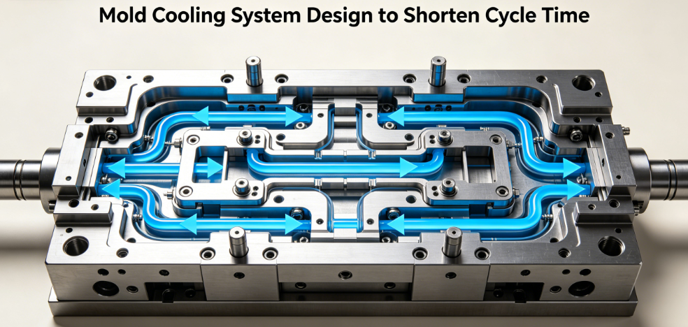
If you’re stuck with slow mold cycles, low daily output, warped parts, or constant sink marks—your cooling system is almost always the root culprit.
Cooling takes up 60–80% of every full injection molding cycle. Most standard mold shops only rely on basic straight gun-drilled water lines, which can’t wrap around ribs, deep bosses, curved cavities or thin-walled complex geometries. Hot spots linger, cooling time balloons, and your hourly production volume plummets.
At Zorapid, we build fully optimized cooling systems combining Moldflow thermal simulation, hybrid conventional cooling, and SLM 3D printed conformal cooling inserts. We cut total cycle times by 20–65% for automotive, medical, electronics and consumer plastic molds, while slashing reject rates from uneven heat distribution.
This complete deep dive breaks down cooling mechanics, side-by-side competitor gaps, exclusive Zorapid proprietary cooling solutions, mold steel thermal material comparisons, real production case data, market trends, delivery timelines, and all common client questions.
Professional Process & Technical Deep Dive
Core Thermal Failure Logic of Standard Drilled Cooling
Traditional straight channels have one fatal limitation: drill bits only move in linear paths. They cannot stay at a uniform 1.5–2mm distance from cavity surfaces on curved, ribbed, deep core parts. The heat transfer path becomes 3–5x longer on thick accumulations of plastic, creating persistent hot zones that dictate your entire cooling timer—even if 95% of the part cools fast.
Standard shops fix this by just adding extra cooling time, not reworking the channel layout. The result: longer cycles, higher energy bills, and heavy defects like warpage, sink marks, internal stress and inconsistent dimensional tolerance.
Zorapid Full-Stage Cooling Optimization Workflow (10-Step Thermal Design Standard)
- DFM Thermal Pre-Analysis: Map all thick ribs, bosses, deep draw hot spots from client CAD before machining
- Moldflow Multi-Physics CFD Simulation: Run 3+ thermal iterations to map cavity temperature differential (ΔT)
- Dual Cooling Layout Matching: Straight drilled primary lines for flat areas + SLM conformal inserts for complex hot zones
- Channel Parametric Design: Control channel diameter, pitch, cavity standoff distance (1.8–2.2mm uniform gap)
- TPMS Lattice Auxiliary Cooling for ultra-thin deep cores (Zorapid exclusive design)
- High-Conductivity Heat Sink Inserts (BeCu beryllium copper) stacked on concentrated heat zones
- Balanced Turbulent Flow Manifold Design: Eliminate dead coolant pockets that stall heat removal
- SLM Metal Printing of conformal inserts with 99.7% density (no internal leakage risk)
- Post-Print Stress Relief + CNC Precision Finishing + SPI polishing
- Real-World Thermal Validation Test: Record actual cycle time & cavity temperature data for client reports
Generic Mold Maker Simplified Cooling Workflow
- Skip upfront Moldflow thermal simulation → blind channel layout based on designer experience
- Only straight drilled channels; no conformal inserts even for complex thick-wall geometries
- Random channel spacing, inconsistent standoff distance from cavity → severe ΔT (15–40°C across cavity)
- No beryllium copper heat sinks for hot ribs → extended mandatory cooling hold time
- Single unbalanced coolant manifold → uneven water flow, stagnant hot zones
- No post-build thermal validation; rely purely on trial-and-error mold testing
Side-by-Side Performance Comparison Table (Zorapid vs Competitors)
| Evaluation Metric | Generic Mold Shops (Standard Drilled Cooling) | Zorapid Optimized Hybrid Cooling System | Real Production Impact Gap |
|---|---|---|---|
| Cavity Temperature Variation (ΔT) | 15–40°C | 2–5°C | Competitors need 30–40% extra cooling time; Zorapid eliminates thermal bottlenecks |
| Max Cycle Time Reduction | 8–15% minor tweak | 20–65% full thermal overhaul | Competitors boost daily output by max 12%; Zorapid lifts throughput up to 73% |
| Hot Spot Treatment | None; extend cooling timer | Conformal inserts + BeCu heat sinks | Competitors get 12–22% reject rate from warpage/sinks; Zorapid defect rate <1.2% |
| Cooling Channel Manufacturing | Only gun drilling, baffles & bubblers | Drilled base + SLM conformal inserts + TPMS lattice cooling | Competitors cannot cool deep thin cores; Zorapid solves impossible heat accumulation zones |
| Pre-Production Thermal Verification | No Moldflow simulation | 3-round Moldflow CFD thermal report delivered pre-production | Competitors require 3–6 mold trial iterations; Zorapid first-shot dimensional stability |
| Long-Term Thermal Consistency | Channel scaling, rust buildup, uneven flow | Polished SLM channels + anti-corrosion passivation + balanced manifold | Competitor mold cooling performance drops 20% after 100k shots; Zorapid stable over 1M+ cycles |
Key Cooling System Technical Types & Lifecycle Performance
- Conventional Straight Drilled Cooling (Flat Simple Parts Only) Best for thin-wall flat housings with zero deep ribs; low upfront cost, easy maintenance. Limitation: Fails on curved, thick, multi-feature components.
- Baffle & Bubbler Auxiliary Cooling (Deep Core Basic Upgrade) Competitors’ go-to cheap fix for deep cores; only improves cooling by ~10%, still creates uneven heat rings around core tips.
- BeCu Beryllium Copper Heat Sink Inserts (Zorapid Mandatory Hot Zone Upgrade) Thermal conductivity 4x higher than standard mold steel; pulls concentrated rib/boss heat directly out of the cavity. Most shops skip this to cut costs.
- SLM Conformal Spiral/Branched Cooling Inserts (Core Productivity Upgrade) Channels wrap evenly around every contour, fixed 2mm standoff; cooling time cut 35–63% on complex parts.
- TPMS Lattice Internal Cooling (Zorapid Exclusive Ultra-Deep Core Tech) Porous uniform lattice inside tiny deep pins; 40% faster heat transfer than solid conformal channels. Competitors lack SLM generative design capability to produce these structures.
Exclusive Zorapid Cooling Solutions: Jobs Competitors Cannot Complete
Most mold manufacturers hit hard technical limits on high-efficiency cooling optimization—here are our proprietary workflows that solve unsolvable thermal bottlenecks standard shops refuse to tackle:
- Ultra-Thin Deep Core (0.6–1.2mm Wall) TPMS Lattice Conformal Cooling Inserts Competitor Limitation: Deep slender core pins cannot fit standard spiral conformal channels; heat traps at pin tips, cycle time doubles, core deformation risk high. Zorapid Solution: Generative-designed TPMS triply periodic minimal surface lattice printed via SLM 18Ni300 maraging steel; full coolant flow through tiny core structures, 42% cooling time cut, core flatness tolerance ≤0.008mm.
- Mixed-Mold Hybrid Cooling (Drilled Base Mold Plate + Interchangeable SLM Conformal Inserts) Competitor Limitation: Full conformal mold blocks cost-prohibitive for mid-volume runs; shops force clients to choose either all-drilled or full 3D printed molds. Zorapid Solution: Split mold structure—standard CNC machined steel base plate for simple flat areas, removable SLM conformal inserts only on complex hot zones; balances cost and cycle reduction, easy insert replacement for design revisions.
- Large Multi-Cavity Molds (16–64 Cavity) Balanced Manifold Conformal Cooling Layout Competitor Limitation: Multi-cavity molds suffer uneven coolant flow; outer cavities cool far slower than center cavities, inconsistent part quality across shots. Standard shops use identical single-line channel layouts with no flow balancing. Zorapid Solution: Custom manifold flow simulation + individual conformal inserts per cavity; every cavity holds identical temperature ±2°C, uniform shrinkage across all molded parts.
- High-Temp Engineering Plastic Mold Cooling (PEEK, GF-PA66, PC+ABS) Competitor Limitation: High melt temperature engineering resins generate extreme heat; standard steel channels cannot extract heat fast enough, long cycles and surface burns inevitable. Shops only offer basic drilled cooling with no high-conductivity heat sinks. Zorapid Solution: Stacked BeCu heat sink inserts + high-flow conformal spiral channels + closed-loop chiller matched thermal design; cut PEEK mold cooling time by 48% vs competitor tooling.
Mold Steel & Thermal Insert Material Guide
All materials below are certified for injection mold production; matrix ranked by thermal conductivity, hardness, printability via SLM, cost and cooling suitability.
Mold Thermal Material Performance Matrix
| Material Grade | Thermal Conductivity (W/m·K) | HRC Hardness | SLM Printable | Best Cooling Application | Key Drawbacks |
|---|---|---|---|---|---|
| C17200 Beryllium Copper (BeCu) | 105–110 | 38–42 | No CNC only | Rib/boss hot spot heat sink inserts | High raw material cost, cannot 3D print complex channels |
| 18Ni300 Maraging Steel (SLM Conformal Inserts) | 22–26 | 50–55 | Yes (99.7% density) | Complex conformal spiral/TPMS lattice inserts | Higher initial insert cost vs solid machined steel |
| S136 Stainless Mold Steel (Standard Mold Base) | 16–18 | 48–52 | Limited simple channels | Corrosion-resistant medical/transparent mold base plate | Low thermal conductivity, slow heat extraction |
| NAK80 Pre-Hardened Mold Steel | 28–30 | 38–40 | Poor print quality | Low-volume simple mold drilled cooling base | Cannot hold high polish, poor SLM density |
| H13 Hot Work Steel | 24–27 | 48–52 | Yes basic conformal channels | High-temperature engineering plastic molds | Prone to surface rust without passivation |
| 2205 Duplex Stainless | 19–21 | 32–36 | Limited printing | Medical corrosion-resistant mold frames | Low thermal transfer, not ideal for cooling inserts |
Quick Material Selection Buyer Cheat Sheet
- Complex curved/ribbed parts needing max cycle cut: 18Ni300 SLM conformal inserts + S136 mold base
- Concentrated hot ribs, thick bosses: C17200 BeCu heat sink inserts bonded to mold core
- High-temperature PEEK/GF-PA66 engineering resin molds: H13 mold plates + maraging conformal inserts
- Medical transparent optical molds (low corrosion risk): S136 full mold base + small conformal inserts
- Low-volume simple flat plastic housings: NAK80 straight drilled cooling only
Real Zorapid Cooling System Case Studies
Case 1: Automotive EV Connector GF-PA66 Multi-Cavity Mold
Client Background: European Tier 1 auto OEM, previous supplier standard drilled cooling cycle hit 41s, daily output only 1,560 pieces, heavy sink marks on thick terminal bosses, 18% reject rate.
Zorapid Custom Cooling Upgrade:
- Moldflow thermal simulation mapped 32°C ΔT hot spots on boss sections
- 18Ni300 SLM conformal spiral inserts for each boss core
- Bonded C17200 BeCu heat sinks stacked on thick rib zones
- Balanced 32-cavity coolant manifold design Final Production
- Result: Total cycle dropped to 24s (41% reduction), daily output jumped to 2,680 parts, reject rate down to 0.8%, ROI recovered within 4.5 months of mass production. Competitor Critical Flaw: No conformal inserts, only basic bubbler cooling for deep bosses, untreated uneven coolant flow.
2: Medical PP Syringe Barrel Thin-Wall Deep Core Mold
Client Background: US medical device CDMO, competitor mold deep core pins trapped massive heat, cooling time 19.8s, severe barrel warpage, inconsistent dimensional tolerance.
Zorapid Exclusive TPMS Lattice Cooling Solution:
- Generative TPMS lattice SLM printed core inserts for ultra-slim barrel pins
- Uniform 1.8mm conformal channel standoff across full cylindrical cavity
- Mold temperature differential reduced from 18°C to 3°C Field Performance: Cooling time cut to 12.3s (38% reduction), zero barrel warpage, fully compliant with ISO 13485 medical dimensional standards.
Case 3: Consumer Electronics ABS Thick Housing Mold
Client Background: UK consumer electronics manufacturer, thick wall battery housing had persistent surface sink marks, 34.6s baseline cycle time.
Zorapid Hybrid Cooling Design:
- S136 mold base with optimized straight drilled perimeter channels
- Removable maraging steel conformal inserts for curved thick wall sections
- BeCu heat sink inserts at snap-fit boss accumulations
- Outcome: Cycle time reduced to 21.2s (39% faster), sink marks eliminated entirely, annual production capacity increased by 64% without adding injection machines.
Your Production Demand & Matching Zorapid Cooling Solutions
We split client requirements into 4 core production tiers with fully customized thermal cooling packages, matched to part geometry, resin type and annual shot volume:
Tier 1: Low-Volume Simple Thin-Wall Parts (<50,000 shots/year, flat geometry, PP/ABS thin housing)
Client Needs: Low upfront mold cost, basic cycle improvement, simple maintenance
Zorapid Solution: Optimized straight drilled cooling layout + Moldflow thermal tweak only; cycle reduction 10–18%, no SLM inserts to control budget.
Tier 2: Mid-Volume Moderate Complex Parts (50k–500k shots/year, ribs/bosses, PC/GF-PA66)
Client Needs: Balance mold cost and productivity gains, cut cycle 25–35%, reduce warpage/sinks
Zorapid Solution: Hybrid cooling—CNC machined mold base + small SLM conformal inserts on hot zones + BeCu heat sinks; balanced manifold flow design, ROI within 10–14 months.
Tier 3: High-Volume Complex Precision Parts (500k–2M shots/year, curved deep core, automotive/medical)
Client Needs: Max throughput, minimal defect rate, tight dimensional tolerance, long mold service life
Zorapid Solution: Full conformal spiral SLM inserts + TPMS lattice deep core cooling + full Moldflow multi-round simulation; cycle reduction 35–55%, consistent part quality over 1M+ shots.
Tier 4: Extreme High-Temp Engineering Resin Molds (PEEK, PEI, high glass-filled polymers)
Client Needs: Handle ultra-high melt heat, eliminate surface burns, avoid core deformation
Zorapid Solution: H13 high-temp mold steel base + stacked BeCu heat sink matrix + high-flow thick-wall conformal channels; dedicated high-temperature chiller flow design, cooling time cut up to 63%.
Special Custom Cooling Requests We Fully Support
- Multi-cavity balanced flow conformal cooling for 16–64 cavity high-speed molds
- Removable interchangeable conformal inserts for frequent product design revisions
- Medical grade corrosion-resistant cooling systems with full material traceability
- Ultra-small micro component micro conformal channels (minimum 1.5mm channel diameter)
- DNV/ISO 13485 compliant thermal validation reports for export OEM tender submissions
Global Injection Mold Cooling System Industry Data & 2026–2030 Trend Analysis
Core Market Statistical Forecast Table
| Industry Metric | 2026 Base Value | 2030 Forecast | CAGR | Primary Cooling-Driven Growth Driver |
|---|---|---|---|---|
| Global Precision Injection Mold Market Size | $45.9 Billion | $60.8 Billion | 7.3% | EV automotive, medical device, consumer electronics production expansion |
| Conformal Cooling Mold Penetration Rate | 44.2% | 66.3% | 10.5% | OEM mandatory productivity & low-warpage quality requirements |
| Average Cooling Time Share of Total Cycle | 72% | 61% | -4.0% | Widespread adoption of SLM conformal cooling cutting thermal hold time |
| Annual Cost Loss From Inefficient Mold Cooling | $12.7B | $18.4B | 9.6% | Unoptimized drilled cooling causing lost throughput & high reject waste |
| Automotive OEM Mandatory Conformal Cooling Specs | 25% of Tier 1 Suppliers | 62% of Tier 1 Suppliers | 15.7% | EU carbon neutrality rules push higher molding output per machine |
| Medical Mold Conformal Cooling Adoption | 18% of medical mold shops | 43% of medical mold shops | 24.1% | Strict dimensional consistency & low-defect regulatory standards |
Defining Industry Trends 2026–2030
- Conformal Cooling Transitions From Premium Upgrade to Standard OEM Requirement European and North American automotive, medical OEMs now demand thermal simulation reports and conformal cooling evaluations for all new mold programs. Shops without SLM conformal manufacturing capacity lose large export contracts. Generic mold makers rely only on drilled cooling and cannot meet tender specifications—Zorapid’s vertical SLM + mold machining line fills this supply gap.
- Hybrid Split Mold Cooling Becomes Cost-Efficiency Mainstream Fully 3D printed mold blocks carry excessive upfront cost; buyers shift to hybrid designs (standard machined base + replaceable conformal inserts). This trend favors manufacturers with in-house mold CNC and SLM printing under one roof, like Zorapid, while single-process vendors cannot deliver split hybrid tooling.
- AI Generative Cooling Design + Digital Twin Thermal Simulation Standardized Manual channel layout design is being replaced by AI generative conformal channel algorithms paired with real-time Moldflow digital twin testing. Zorapid’s engineering team uses AI thermal optimization tools to cut simulation iteration time by 60%, a capability most small mold shops cannot afford to implement.
Full Industry Application Scenarios for Optimized Mold Cooling Systems
Automotive EV & Internal Combustion Components
EV charging connectors, battery housings, sensor enclosures, interior trim ribs, headlight optical lenses, thick structural PA66-GF brackets.
Medical Disposable & Implant Molds
Syringe barrels, surgical instrument housings, IV fluid components, medical cartridge casings, micro fluidic thin-wall parts.
Consumer Electronics & Home Appliances
Laptop/phone thick battery shells, cosmetic packaging, humidifier housings, small appliance gear components, curved wearable casings.
Precision Optical & Packaging Molds
PET cosmetic bottles, transparent PC lens molds, multi-cavity food packaging caps, thin-wall disposable containers.
High-Temp Engineering Plastic Molding
PEEK implant components, PEI aerospace small housings, high-temperature industrial sensor frames, glass-filled high-strength structural parts.
Zorapid Production & Delivery Speed
Our fully vertical integrated mold manufacturing center combines CNC mold machining, SLM metal printing, Moldflow simulation and polishing under one roof—no outsourced cooling insert vendors that add 7–14 days of competitor lead times.
Standard Turnaround Lead Time Breakdown
- NPI Prototype Mold (1–4 cavities, small conformal inserts): 4–6 working days (includes full thermal simulation report)
- Small Batch Production Mold (8–16 cavity hybrid cooling): 8–12 working days
- High-Volume Multi-Cavity Mold (32–64 cavity full conformal inserts): 14–19 working days
- Large Engineering Plastic Mold (PEEK/GF-PA66 high-temp tooling): 11–16 working days
Speed Advantages Over Competitor Mold Suppliers
- In-house SLM 3D printing workshop (no third-party conformal insert outsourcing delays)
- Dedicated thermal simulation engineering team; Moldflow reports delivered within 24hrs of CAD submission
- Pre-stocked maraging steel, S136, H13 and BeCu raw materials eliminating material waiting periods
- Automated digital production scheduling reduces workshop idle downtime by 32%
- Parallel processing: Mold base CNC machining + conformal insert SLM printing run simultaneously
Real Client Speed Example: German EV Tier 1 required 32-cavity connector mold with full conformal cooling; competitors quoted 32+ days, Zorapid delivered fully tested mold with thermal validation data in 11 working days.
Core Advantages of Partnering With Zorapid for Mold Cooling Optimization
- Exclusive Proprietary Cooling Technology Competitors Cannot Replicate TPMS lattice deep core conformal inserts, hybrid split mold cooling structures, balanced multi-cavity manifold design solve universal thermal bottlenecks generic mold shops ignore.
- Full Vertical One-Stop Mold Manufacturing (Zero Multi-Vendor Supply Risk) CAD thermal simulation, CNC mold machining, SLM conformal insert printing, BeCu heat sink bonding, polishing, mold trial thermal testing all completed in our 3,000㎡ precision manufacturing facility.
- Guaranteed Quantifiable Cycle Time Reduction With Moldflow Certified Reports Every mold ships with full CFD thermal simulation data, pre-production cycle time prediction accurate within ±5% of real molding results; formal cycle improvement performance guarantee included in all contracts.
- Massive Long-Term Total Production Cost Savings For Your Molding Shop Optimized cooling cuts cycle time 20–65%, raising daily part output without adding injection machines; reduces reject rates from warpage/sinks by up to 90%, slashing resin waste and labor overtime costs.
- EU/US OEM Export-Focused Engineering Support Native English DFM thermal reviews, full material traceability certificates, ISO/medical/automotive compliance documentation prepped for international tender and customs clearance.
- Flexible Mold Volume From Prototypes to Mass Production No minimum order quantity for NPI prototype molds; identical cooling optimization standards maintained across small and high-volume tooling runs.
- Free Pre-Production Thermal DFM Consultation Our thermal metallurgy engineers analyze your CAD drawings at zero cost to flag hot spots, cooling dead zones and thick-wall thermal risks before machining begins, avoiding costly post-mold rework.
Summary
Slow injection molding cycles rarely stem from your injection machine or plastic resin—they almost always trace back to a poorly engineered cooling system. Standard straight drilled channels leave critical hot zones uncooled, forcing you to waste hours of extra cooling hold time and deal with consistent part defects.
This complete cooling design guide covers every critical detail: thermal failure root causes, Zorapid exclusive cooling solutions competitors cannot manufacture, thermal conductivity mold material comparisons, real production case cycle time data, global industry growth trends, tiered customized cooling packages for every production scenario, and clear delivery & cost advantages of our vertical integrated workshop.
Zorapid’s core differentiation is simple: we don’t just build molds—we engineer thermal performance first. Our AI-aided Moldflow simulation, in-house SLM conformal cooling printing, hybrid split mold technology and dedicated thermal engineering team deliver proven cycle time cuts, lower reject rates and higher hourly throughput for EU and US injection molding OEMs worldwide.
If you’re ready to eliminate thermal bottlenecks and slash your molding cycle time, send your CAD files for a free thermal DFM cooling review and custom quotation today.
FAQ
Is conformal cooling always necessary to shorten cycle time?
Not for simple thin-wall flat parts with zero deep ribs or thick bosses. For low-volume flat housings, optimized standard drilled cooling delivers sufficient 10–18% cycle savings at lower upfront cost. Conformal inserts deliver maximum ROI for complex thick, curved, deep-core parts with annual shots over 50,000.
How much total cycle time can Zorapid’s optimized cooling system cut?
Depends on part geometry: simple mild complex parts 20–35%, deep rib/thick-wall automotive/medical components 35–65%. All predictions backed by Moldflow thermal simulation data before mold production.
Will conformal cooling inserts clog easily with coolant deposits?
Zorapid SLM conformal channels are precision CNC polished post-printing, with smooth internal surfaces minimizing mineral buildup. We also provide coolant flow manifold design guidelines to reduce sediment accumulation, plus easy disassembly for regular cleaning.
Can you retrofit conformal cooling inserts into existing customer molds?
Yes. We offer retrofitting thermal optimization service for current production molds; we redesign hot zone core inserts into SLM conformal parts without remaking the full mold base, drastically lower upgrade cost vs full new tooling.
What material is best for high-temperature PEEK mold cooling inserts?
18Ni300 maraging steel conformal inserts paired with C17200 BeCu heat sink stacks deliver the highest thermal transfer for PEEK/PEI high-melt-temperature resins, cutting cooling time by nearly half vs standard H13 drilled cooling.
How long is the payback period for conformal cooling mold investment?
For high-volume runs (500k+ shots/year), average ROI payback is 4–8 months via higher throughput and lower reject waste. Mid-volume programs (50k–500k shots) recover extra mold cost within 10–14 months. Low-volume simple molds typically stick to optimized drilled cooling to avoid unnecessary upfront expense.
Do you provide full Moldflow thermal simulation reports for export OEM tender requirements?
Absolutely. Every mold project includes full CFD thermal simulation documentation, cavity temperature distribution charts, predicted cycle time data and material certification files, fully compliant with EU automotive and US medical OEM audit standards.
What’s the biggest cooling design mistake that extends molding cycle time?
Uneven standoff distance between cooling channels and cavity surfaces, paired with ignoring concentrated heat zones on ribs/bosses. Standard shops place channels randomly, creating large temperature differentials that force extended cooling hold time. Zorapid locks a consistent 1.8–2.2mm uniform gap for all conformal layouts.
Can TPMS lattice cooling be used for micro tiny deep core pins?
This is one of our exclusive capabilities most competitors cannot produce. Our generative design SLM process builds ultra-fine TPMS lattice structures inside 0.6mm thin core pins, fully solving heat trapping on micro medical and electronic components.
Is free thermal DFM analysis available before mold order confirmation?
100% free with no purchase obligation. Submit your part CAD file, and our thermal engineering team will map all hot spots, propose cooling optimization solutions and quote predicted cycle time reduction for your review.