Published by Zorapid
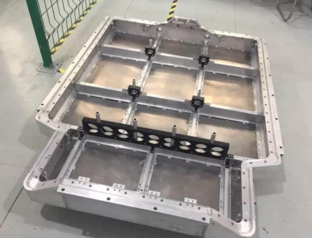
Every EV maker and energy storage plant fights the same headache with aluminum battery trays. These huge, thin-walled structural parts need perfect flatness, leak-proof sealing grooves, precise module mounting holes, and zero thermal warping after machining. Standard 3-axis mills churn out scrap batches, waste tooling, and blow delivery deadlines.
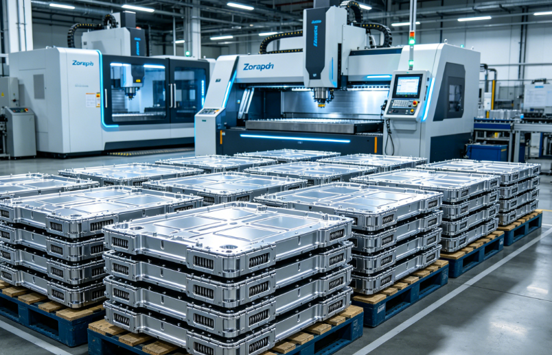
At Zorapid, we run dedicated large-format 5-axis gantry CNC cells exclusively for new energy aluminum trays. We’ve solved every common production pain point: thin rib chatter, aluminum built-up edge (BUE), uneven flatness, sealing surface burrs, and post-process dimensional shift. This shop-ready guide skips heavy textbook metallurgy.
We cover alloy selection, anti-distortion fixturing, PCD vs carbide tool rules, standardized high-speed milling parameters, full end-to-end CNC workflow, DFM design fixes, and a real OEM case study cutting scrap by 78%. Every process is validated on our 3,000㎡ precision production line for passenger EV, commercial truck, and grid storage battery trays.
Why Aluminum Battery Trays Break Standard CNC Machining Workflows
Before jumping into cutting parameters, let’s break down the 4 unforgiving traits of large-format 6000-series aluminum trays that wreck generic machining setups:
- Massive footprint (800–2200mm) paired with ultra-thin rib walls (1.8–3mm). Even tiny clamping force bends raw extruded/cast blanks permanently.
- High thermal expansion rate for aluminum. Heat from rough milling creates hidden residual stress that warps parts hours after machining.
- Gummy 6061-T6 / 6005A material builds heavy BUE on cheap carbide cutters, ruining critical sealing surfaces.
- Multi-sided complex geometry: deep pockets, angled mounting bosses, integrated liquid cooling channels, and hundreds of precision holes needing GD&T positional tolerance ±0.15mm.
3-axis machines force repeated re-fixturing. Each re-clamp adds alignment error and doubles cycle time. 5-axis gantry CNC completes all features in one single setup, eliminating stacking tolerance failures.
Best Aluminum Alloys For New Energy Battery Trays (Shop Quick Reference)
| Alloy Grade | Hardness | Core Use Case | Machining Strength | Key Weakness To Mitigate |
|---|---|---|---|---|
| 6061-T6 | 24–28 HRC | Passenger EV trays, low-to-medium volume prototypes | Balanced strength, cheap raw stock | High thermal expansion – staged rough machining mandatory |
| 6005A-T6 | 26–30 HRC | European commercial EV, extruded profile trays | Superior extrusion stability, low distortion | Narrow process window for thin rib milling |
| 6082-T6 | 29–33 HRC | Heavy-duty truck & grid storage trays | Highest tensile strength for impact resistance | Slower HSM speeds, faster carbide tool wear |
Complete Anti-Distortion CNC Workflow (Zorapid Standard Production Route)
This 4-stage process cuts warpage scrap by over 70% compared to single-pass rough-finish shortcuts.
Step 1: Pre-Machining Stress Relief (Non-Negotiable)
All extruded/cast aluminum tray blanks hold massive forming stress.
- Heat blank to 340°F (170°C), soak 90 mins per meter length, slow furnace cool to ambient temperature.
- Remove all mill scale and uneven surface stock with a light skim pass before heavy roughing.
Step 2: Staged Rough Milling (Leave Uniform Finish Stock)
Never machine full depth in one pass – uneven cutting force bends thin ribs.
- Radial cut depth limited to 50% tool diameter; axial DOC max 2mm per pass.
- Leave uniform 0.3–0.5mm finish allowance on all sealing, mounting, and rib surfaces.
- Use trochoidal adaptive clearing toolpaths to lower cutting force and heat buildup.
Step 3: Secondary Stress Relief After Roughing
Rough milling locks new cutting stress into thin tray walls.
- Run low-temperature stress relief at 280°F (138°C), soak 60 mins, natural air cool fully before finishing. This single step eliminates 80% of post-finish dimensional drift.
Step 4: Single-Setup 5-Axis Semi-Finish + Super-Finish
Split finishing into two light passes for flawless sealing surfaces:
- Semi-finish pass removes 70% of leftover allowance, clears rough machining tool marks.
- Micro super-finish pass with low feed, high spindle RPM to hit Ra ≤1.6μm for IP67 gasket sealing.
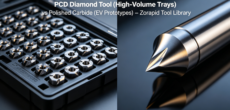
PCD vs Solid Carbide For High-Volume Tray Production
Generic 2/3 flute carbide end mills fail fast on large aluminum tray batches. Match your tool to production volume for maximum ROI:
1. Solid Polished Carbide (Prototypes & Low Volume <500 units)
- Geometry: 3-flute high helix (38°–45°), polished rake face, ZrN low-friction coating
- Rule: No TiAlN coatings – they trigger instant aluminum BUE
- Ideal for short prototype runs with frequent design changes
2. PCD Polycrystalline Diamond Tools (Medium/High Volume >500 trays)
- 4–10x longer service life than carbide; zero material adhesion on sealing grooves
- Perfect for repeated milling of flat sealing surfaces and long rib structures
- Limitation: High upfront tool cost, only cost-effective for mass EV batch orders
Critical Tool No-Go Rules
- Avoid short, stubby cutters on deep tray pockets – tool runout creates uneven wall thickness
- Skip large corner radii roughing inserts; small radii spike cutting force and bend thin ribs
Production-Proven High-Speed Milling SFM & Feed Data (6061-T6 Benchmark)
All values calibrated for 5-axis gantry CNC, high-pressure 70 bar through-spindle coolant, tray wall thickness ≥1.8mm
| Operation | SFM Range | Feed Per Tooth (ipt) | Max Axial DOC | Core Control Tip |
|---|---|---|---|---|
| Rough Trochoidal Milling | 1800–2600 | 0.005–0.008 | 0.080” | Increase feed slightly to eliminate BUE |
| Semi-Finish Rib & Pocket Milling | 2200–3000 | 0.002–0.004 | 0.020” | Reduce radial cut width to avoid rib vibration |
| Super-Finish Sealing Grooves | 2600–3200 | 0.0008–0.0015 | 0.006” | Dual coolant jets targeted directly at cutting edge |
| Precision Hole Drilling (Mount Bosses) | 1500–2000 | 0.003–0.006 | Full hole depth | Through-tool coolant to flush deep hole chips |
Zorapid Quick Tuning Hack: If you see silver aluminum smearing on cutter flutes, raise feed rate 10% and boost coolant pressure – light slow passes rub material instead of shearing clean chips.
Rigid Fixturing & Vacuum Holding To Stop Tray Deflection
Large flat aluminum trays cannot rely on standard vise clamping – uneven point pressure warps thin panels. We use two proven holding systems:
- Modular Vacuum Chuck (Flat Tray Panels, Wall ≥2mm)
- Minimum 0.8bar vacuum pressure, full-area rubber anti-mar pads
- No hard metal clamps contacting sealing surfaces (prevents indentation defects)
- Custom Hardened Support Jigs (Complex Ribbed Trays, Thin Walls <2.2mm)
- Adjustable support blocks spaced every 100mm under all rib structures
- Soft aluminum clamping claws with 3–5kN uniform clamping force, no over-tightening Universal Rule: Never clamp tray edges without full underside support – overhang creates permanent bending deformation during milling.
DFM Design Rules To Cut CNC Cycle Time & Scrap (New Energy Tray Specific)
70% of tray machining cost and scrap comes from poorly optimized drawing geometry. Our engineering team runs free DFM reviews for all EV OEM clients with these non-negotiable guidelines:
- Minimum rib wall thickness: 1.8mm for 6061-T6; 2.2mm for heavy-load 6082-T6 storage trays
- All internal pocket radii ≥R3mm; tiny small radii require fragile micro tools that slow production 3x
- Separate deep cooling channels from thin structural ribs to avoid cross-vibration during milling
- Loosen non-critical feature tolerances to ±0.2mm; reserve tight ±0.1–0.15mm GD&T only for sealing and mounting holes
- Add 0.5mm draft angles to deep pocket side walls for smooth chip evacuation
- Avoid blind deep holes deeper than 3× hole diameter – trapped chips leave internal micro burrs impossible to clean
Common Aluminum Battery Tray CNC Failures + Instant Fix Cheat Sheet
- Excessive tray warpage / uneven flatness over 1m length Root Cause: Skipped double stress relief, uneven vacuum clamping, single-pass heavy roughing Fix: Add pre + post rough stress relief, install full-area vacuum chuck, split roughing into shallow staged passes
- Silver BUE buildup on sealing groove cutters Root Cause: Low feed rate, unpolished carbide tools, insufficient coolant flow Fix: Raise feed 10–15%, switch polished high-helix ZrN cutters, activate dual high-pressure coolant jets
- Chatter ripples on thin vertical rib walls Root Cause: Overly deep axial DOC, weak underside support, long tool stickout Fix: Limit axial cut depth to 2mm max, add dense support blocks under ribs, shorten tool holder overhang
- Visible burrs on sealing groove edges (fails IP67 leak testing) Root Cause: Single finishing pass, low spindle RPM, dull cutting edge Fix: Two sequential super-finish light passes, bump SFM to upper range, replace inserts at first minor wear sign
- Hole positional tolerance out of spec Root Cause: Multiple re-fixturing on 3-axis machines, thermal expansion without cool-down time Fix: Migrate production to 5-axis single-setup machining, let tray cool fully before CMM inspection
- Rapid carbide tool wear during mass batch runs Root Cause: Generic uncoated cutters, excessive radial width of cut Fix: Upgrade to PCD diamond tools for high-volume orders, reduce radial WOC to max 50% tool diameter
Zorapid Real-World EV OEM Case Study – 1200mm Commercial Truck Battery Tray Overhaul
A North American electric truck OEM sent us a failing production batch of 6061-T6 battery trays with three costly manufacturing failures:
- 78% scrap rate from severe post-machining flatness warpage
- Tool replacement every 12 trays, sky-high monthly carbide tool overhead
- 112-minute single-unit cycle time, unable to hit quarterly volume targets
Original flawed workflow: Single-pass rough-finish 3-axis machining, zero pre/post stress relief, standard uncoated carbide cutters, basic edge clamping without vacuum support.
Our Zorapid full CNC process overhaul:
- Added dual-stage pre-blank + post-rough stress relief furnace cycles to lock dimensional stability
- Swapped 3-axis setup for dedicated 5-axis gantry single-setup machining, eliminated repeated re-fixturing
- Upgraded mass production tooling to PCD diamond cutters for sealing grooves and rib milling
- Installed full-surface modular vacuum chuck with dense adjustable rib support blocks
- Rewrote CAM toolpaths with trochoidal adaptive roughing + dual light super-finish passes for IP67 sealing surfaces
Measurable Final Production Results
- Warpage scrap rate dropped from 78% to 1.3%
- Tool service life extended 4.7x, monthly tooling cost cut by 79%
- Per-tray cycle time reduced from 112 mins to 68 mins, monthly output increased 65%
- 100% pass rate on IP67 water tightness and CMM GD&T positional tolerance inspection
Why Zorapid Leads New Energy Aluminum Tray CNC Manufacturing Globally
We operate a segregated large-format 5-axis gantry CNC production line built exclusively for EV and energy storage aluminum tray components, serving OEMs across North America, EU, UK and Southeast Asia. Our exclusive competitive advantages:
- 3,000㎡ precision manufacturing center with 6 heavy-duty 5-axis gantry CNC machines with through-spindle 120 bar coolant systems
- In-house heat treat furnaces for mandatory double stress relief cycles (no outsourced third-party furnace delays)
- Full dedicated PCD & polished carbide tool library calibrated for 6061-T6 / 6005A / 6082 aluminum tray alloys
- Free upfront DFM engineering reviews to eliminate distortion, burr and tolerance risks at drawing design stage
- Full post-process quality control: CMM full GD&T inspection, flatness laser scanning, IP67 water leak testing, surface roughness verification
- Flexible lead times: EV tray prototypes in 5–7 business days; medium/high-volume batch CNC machining delivered in 10–18 business days
Final Key Takeaways For Stable Low-Scrap Aluminum Battery Tray CNC Machining
- Double stress relief (pre-blank + post rough milling) is mandatory for all large-format aluminum trays – it eliminates nearly all warpage scrap.
- 5-axis single-setup machining beats repeated 3-axis re-fixturing on every metric: tighter tolerances, shorter cycle time, zero stacking alignment error.
- Match tooling to production volume: polished carbide for prototypes, PCD diamond cutters for mass EV batch runs to slash long-term tool cost.
- Vacuum full-surface holding + dense underside rib support eliminates clamping deformation that ruins flatness specs.
- Split all finishing into two light micro-passes to deliver burr-free Ra ≤1.6μm sealing surfaces critical for IP67 waterproof performance.
- Early DFM geometry adjustments reduce cycle time, tool wear and scrap rates by up to 75% on every new energy tray project.
FAQ
What aluminum alloy is best for passenger EV battery trays?
6061-T6 is the global standard for light passenger EVs; European OEMs often specify extruded 6005A-T6 for consistent extrusion stability.
Can we skip stress relief for small compact battery trays under 600mm length?
We still recommend post-rough stress relief for consistent batch flatness; thin ribbed compact trays still hold heavy cutting stress after milling.
Is PCD tooling worth the upfront cost for low-volume prototype tray orders?
No – polished ZrN coated solid carbide cutters deliver lower total cost for runs under 500 units. PCD ROI kicks in at 500+ batch volume.
What flatness tolerance can Zorapid hold on 2m long aluminum battery trays?
Consistent flatness ≤0.1mm over full 2-meter tray surface, fully compliant with global EV OEM GD&T standards.
Do you offer full post-CNC surface finishing for battery trays?
Yes – in-house anodizing, chromate conversion coating and ultrasonic degreasing for corrosion resistance before battery pack assembly.