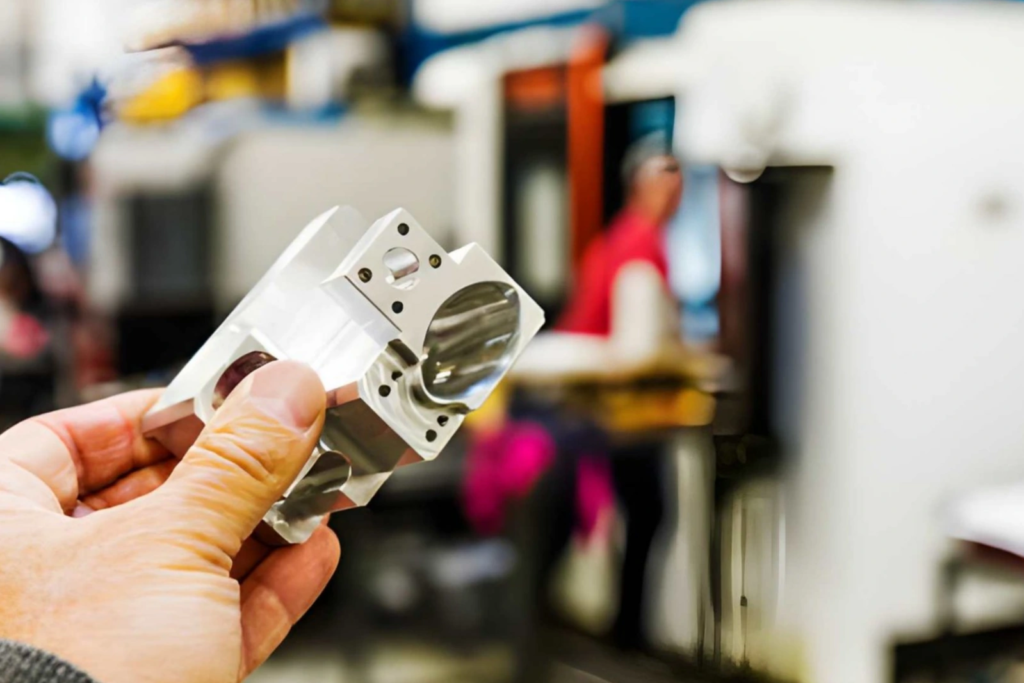
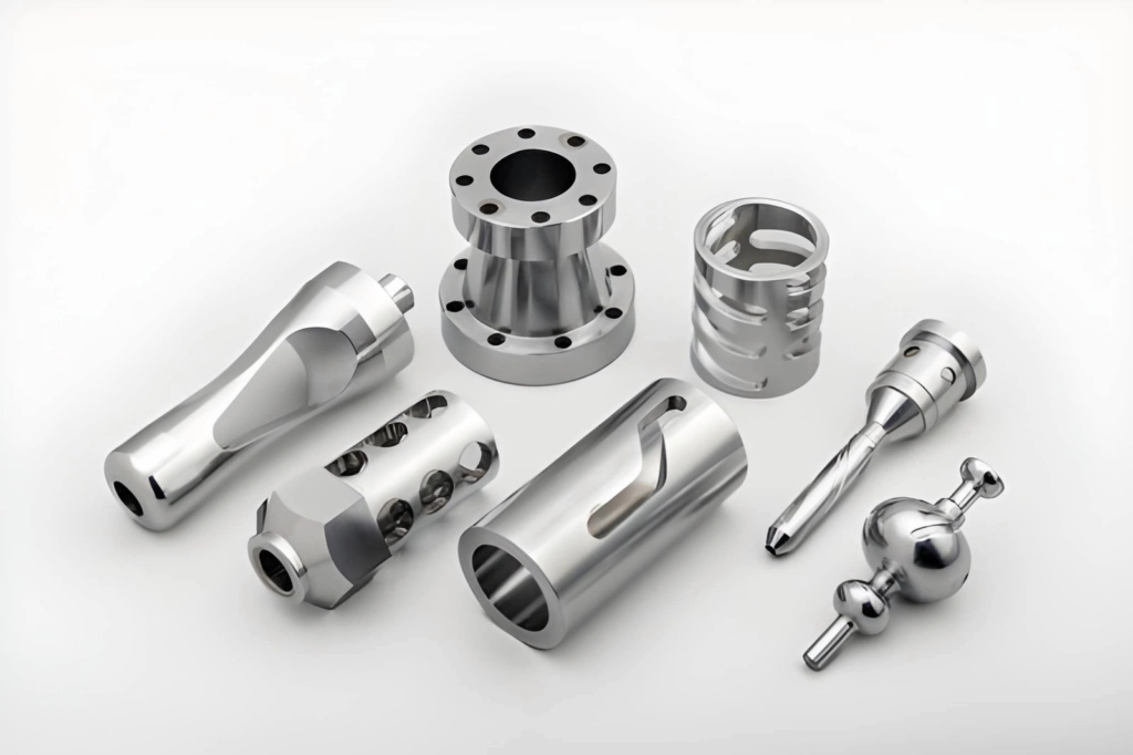
Complex CNC Machined Parts
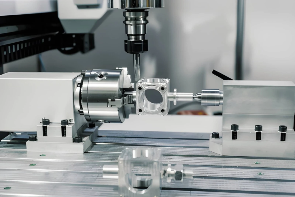
Such parts feature multi-axis machining characteristics, deep cavities, thin-wall sections, and tight positional tolerances. They are commonly used in aerospace housings, robotic joints, and precision enclosures. The alignment accuracy of features on these components must be maintained within ±0.01 mm to 0.02 mm. Traditional machining methods often struggle to meet these requirements, so engineers adopt indexing 4-axis machining and high-speed 4-axis machining. 5-axis machining controls complex geometries in a single setup.
In production environments, deep cavities require longer tools, which increase tool deflection and compromise dimensional control. Thin walls with a thickness of less than 2 mm are prone to displacement during finishing, especially under unbalanced material removal conditions.
Machining methods for complex parts include multi-axis machining strategies, the machining sequence of critical features, and the control of tool deflection and cutting heat.
Complex CNC Machined Parts
From a machining perspective, what factors make a part complex?
A part becomes complex when standard machining methods can no longer reliably maintain its dimensional and positional accuracy. Challenges usually arise during fixturing, cutting, or machining hard-to-reach features.
Setup Dependency and Data Control
Most complexity arises from parts that require multiple setups. Alignment issues occur when machining features face different orientations during production.
- Re-clamping causes part shifting, resulting in feature position deviations of 0.02 mm or more in the manufacturing workflow.
- Machined features processed under different setups will lose true positional alignment.
- Using inconsistent data across different procedures leads to assembly mismatches.
- Poor fixture contact causes the workpiece to deflect and shift under cutting loads.
Control Methods
- Place all critical features in a single setup whenever possible.
- Adopt fixed datums and repeatable locating pins throughout all operations.
Tool Usage and Cutting Limitations
Complex geometries often restrict tool feed and cutting stability. Deep grooves and angled features are particularly prone to machining issues.
- Long tools tend to deflect during cutting, increasing dimensional errors in deep cavities.
- Fine internal structures require delicate precision tools, which wear out much faster in production applications.
- Tool interference commonly occurs at intersecting or angled features.
- Confined access channels extend cycle time and degrade surface finish quality.
Control Methods
- Adopt 5-axis machining to shorten tool length and improve machining accessibility.
- Optimize internal corner radii to allow the use of larger, more rigid cutting tools.
Geometric Instability During Machining
Material removal alters the mechanical behavior of parts during cutting. Thin sections and uneven raw stock cause part deflection and deformation throughout the manufacturing workflow.
- Thin walls tend to shift during finishing, driving dimensions out of tolerance.
- Deep cavities trap chips and lead to localized temperature rise.
- Unbalanced material removal releases internal residual stress and causes part bending.
- Poor chip evacuation in enclosed structures damages surface finish quality.
Control Methods
- Reserve uniform machining allowance before processing and balance material removal volume.
- Adopt a step-by-step depth reduction strategy and apply proper chip removal methods.
How to Draw Drawings for Complex CNC Machined Parts
Engineering drawings must guide actual machining and inspection work. Missing details or unclear references will lead to setup errors and part scrapping.
Clear dimensioning and critical tolerances (fundamentals of GD&T)
Dimensions must define the relationship between all features. Tolerances should match functional requirements instead of adopting a generalized standard.
- Precision for critical hole diameters and fits shall be specified within ±0.01 to 0.02 mm where required.
- Hole positions should be controlled by positional tolerances rather than chain dimensioning.
- Datum references must be fixed and consistent across all functional features.
Identify Functional Surfaces and Critical Features
Before machining starts in the manufacturing workflow, functional areas must be clearly defined. These features govern assembly fit and part performance.
- Bearing seats and mating surfaces shall be marked as critical features.
- Surface finish requirements shall be specified for sliding or contact areas.
- Mounting surfaces shall include flatness or perpendicularity controls.
Avoid overcomplicated design.
Complex geometries increase machining time and the risk of dimensional errors. The design should ensure stable cutting and tool operation.
- Overly deep and narrow grooves should be avoided, as they cause tool deflection.
- Sharp internal corners should be replaced with tool-friendly fillets.
- To maintain machining stability, thin walls should be limited to no less than 1.5 to 2 mm in thickness.
DFM Notes for Complex CNC Machined Parts
Below are key DFM guidelines to improve machining stability and reduce production risks.
- Maintain one primary datum reference for all critical features.
- Concentrate tightly toleranced features to be machined in a single setup whenever possible.
- Adopt standard tool sizes to reduce custom tooling and shorten lead time.
- Avoid combining extremely tight tolerances with large unsupported features.
Design Tips for Complex CNC Machined Parts
The design must support stable machining and precise feature control. Key dimensions and feature relationships shall follow ASME Y14.5 GD&T principles, which ensure positional accuracy and functional alignment throughout machining and assembly.
Hole Positioning
Hole layout affects alignment, tool accessibility and structural stability.
| Keep edge distance at least 1.5 times the hole diameter to prevent edge chipping. |
| Limit depth-to-diameter ratio to approximately 5:1 for stable drilling. |
| Cross holes or angled holes usually require additional setups and reduce positioning accuracy. |
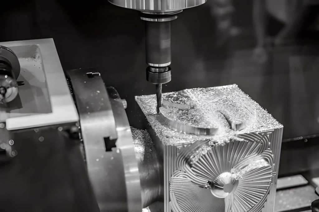
Milling Deep Features
Deep cavities increase tool deflection and heat accumulation.
- To improve tool stability, keep the depth-to-width ratio below 3:1.
- A larger fillet radius allows the use of bigger, more rigid tools.
- For grooves deeper than 20 to 30 mm, reserve sufficient space for effective chip evacuation.
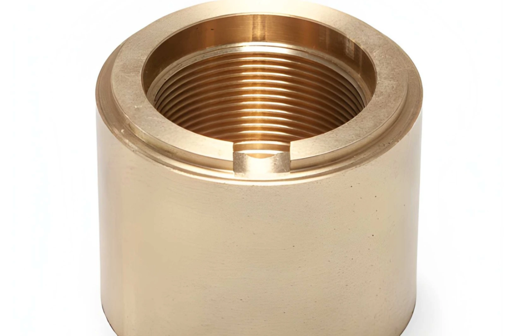
Threads and Inserts
Thread size and depth affect machining reliability and structural strength.
- Threads smaller than M3 are difficult to machine and inspect.
- A thread depth beyond 1.5 times the diameter provides no additional holding strength.
- Using threaded inserts in aluminum components improves wear resistance and allows repeated assembly.
Text & Engraving
The design of textual features shall prioritize tool accessibility and readability.
| When engraving, stroke width shall be kept at least between 0.3–0.5 mm. |
| To avoid tool overload, engraving depth shall be limited to 0.2–0.5 mm. |
| Avoid sharp internal corners on text to match tool radius. |
Part Radii
Internal radii must match available cutting tool sizes.
| Radii smaller than 0.5 mm should be avoided unless functionally necessary. |
| For stable cutting, use radii equal to or larger than the tool diameter. |
| Enlarge corner radii of deep cavities to reduce tool deflection. |
If your design includes deep pockets, small holes, or tiny internal radii, please inform the Zorapid engineering team. Share your drawings for review. Our engineering team will assess tool access and clearance before production, check if standard tool sizes can be applied, verify hole depths, and ensure overall machining feasibility.
Why is CNC machining more popular than other processing technologies for complex parts?
While maintaining high precision, material versatility and batch consistency, CNC machining can fabricate complex structures with fewer processes, making it better suited for high-end industrial scenarios than casting, 3D printing, sheet metal and other manufacturing technologies.
CNC Machining Technology for Complex Part Manufacturing
Different processing technologies are adopted according to part shapes and feature types. The production solution depends on tool accessibility, precision standards and functional requirements.
CNC Milling Machine
CNC milling is suitable for non-rotational and multi-curved parts. It can process cavities, grooves and angled features.
- Ideal for prismatic parts and complex surfaces.
- Suitable for features on multiple faces.
- Compatible with 3-axis to 5-axis machining centers.
CNC Turning
CNC turning is used for machining round and symmetrical parts. It maintains accurate alignment between diameters and bore sizes.
- Suitable for shafts, bushings and cylindrical components.
- Keeps concentric features within a single setup.
- Can be combined with milling operations on turn-mill composite machines for integrated processing.
Electrical Discharge Machining (EDM)
EDM is adopted where cutting tools cannot reach or perform conventional machining. It operates without any cutting force.
| Suitable for sharp internal corners and narrow slots |
| Applicable to hard materials |
| Ideal for deep and complex cavities in the manufacturing workflow |
When to Choose Each Technology

Complex geometries requiring multi-axis machining — Zorapid CNC machining capability supports the stable production of high-precision components.
Surface Treatment of Complex CNC Machined Parts and Its Functional Impact
When selecting a surface treatment, the intended application of the part must be taken into account.For complex CNC machined parts, coating thickness and surface dimensional changes must be planned prior to machining.Tolerances shall be defined based on the final post-coating condition.Machining allowance shall be reserved where necessary to ensure proper fit and functional performance.
Anodizing treatment enhances protection and dimensional stability.
The anodizing process is commonly applied to aluminum parts when improved wear resistance and corrosion resistance are required. It is especially widely used for housings, brackets, structural frames and other components that are frequently exposed to air or subject to minor abrasion.
- With a typical coating thickness of 5 to 25 microns, anodizing reduces hole diameter and.
- Bearing seats and mating holes need to reserve machining allowance before coating.
- The hardened surface improves wear resistance of sliding or contact areas.
- affects tight fits, especially on precision holes and mating features.
It is ideal for scenarios where components need protection without adding significant weight.
Coatings and Plating for Improved Wear and Corrosion Resistance
Coatings are required when parts operate in humid, corrosive or contact-prone environments. Depending on functional needs, coatings can be applied to both internal and external surfaces of components.
| Electroless nickel plating (10 to 30 μm) delivers uniform coverage even on complex geometries. |
| Powder coating (60 to 120 μm) is used for external parts to provide protection and surface finishing. |
| Threads and precision features shall be masked to maintain assembly fit and clearance. |
Suitable for applications requiring corrosion resistance or surface protection of parts.
Chromium Plating and Build-up on Critical Areas
Chromium plating suits parts under frequent sliding and contact loads, ideal for shafts, pins and wear surfaces.
- At a thickness of 10 to 50 µm, chromium plating increases shaft dimensions and interferes with the fit of mating components.
- Uneven material build-up often occurs on edges and corners, which affects precision-critical areas.
- The hardened surface reduces wear in high-contact zones.
For ultra-high precision fit parts like 20 mm holes and 10 mm shafts, coating impact must be accounted for before machining.
During the review process, Zorapid will evaluate the thickness of anodization or plating and apply necessary allowances to maintain dimensional accuracy after post-treatment.
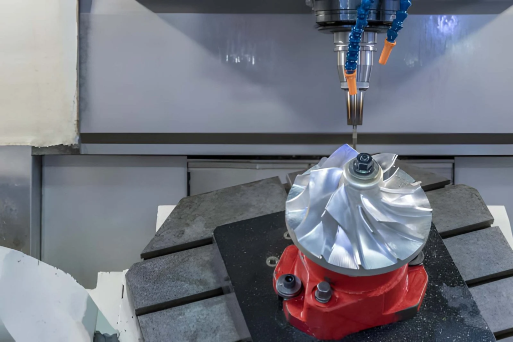
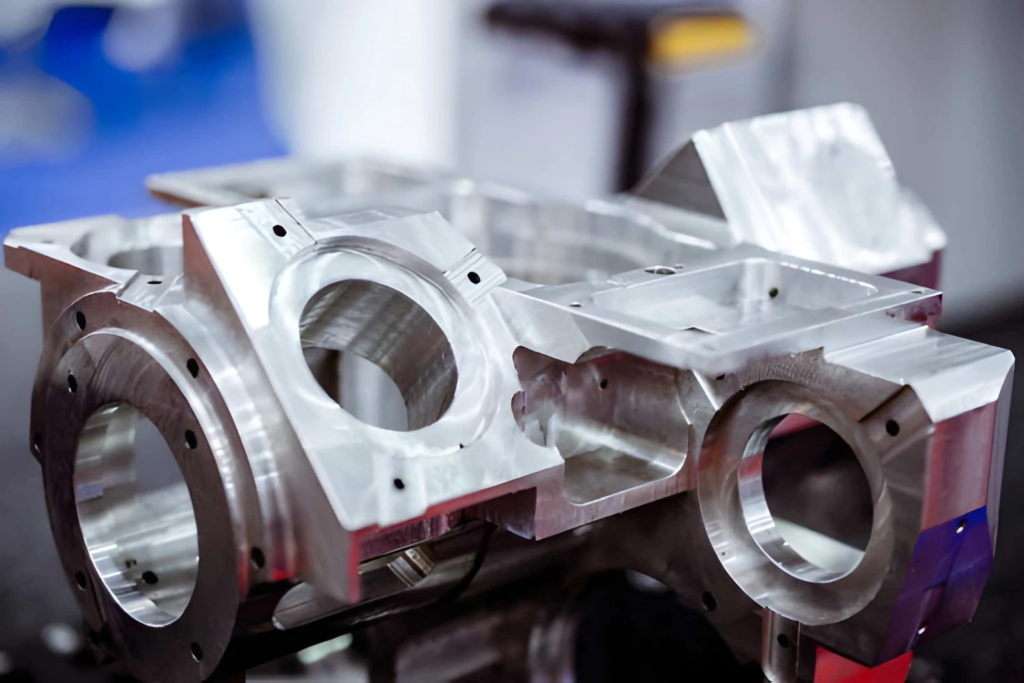
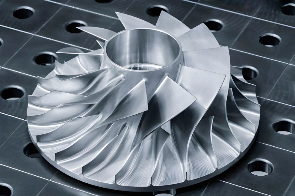
Case Study: 5-Axis Machining of Aerospace Turbine Housing
The turbine housing features angled ports, deep internal cavities, and thin walls. These characteristics require precision machining to maintain the part’s alignment and dimensional accuracy.
Initial Challenges in Geometry and Tolerance
At the initial production stage, position errors of the part at angled holes ranged from 0.05 to 0.12 mm due to multiple clamping setups. Machining deep cavities required longer tools, which caused tool deflection and compromised dimensional control. Thin-wall sections with a thickness of 1.2 to 1.8 mm also deformed during finish machining. This resulted in uneven wall thickness and misalignment during assembly.
Reducing Setup Time with 5-Axis CNC Machining
Adopting 5-axis machining cuts repeated clamping. All critical features are finished in one setup for consistent datums. Optimized tool reach lets us use shorter tools, boosting stability and reducing tool deflection.
Final Results (Tolerance, Surface Finish and Lead Time)
The table below compares the performance measurements before and after process optimization with 5-axis machining, based on actual production data.

Conclusion
Every stage of manufacturing complex CNC machined parts requires strict control, from fixturing to finish machining. Geometry, tool feed parameters, and material properties directly affect the machining accuracy of features as well as the fitting performance of parts during assembly.
Most issues in complex part machining stem from multiple re-clamping operations, excessive tool overhang, and unrealistic tolerance specifications. These commonly manifest as positional errors or surface deviations.
Thin walls, deep cavities, and long tool overhang often cause deflection and vibration during cutting. In practice, such problems can usually be identified in early Design for Manufacturability (DFM) reviews before programming begins, eliminating obvious machining risks in advance.
Zorapid — Design Guidelines & Custom Machining Solutions for Complex Parts
If your parts feature complex geometries or tight tolerance requirements, Zorapid can provide professional support starting from the design phase. Our team will review your CAD files and conduct full machining feasibility checks.
We deliver professional feedback on design optimization, tolerance rationalization, and lead time according to part complexity. We support prototype development and low-volume production with no MOQ requirements. Free DFM analysis, comprehensive pre-production review, and prototype testing are all available before formal manufacturing.
Contact us today to get a free quotation for your complex precision machining project.
FAQ
How does the typical lead time for complex CNC parts compare with simple CNC parts?
Simple parts usually take 3 to 5 days for completion. Complex parts generally require 1 to 2 weeks due to multi-axis machining, multiple setups and additional inspection procedures.
Lead time varies by material, quantity and part complexity. For urgent projects, we offer expedited production service subject to production capacity.
How to find a reliable supplier for complex CNC machined parts?
Choose a manufacturer capable of handling complex geometries and tight tolerances.
- Equipped with 4-axis and 5-axis machining capability
- Able to elaborate on setup and datum control methods
- Adopts professional inspection procedures for critical features
- Has proven experience in manufacturing similar complex components
How to reduce the cost of complex CNC machined parts?
Cost can be reduced by optimizing design for machining. Avoid deep and narrow cavities, sharp internal corners, and unnecessarily tight tolerances, as these will increase tool wear and machining time.
Concentrating critical features in a single clamping setup helps minimize positioning errors and fixturing costs. Using standard material grades and standard tool sizes also improves efficiency and lowers overall production costs.