
Publisher: Zorapid.Ltd
316L austenitic stainless steel is the most troublesome material for deep hole drilling.
It has poor thermal conductivity, severe work hardening, and forms long stringy chips that jam drill flutes instantly.
When drilling holes deeper than 5× diameter (deep hole definition), three problems constantly ruin your production:
Heat gets trapped deep inside the bore and hardens the hole wall layer by layer.
Long chips pack tightly inside flutes, recut the hole surface and snap solid carbide drills.
The drill wanders mid-depth, creating tapered bores and poor straightness.
Most shops only slow down spindle speed and add more peck retracts, but tool breakage and scrap still stay high.
At Zorapid, we drill thousands of deep blind and through holes in 316L manifolds, valve bodies and medical fluid components every month for European and North American clients.
We have built a complete set of proven solutions covering tooling, coolant, programming, parameters and fixturing to stabilize deep hole quality and triple drill life.
Today we break down every actionable solution specifically for 316L deep hole drilling, with no guesswork.
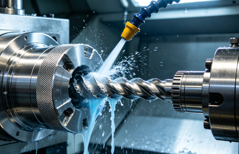
Why 316L Deep Holes Always Fail
First understand the material’s unique machining behavior in closed deep bores:
- Severe work hardening Frictional heat cannot escape from deep blind holes. Even brief dwell time hardens the bore surface up to 500HV, making further cutting almost impossible. Repeated peck-in peck-out cycles worsen thermal cycling and hardening.
- Uncontrollable long string chips 316L is highly ductile. Continuous cutting produces endless wire-like swarf. Chips get stuck in flutes, wedge between drill margin and hole wall, scratch the bore and overload torque until the drill snaps.
- Zero coolant penetration with external flood Once depth exceeds 3× diameter, the drill body blocks external coolant. No lubricant reaches the cutting tip, so edges rapidly form built-up edge (BUE) and crater wear.
- Drill deflection & hole taper Long slender drills bend under cutting thrust. The hole becomes larger at the entrance and narrower at the bottom, failing straightness and diameter tolerance.
Select the Right Specialized Drill
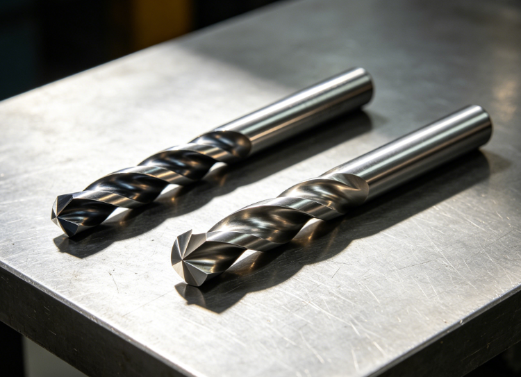
General-purpose straight-flute HSS drills never work for 316L deep holes. You must use stainless steel dedicated solid carbide drills with these strict geometries.
Drill Substrate & Coating
- Material: Ultra-fine micrograin solid carbide with medium cobalt content to resist chipping under interrupted cutting.
- Coating: AlCrN low-friction PVD coating. It prevents material welding and built-up edge far better than standard AlTiN for sticky austenitic stainless steel.
- Avoid uncoated drills: BUE will form within a few holes.
Key Geometry for Deep Hole Stability
- Point angle: 135° split point The split point eliminates center punch work hardening, reduces thrust load and prevents drill wandering. Never use the common 118° general-purpose point — it creates heavy rubbing and hardens the entry zone immediately.
- Parabolic wide flutes Large flute gullets speed up chip evacuation. Narrow standard flutes trap swarf and cause jamming in deep bores.
- Controlled back taper Minor diameter reduction along the drill body reduces contact friction between margin and hole wall, cutting heat and scratching significantly.
- Built-in chip breaker on cutting edge Breaks long continuous swarf into short C-shaped chips so they can be flushed upward easily. Without chip breakers, you will always get tangled string chips.
Tool Rule For High L/D Ratio
- 5xD ~ 12xD: Through-coolant parabolic flute solid carbide drill
- 12xD ~ 30xD: Gun drill or single-flute deep hole drill with internal coolant channels
- Always keep drill overhang as short as possible to eliminate bending deflection.
High-Pressure Through-Tool Coolant Is Non-Negotiable
External flood coolant only wets the hole opening. It cannot reach the cutting zone in deep blind holes. This is the single biggest mistake most workshops make.
Standard Coolant Setup For 316L Deep Drilling
- Use only through-coolant drills with internal coolant holes.
- Maintain coolant pressure at 70~90 bar for holes deeper than 5× diameter. The high-pressure fluid pushes chips upward along flutes continuously.
- Select stainless steel semi-synthetic coolant with excellent anti-weld and anti-BUE additives. Straight oil will cause too much smoke and thermal buildup.
- Keep the nozzle flow balanced so chips never fall back into the hole after retraction.
Measurable improvement:
With external flood only: drill life = 15~20 holes
With 75 bar through-tool coolant: drill life jumps to 60~80 holes, no more chip recutting.
Optimized Peck Drilling Cycle
Frequent long retracts create repeated heating and cooling, accelerating surface hardening on 316L. We split the drilling cycle into two strict modes based on coolant conditions.
Mode A: With High-Pressure Through Coolant
Run continuous single-stroke drilling with minimal retracts.
No frequent pecking. Keep the drill cutting steadily without pulling out fully.
This eliminates thermal cycling and stops work hardening from repeated entry and exit.
Only retract fully once every 15~20mm of depth for full chip clearing.
Mode B: No Through Coolant
You have to use short-stroke high-frequency pecking:
- First peck depth = 0.5× drill diameter (shallow entry to stabilize position)
- All subsequent pecks = only 0.2~0.3× diameter
- Retract fully out of the hole on every peck to let coolant flush all chips out completely
- Never let the drill dwell at the bottom of the hole. Dwell instantly hardens 316L stainless steel.
Tuned Feeds & Speeds To Avoid Rubbing & BUE
316L cannot stand slow rubbing cutting. Slow RPM causes edge welding and built-up edge. We use steady moderate spindle speed with stable chip load.
Recommended Parameters
- Cutting Speed (SFM): 220 ~ 320
- Feed Rate: 0.08 ~ 0.14 mm/rev (maintain consistent chip load, do not slow feed randomly)
- Depth per peck: Follow the peck cycle rules above
- Reduce spindle speed by 20% once depth exceeds 10× diameter to lower torque and deflection.
Key principle: Keep the tool shearing material, not rubbing it. Rubbing creates heat, hardening and edge welding.
Rigid Fixturing & Pre-Drilling Steps To Prevent Hole Deviation
Drill wandering creates tapered deep holes and out-of-tolerance straightness. Follow these setup rules:
- Machine a shallow pilot hole first with a short rigid center drill (depth 1.5× diameter). The pilot hole locks drill position and prevents tip deflection at entry.
- Clamp the workpiece on a full solid base plate without overhang. Thin plate vibration bends the drill bit mid-cut.
- Use high-precision hydraulic collet chucks, not standard ER collets. Minor chuck runout amplifies wobble in deep holes. Keep total runout below 0.003mm at the drill tip.
- Clamp the part tightly to eliminate workpiece vibration that amplifies drill bending.
For cross-hole deep drilling on manifolds, add support behind the exit side to prevent breakout burrs and hole deformation when the drill breaks through.
Eliminate 6 Common Deep Hole Defects
| Defect | Root Cause | Immediate Correction |
|---|---|---|
| Long string chips jamming flutes | No chip breaker + low feed | Switch to parabolic flute drill with chip breaker; raise feed slightly to break swarf |
| Hole wall hardens, drill dulls quickly | Repeated pecking + poor coolant penetration | Upgrade to through-tool high-pressure coolant; reduce peck retracts |
| Built-up edge on drill tip | Low-friction coating missing + rubbing cuts | Install AlCrN coated carbide drills; maintain steady feed without dwelling |
| Hole tapers, big at top small at bottom | Long drill overhang + chuck runout | Shorten tool projection; use hydraulic low-runout chuck; add pilot hole |
| Drill snaps off mid-depth | Packed chips overload torque | Shorten peck stroke; flush chips fully with high-pressure internal coolant |
| Scratches all over bore surface | Chips fall back and recut the wall | Keep coolant flowing upward continuously; avoid long idle retracts |
Zorapid Full Standard Deep Hole Drilling SOP for 316L
Copy this workflow for consistent high L/D deep holes with IT8 diameter tolerance and smooth surface finish:
- Prepare blank: Stress-relieve 316L plate to minimize material movement during cutting.
- Drill short rigid pilot hole to lock position and prevent wandering.
- Mount AlCrN coated parabolic flute through-coolant carbide drill in low-runout hydraulic chuck, keep overhang minimal.
- Turn on 70~90 bar internal through-tool coolant with stainless steel machining fluid.
- Program continuous single-stroke drilling with only occasional full retracts for chip clearing (no frequent short pecks).
- Run SFM 220~320 with steady feed 0.08~0.14 mm/rev, no dwell at hole bottom.
- Finish the deep bore; add a light reaming pass if tight surface roughness is required.
- Blow out chips fully before retracting the drill completely.
Measurable Production Result:
Old flood + HSS drill process: 32% drill breakage rate, rough scratched bore, frequent dimensional taper
Optimized through-coolant carbide process: Tool life tripled, hole straightness controlled within 0.006mm, Ra ≤ 0.8μm consistent bore surface, scrap rate below 1.5%
Real EU Client Case Study
A Dutch fluid power OEM ordered 316L stainless manifold blocks with blind deep holes at L/D = 14:1.
Their original drilling process had two critical failures:
- Long string chips packed tightly inside drill flutes, breaking 40% of carbide drills mid-batch
- Poor coolant penetration caused severe work hardening, leaving deep scratches on the bore wall and failing pressure testing
We revised the full process strictly following our deep hole solutions:
- Switched to AlCrN coated parabolic flute through-coolant carbide drills with built-in chip breakers
- Upgraded machine to 75 bar high-pressure through-tool coolant delivery
- Rewrote the CNC program to continuous single-stroke cutting with only periodic chip-clearing retracts (eliminated frequent peck cycles that worsened hardening)
- Added short pilot holes and low-runout hydraulic chucks to stop drill wandering and taper
Final outcome:
Zero drill breakage across the full batch. The deep bore remained straight with consistent diameter. Smooth scratch-free holes passed 350bar hydraulic leak testing without secondary honing. Total machining cost dropped by 36% from lower tool consumption and reduced rework.
Conclusion
Deep hole drilling in 316L stainless steel is not just a matter of slowing down spindle speed.
All quality problems come from four core issues: work hardening, chip jamming, insufficient tip cooling and drill deflection.
The complete set of solutions follows six clear steps:
- Use AlCrN coated parabolic flute split-point carbide drills with chip breakers
- Upgrade to high-pressure through-tool internal coolant (external flood is never enough for deep holes)
- Minimize peck retracts to avoid thermal cycling and surface hardening
- Maintain stable feed and cutting speed to prevent rubbing and built-up edge
- Add pilot holes and rigid low-runout fixturing to keep the bore straight
- Break long string chips into short segments for smooth upward evacuation
Once you fix tooling and coolant first, most drill breakage and bore defects disappear immediately.
At Zorapid, we specialize in deep hole drilling for 316L, duplex stainless and medical grade stainless fluid components across Europe and North America.
If you keep fighting chip packing, work hardening, broken drills and tapered deep bores, send your hole depth, diameter and L/D ratio. Our CNC process team will deliver the full drill specification, coolant setup and optimized CNC peck cycle program for your next batch.
FAQ
Can I skip through-tool coolant and still drill deep 316L holes?
You can only do it with short high-frequency pecking, but tool life will be very short and work hardening remains severe. For holes deeper than 5xD, through-coolant is the only reliable long-term solution to flush chips and cool the cutting tip.
Why does frequent pecking make 316L hardening worse?
Every time you pull the drill out and re-enter, the cutting zone repeatedly heats up then cools down. This thermal cycling hardens the stainless steel layer continuously. Continuous single-stroke cutting keeps temperature stable and minimizes hardening.
Is a 135° split point really necessary instead of a standard 118° drill point?
Yes. The 118° chisel edge creates heavy thrust pressure and rubbing friction on entry. The split point cuts with far less thrust load, so less heat is generated at the hole opening to prevent early work hardening.
How to handle long string chips on 316L even with good flutes?
Add edge chip breakers on the drill tip, and keep feed rate high enough to shear short C-shaped chips. Too slow a feed creates continuous wire swarf no matter how big the flute gullets are.


