
Published:Zorapid.Ltd
If you design semiconductor process equipment—etchers, PVD/CVD deposition tools, ion implanters, EUV lithography load locks—you already know one non-negotiable rule: your vacuum chamber’s precision directly controls wafer yield.
A single 5-micron error on a sealing flange, rough Ra surface, or misaligned gas port will create hidden micro leaks, trap process contaminants, or break ultra-high vacuum (UHV) stability at 10-9 mbar. Standard general CNC can’t hit the bar. Only micro ultra-tight tolerance multi-axis CNC delivers the geometry, flatness, and surface quality semiconductor vacuum systems demand.
This blog breaks down every actionable CNC rule, tolerance spec, material pick, and cleanroom process for vacuum chambers. We’ll cover micron-level machining for CF knife-edge flanges, internal gas manifolds, wafer chuck mounting lands, and full monolithic chamber bodies—plus a complete FAQ answering every pain point semiconductor OEMs bring to precision manufacturers.
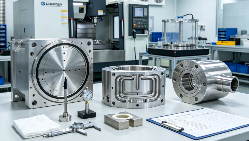
What Makes Semiconductor Vacuum Chambers So Hard to Machine
Regular mechanical housings tolerate ±0.05mm loose tolerances; semiconductor vacuum chambers operate on a totally different scale. These 4 unique challenges force micro ultra-tight CNC workflows:
- UHV zero-leak requirement Even micro-traps on sealing surfaces or threaded holes cause virtual leaks that take days to pump down, ruining wafer batch consistency. Helium leak rates must hit ≤1×10⁻¹³ Pa·m³/s for advanced process tools.
- Low-outgassing, particle-free rules Every tool mark, burr, or residual machining oil releases organics under vacuum, contaminating nanoscale wafer circuits. Machining must eliminate micro-debris entirely.
- Thermal cycling dimensional stability Chambers swing from cryogenic cold to 200°C+ bake temperatures. Uncontrolled machining stress warps flat sealing planes over thermal cycles, breaking gaskets.
- Complex monolithic internal geometry Integrated showerhead ports, cooling micro-channels, nested sealing grooves, and multi-sided CF flanges require single-setup 5-axis machining to avoid alignment drift across multiple fixtures.
Core Micro Ultra-Tight Tolerance Standards for Vacuum Chamber CNC
These are the non-negotiable micron specs for critical vacuum chamber features—all delivered via temperature-controlled precision CNC:
Dimensional Tolerances
- Sealing flange hole patterns: ±2 μm (0.002mm)
- CF knife-edge profile depth: ±1 μm
- O-ring sealing groove width/depth: ±3 μm
- Wafer chuck mounting datum features: ±0.003mm
- Non-critical outer housing features: ±0.02mm (cost-saving relaxed tolerance)
Geometric Form & Orientation Tolerances
- Sealing surface flatness: ≤0.005mm across 500mm large flanges
- Parallelism between chamber reference planes: ≤2 μm/m
- Perpendicularity of all port flanges: ≤0.002mm per 100mm
- Concentricity of rotary feedthrough bores: ≤0.001mm
- Straightness of internal gas distribution channels: ≤1 μm/100mm
Surface Roughness (Vacuum-Critical Zones)
- UHV sealing knife-edges & mating faces: Ra ≤0.1 μm
- Internal chamber plasma contact surfaces: Ra 0.2–0.4 μm
- Non-vacuum external housing walls: Ra ≤1.6 μm
5-Axis CNC Machining Rules for UHV Semiconductor Chambers
3-axis CNC requires repeated re-fixturing, introducing alignment drift. Micro ultra-tight vacuum chamber builds rely fully on rigid 5-axis precision machining. Follow these manufacturing rules:
Rule 1: Split machining into 3 stress-controlled stages
- Rough machining: Remove bulk material with low clamping force, then full stress relief bake to eliminate billet warpage
- Semi-finish: Leave 0.01–0.02mm uniform stock for final micron finishing
- Ultra-fine finish: Final pass in temperature-stabilized 20°C CNC cleanroom; no secondary re-clamping for sealing surfaces
Rule 2: Single-setup 5-axis for all critical mating interfaces
Machine CF flanges, gas ports, mounting datums, and internal manifolds in one fixture. Multiple setups add cumulative alignment errors that break vacuum seal uniformity.
Rule 3: Specialized polished carbide tooling for micro knife-edges
Standard inserts leave chatter marks on Conflat knife edges. Use ultra-fine ground ball end mills and single-point turning tools to maintain sharp, burr-free sealing ridges without micro nicks.
Rule 4: Vent all blind threaded holes to eliminate virtual leaks
Blind screw holes trap air that slowly bleeds into vacuum. CNC mill tiny vent slots down thread bores per UHV design standards.
Rule 5: Deep micro-channel machining with through-spindle coolant
Internal cooling and gas showerhead channels often hit 10:1 depth-to-diameter ratios. High-pressure coolant prevents built-up edge that leaves surface micro-defects.
Rule 6: All internal corners full radius fillets (no sharp edges)
Sharp internal corners create stress risers and particle traps. R ≥1mm minimum on all pocket and channel intersections for vacuum cleanliness.
Critical Surface Finish & Cleanroom Machining Protocols
Tight tolerances mean nothing if parts leave CNC with residual contaminants. Semiconductor vacuum chambers follow strict clean-as-you-go workflows:
- In-house Class 1000 (ISO 6) cleanroom finishing cell All final ultra-fine milling, deburring, and inspection happens inside controlled low-particle space to avoid workshop dust adhesion.
- Chemical-free precision deburring only Mechanical micro-brush flow finishing, ultrasonic vapor honing—no abrasive blasting that embeds media particles into sealing surfaces.
- Multi-stage semiconductor-grade cleaning sequence Ultrasonic degrease → high-purity IPA rinse → DI water final wash → low-temp vacuum bake to remove machining organics (cuts outgassing rates drastically).
- Electropolish passivation for stainless steel chambers Electropolishing smooths micro surface valleys, reduces gas adsorption, and improves long-term plasma corrosion resistance for etch process chambers.
- Hermetic cleanroom packaging post-inspection Finished chambers sealed in nitrogen-purged foil bags immediately after CMM testing to prevent atmospheric contamination before assembly.
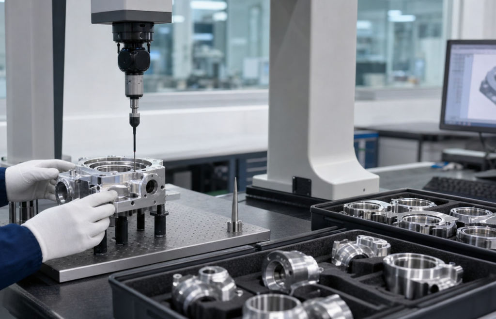
Best Low-Outgassing Materials for CNC Vacuum Chambers
Material choice directly impacts vacuum performance and CNC tolerance stability. We split grades by semiconductor application:
Aluminum Alloys (Lightweight PVD/Load Lock Chambers)
- 6061-T6: Standard lightweight chamber bodies, Type III hard anodize for plasma resistance
- 7075-T73: High-rigidity monolithic chambers, fully stress-relieved before ultra-precision finishing Advantage: Fast CNC machining, low weight, excellent thermal conductivity; avoid for heavy fluorine plasma processes.
Stainless Steel (UHV Etch / Ion Implant Chambers)
- 316L VIM-VAR Stainless: Low carbon, molybdenum alloy, resists chlorine/fluorine plasma corrosion; industry standard for high-end process chambers
- 304L: Budget general lab vacuum, not recommended for aggressive semiconductor plasma chemistries Advantage: Near-zero outgassing, ultra-low gas permeability, stable at high bake temperatures.
Specialty CNC Vacuum Materials
- OFHC Copper: Thermal cooling inserts, high-conductivity feedthroughs
- Titanium TC4: Corrosion-resistant small port inserts for harsh plasma
- Medical-grade PEEK: Insulating internal vacuum fixtures, zero metal contamination risk
Common CNC Machining Mistakes That Ruin Vacuum Integrity
These are the top costly precision errors we spot on client prototype chambers:
- Skipping stress relief between rough and finish milling → sealing surfaces warp after thermal bake
- Standard 3-axis multi-fixture machining → bolt hole pattern tolerance drifts over multiple setups
- Blind unvented threaded holes → permanent virtual leaks that never hit target UHV pressure
- Ignoring micro burrs on CF knife edges → copper gaskets fail helium leak testing
- Rough Ra >0.4 μm on mating flanges → trapped air pockets under gaskets
- Uneven wall thickness in monolithic chambers → thermal cycling creates uneven flatness distortion
- Using general workshop coolant with sulfur additives → high outgassing under vacuum bake
Real Semiconductor Chamber CNC Case Study
Project Background
Tier 1 semiconductor OEM required a monolithic aluminum load lock vacuum chamber for 300mm wafer lithography equipment.
- Target specs: Flatness ≤0.004mm on 420mm CF sealing flange, overall leak rate <1×10⁻¹² Pa·m³/s
- Initial issue: Standard 3-axis CNC prototype hit only ±0.03mm hole tolerance, failed helium leak test
Micro Ultra-Tight CNC Solution
- Full billet stress relief bake pre-machining
- Single-setup 5-axis ultra-precision CNC in temperature-controlled cleanroom
- Multi-stage fine finishing with polished carbide tooling for knife-edge flanges
- Electropolish + semiconductor multi-stage cleaning + vacuum bake outgassing treatment
Final Result
- All critical features held ±2–3 μm dimensional tolerance
- Sealing surface flatness 0.0032mm, Ra 0.08 μm
- Passed full helium leak testing, reached target UHV pressure in 18 minutes
- Stable performance through 1,000+ thermal bake cycles without seal degradation
FAQ
What’s the tightest micron tolerance your CNC can hold for vacuum chamber sealing surfaces?
We consistently deliver ±1 μm (0.001mm) on CF knife-edge profiles and ±2 μm hole pattern positioning for large UHV flanges, supported by 20°C thermally stabilized machining environments and CMM volumetric inspection accurate to 1.5μm + L/350. Flatness on sealing planes controls below 0.005mm across 500mm chamber flanges.
Why can’t standard 3-axis CNC hit semiconductor vacuum chamber precision specs?
3-axis machines require repeated re-fixturing to machine multi-sided ports and flanges. Every new setup adds alignment drift, pushing tolerances above the 5μm threshold needed for leak-free UHV. 5-axis single-setup machining eliminates cumulative position error for all critical mating surfaces.
What surface roughness do I need for Conflat knife-edge flanges?
UHV-grade CF knife edges require Ra ≤0.1 μm. Any higher roughness creates micro-valleys that prevent full copper gasket contact, leading to permanent micro leaks. We use dedicated finishing inserts to eliminate tool chatter marks on sealing ridges.
How do you eliminate virtual leaks from CNC machined threaded holes?
All blind vacuum-side threads get CNC-machined vent slots running the full thread depth. The slot lets trapped air pump out completely during chamber evacuation, eliminating slow bleed virtual leaks that ruin process pressure stability. Through holes do not require venting.
Which material is better for etch chamber CNC machining: 6061 aluminum or 316L stainless steel?
316L VIM-VAR stainless steel is mandatory for etch chambers with fluorine/chlorine plasma chemistries—it resists pitting corrosion and has ultra-low outgassing. 6061 aluminum works perfectly for load lock, transfer, and PVD chambers with mild process gases, offering lighter weight and faster CNC turnaround.
Can micro tight tolerance CNC handle integrated internal cooling micro-channels in monolithic chambers?
Yes. Our 5-axis CNC runs deep hole drilling and adaptive milling for high-aspect-ratio cooling channels, holding channel width tolerances ±3μm and smooth Ra <0.3μm internal surfaces to avoid particle buildup inside the vacuum body.
What inspection documentation comes with finished CNC vacuum chambers?
Full batch traceability material COAs, complete CMM dimensional reports for all critical tolerance features, surface roughness profilometer logs, and helium leak test certification with leak rate measurements. All records follow semiconductor OEM quality audit standards.
Do you provide cleanroom CNC machining for semiconductor vacuum parts?
Our precision division operates Class 1000 (ISO 6) cleanroom CNC cells dedicated exclusively to vacuum and semiconductor components. Final finishing, deburring, cleaning, and packaging all happen inside particle-controlled space to prevent workshop contamination.
How long does a micro ultra-tight tolerance CNC vacuum chamber prototype take?
Standard prototype lead time 7–12 business days, including stress relief machining, cleanroom finishing, multi-stage cleaning, leak testing, and full inspection reporting. Low-volume production batches (10–50 units) run 15–25 days based on chamber size and complexity.
Can your engineering team review vacuum chamber CAD for DFM precision optimization?
Free pre-machining DFM reviews for all semiconductor OEM clients. We flag design risks like unvented blind holes, sharp internal corners, over-toleranced non-critical features, and stress-prone thin walls, then propose geometry tweaks to cut machining cost while maintaining UHV performance specs.
Quick DFM Checklist for Your Vacuum Chamber CAD
Tolerance Checklist
All CF sealing flanges assigned flatness ≤0.005mm, Ra ≤0.1μm
Vacuum-side blind threaded holes include vent slots
Knife-edge profile depth tolerance locked to ±1–3μm
Non-critical external features relaxed to ±0.02mm to reduce cost
All port flange perpendicularity defined ≤0.002mm/100mm
CNC Machining Design Checklist
All internal pocket/channel corners full R ≥1mm fillets
Wall thickness balanced symmetrically to minimize thermal warpage
Integrated cooling/gas channels designed for single-setup 5-axis access
No sharp knife-edge corners that risk micro burr formation
Separate datums defined for all critical sealing mating surfaces
Material & Cleanliness Checklist
Plasma etch chambers specified 316L VIM-VAR stainless steel
Load lock/transfer chambers use stress-relieved 6061/7075 aluminum
All vacuum-facing surfaces marked for electropolish / ultra-fine finishing
Drawing notes include low-outgassing semiconductor cleaning requirements
Closing Wrap-Up
Semiconductor vacuum chamber performance lives or dies on micro ultra-tight CNC precision. Loose tolerances, rough sealing surfaces, or unmanaged machining stress create hidden leaks, particle contamination, and unstable wafer processing—costing fabs thousands in scrapped chips and unplanned downtime.
Temperature-controlled 5-axis precision CNC, cleanroom finishing, low-outgassing material selection, and UHV-specific DFM rules combine to deliver chambers that hold stable 10-9 mbar ultra-high vacuum for advanced etch, deposition, and lithography tools.
If you have STEP CAD files for custom vacuum chambers, send them over for a free DFM precision review and formal quotation. Our semiconductor CNC engineering team will optimize tolerances, flag leak-risk design flaws, and deliver a fully certified prototype timeline tailored to your equipment NPI schedule.


