
Published:Zorapid.Ltd
Core Metal AM Processes & Fundamental Limitations
Main Metal Additive Manufacturing (AM) Methods
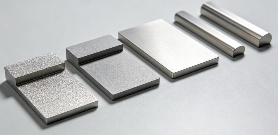
- LPBF / SLM / DMLS (Laser Powder Bed Fusion): Direct metal laser sintering / selective laser melting (most common for precision parts: Ti6Al4V, Inconel, 316L, AlSi10Mg, CoCr)
- Thin powder layers (20–60 μm), laser melting, support structures, thermal residual stress, stair-stepping effect
- EBM (Electron Beam Melting): Electron beam powder bed fusion (Ti alloys, high temp alloys), higher layer thickness (~50–100 μm), elevated build chamber temperature, coarser as-built finish
- DED (Direct Energy Deposition / WAAM / LMD): Wire/powder directed deposition (large structural parts, tooling), thick layers, low baseline precision
- Binder Jetting Metal AM: Binder jet + sintering, significant sinter shrinkage, good general geometry, poor tight tolerance as-built
- MJF / Other Indirect Metal AM: Not primary precision structural AM, higher variation
Key Baseline Truth:
- As-built metal AM cannot achieve fine precision or mirror finish directly; critical GD&T features always require post-CNC machining / EDM / finishing
- Tolerance varies dramatically by build orientation, layer height, support geometry, material, residual stress, and post-processing
- Staircase effect (layer stepping) = primary as-built surface roughness root cause; anisotropic (different X/Y vs Z-axis accuracy/roughness)
Baseline Dimensional Tolerance Specs
LPBF / SLM / DMLS (Ti6Al4V, 316L, AlSi10Mg, Inconel)
As-Built (No Post Machining)
- XY Plane (horizontal): ±0.05 mm ~ ±0.10 mm (general), fine-tuned systems: ±0.03 mm
- Z Axis (vertical build direction): worse tolerance (layer stepping, residual stress distortion): ±0.10 mm ~ ±0.20 mm
- Small features / thin walls / holes: much higher variation (minimum feature size ~0.3–0.5mm typical as-built)
- Circularity / concentricity: poor as-built; cannot meet precision journal/seal GD&T
- Holes <3mm: not for direct functional use; design for post-drilling/reaming
- General rule: ±0.1 mm per 10mm nominal dimension (as-built SLM); larger parts accumulate residual stress distortion
Post-Processed (CNC 3/5-Axis Milling, Turning, EDM, Grinding, Honing)
- Precision machined features: ±0.003 mm ~ ±0.01 mm (controlled fixturing, residual stress relief, HIP)
- Critical sealing/journals: can match conventional CNC precision with validated fixturing & stress relief
- HIP (Hot Isostatic Pressing): improves internal porosity, but can cause global dimensional shift (requires finish machining after HIP)
EBM (Electron Beam Melting)
- As-built tolerance: ±0.2 mm ~ ±0.5 mm (coarser layers, higher thermal distortion)
- Primarily for large Ti structural components, not fine precision features
DED / WAAM
- As-built tolerance: ±0.5 mm ~ ±2 mm (very rough baseline; requires heavy finish machining)
- Used for large structural frames, tooling, not micro-precision features
Binder Jet Metal AM
- As-sintered tolerance: ±0.15 mm ~ ±0.3 mm (shrinkage variation), good for non-critical geometry only
GD&T Rules
- As-built AM: avoid tight positional tolerance, concentricity, cylindricity, runout specs directly on as-built surfaces
- Assign critical CTQ datums to post-machined reference features (not as-built lattice/rough surfaces)
- Use ASME Y14.5 / ISO GD&T with separate spec for as-built vs finish-machined zones (zone GD&T)
Key Sources of Dimensional Variation
- Residual Thermal Stress: Rapid laser melting/cooling creates large anisotropic residual stress → warpage, bending, springback, dimensional drift (Ti, Inconel, Al alloys are high risk)
- Mitigate: pre-build simulation (AM simulation software), optimized support structures, baseplate heating, stress relief / HIP cycles
- Layer Stair-Stepping (Layer Height Effect): Z-axis surface error from discrete layers, especially on angled/freeform surfaces
- Mitigate: thinner layers, inclined build orientation, post-finishing
- Powder & Melting Variability: powder size distribution, laser focus variation, melt pool fluctuation, porosity, lack-of-fusion defects
- Mitigate: regular machine calibration, powder validation, process parameter DOE, SPC monitoring
- Support Removal Distortion: wire EDM/band saw support removal can introduce new residual stress
- Mitigate: controlled EDM cutting, fixture-bound finish machining, gradual support removal
- HIP/Sinter Shrinkage: densification processes cause predictable global dimensional shift
- Mitigate: pre-HIP model scaling + post-HIP finish machining
- Machine Calibration Drift: laser alignment, galvanometer drift, baseplate leveling, thermal chamber drift
- Mitigate: regular calibration, thermal control, baseline test coupons
As-Built Surface Finish Specs & Terminology
LPBF SLM As-Built Roughness (Ra, μm)
- Horizontal (XY) Surfaces (up-facing): Ra ~ 6–15 μm
- Down-Facing / Overhang / Angled Surfaces (Z / inclined): much rougher: Ra ~ 15–35 μm (staircase + support contact marks, dross, balling defects)
- Fine layer optimized SLM: Ra ~ 4–8 μm (horizontal only)
- Key defects: balling, dross, partially sintered powder adhesion, micro-cracks, surface porosity, residual trapped powder
- Lattice/inner channels: extremely rough, residual powder risk, cannot be used for fluid passage/sealing directly
EBM As-Built
- Ra ~ 25–50 μm, coarse surface texture, significant surface porosity
Post-Processing Surface Finish Results
- CNC Milling / 5-Axis Finish Machining: Ra 0.4 μm ~ 1.6 μm (general); mirror finish Ra 0.2 μm or finer with validated fine turning/milling
- Honing / Grinding / Polishing / Electropolishing: Ra 0.05–0.4 μm (sealing, medical articulating surfaces)
- Electropolish is common for Ti/CoCr medical implants (biocompatibility + smooth surface to reduce wear debris)
- Chemical / Abrasive Flow Machining (AFM) / Media Finishing: Ra 0.8–3 μm, good for internal lattices/channels (cannot achieve ultra-precise GD&T)
- Warning: media finishing alters geometry and dimensional tolerance (must be done before final CTQ finish machining)
- Coating (PVD, DLC, anodizing): add thin layer (μm scale) – mask critical datums to avoid dimensional shift
Measurement Standards
- Ra: ISO 4287 / ASME B46.1, 0.8mm cutoff filter
- 3D areal roughness (Sa) often specified for AM lattices (ISO 25178)
- Must distinguish external finish vs internal channel/lattice finish (internal cannot be easily measured with standard profilometers)
Post-Processing Tolerance & Surface Finish Modifications
Standard AM Workflow (Precision Components)
- LPBF build → stress relief → HIP densification (if required) → rough remove supports
- Finish 3/5-Axis CNC / EDM / honing on CTQ sealing/journals/datum features (maintain unified primary datum)
- Deburr, ultra-clean internal lattices (ultrasonic, chemical, AFM), validate residual powder removal
- Electropolish / PVD coating (mask critical datums), biocompatibility validation (medical)
- CMM/Form measuring machine FAI validation (AS9102/FAI)
Important HIP Note
- HIP eliminates internal porosity for fatigue-critical aerospace components but creates global dimensional distortion
- Do NOT specify final tight tolerances pre-HIP; perform finish machining after HIP
- HIP does NOT improve external surface roughness or as-built dimensional accuracy
Internal Lattice/Channel Special Rules
- As-built lattices: Ra is very high, residual powder risk, cannot apply tight tolerance specs
- Use AFM/chemical etching for internal surface improvement only, then validate flow/cleanliness (semiconductor/medical fluid paths)
- Fluid-critical AM parts: full residual powder validation (CT scan, pressure/flow testing, ultra-cleaning)
Critical DFM Rules for Tolerance & Surface Finish
- Zone GD&T Specification: split part geometry into 3 zones clearly on drawings
- Zone A: As-built non-critical geometry (loose ±0.1–0.2mm tolerance, as-built Ra)
- Zone B: Semi-finished geometry (media finish, general tolerance)
- Zone C: CTQ datum/seal/journals (post-machined, tight tolerance, specified Ra finish)
- Build Orientation DFM:
- Place critical finish-machined datums flat on XY plane, minimize steep overhangs
- Avoid deep thin vertical walls directly as-built; add sacrificial supports/geometry for post-machining removal
- Minimize 45°/angled as-built surfaces (worst stair-step roughness)
- Minimum Feature Sizing:
- As-built SLM: ≥0.4–0.5mm minimum wall thickness / hole size (avoid micro blind holes as-built)
- Finish machined: follow standard CNC DFM rules
- Support DFM:
- Place supports away from CTQ finish zones, avoid permanent dross/support marks on final surfaces
- Add sacrificial datum lugs for 5-axis fixturing (removed after validation)
- Residual Stress DFM: symmetric geometry where possible; avoid large asymmetric mass differences; add stress relief cycles
Inspection & Validation Standards
Dimensional Inspection
- CMM, optical scanner, form measuring machine, white-light interferometry, laser scanning, CT scanning (for internal lattices/porosity)
- FAI: AS9102 (aerospace), ASME Y14.5, ISO 2768
- SPC Cpk validation for CTQ post-machined features (Cpk ≥1.33 for regulated auto/aero/medical)
- Regular coupon validation: build tolerance/roughness test coupons with each batch for baseline validation
Surface Finish Inspection
- Contact profilometer (Ra), 3D optical profilometer (Sa for lattices), SEM (micro-surface integrity check)
- NDT: CT scan, ultrasonic, DPI for porosity/microcracks (fatigue-critical aero parts)
- Medical implants: biocompatibility (ISO 10993), surface roughness for articulating wear zones, no residual powder/debris
Material & Process Standards
- ASTM F3301 (Ti6Al4V AM medical), AMS 7004 (aerospace Ti AM), ISO/ASTM 52910, ISO/ASTM 52904
- IATF16949, AS9100, ISO13485 traceability & batch validation
- Powder validation: particle size, chemistry, reuse limits, MTR certification
Common Defects & Troubleshooting
- As-Built Dimensional Warpage / Distortion
- Root: residual thermal stress, insufficient supports, incorrect baseplate heating, unoptimized build orientation
- Fix: AM simulation, stress relief cycles, baseplate heating, fixture-bound finish machining, symmetric DFM
- Down-Surface Dross / Poor Roughness
- Root: overhang geometry, poor support design, incorrect laser parameters, balling defects
- Fix: re-orient geometry, add optimized supports, reduce steep overhang angles, post-media/electropolish
- Internal Residual Powder / Micro-Porosity
- Root: trapped powder, lack-of-fusion, insufficient cleaning
- Fix: validated AFM/ultrasonic cleaning, CT inspection, HIP densification (fatigue zones)
- Post-Machining Springback
- Root: unresolved bulk residual stress
- Fix: formal stress relief, staged finish passes, SPC dimensional monitoring, soak validation
- Inconsistent Ra Across Batches
- Root: powder variation, laser drift, parameter drift, media finishing variability
- Fix: fixed validated AM process recipes, batch coupons, periodic profilometer validation
Industry-Specific Spec Examples
Aerospace LPBF Ti6Al4V / Inconel (AS9100 / AMS)
- As-built non-CTQ geometry: ±0.15mm tolerance, Ra 12–25μm
- Post-machined fatigue/fluid sealing features: ±0.01mm, Ra 0.4μm or finer, full NDT porosity validation, HIP densification
- Fatigue critical: no surface microcracks, validated surface integrity, FAI/AS9102
- Lattice cooling structures: as-built Ra (specified Sa), validated flow testing, residual powder validation
Medical Ti6Al4V ELI / CoCr Implants (ISO13485 / FDA / ASTM F3301)
- Non-articulating spinal cages (lattice): as-built rough porous surface (Ra 10–25μm for osseointegration bone ingrowth, intentional roughness)
- Articulating joint bearing surfaces: electropolished finish Ra ≤0.05–0.2μm (minimize wear debris, biocompatible), ±0.01mm CTQ tolerance
- Key distinction: osseointegration lattices = intentional rough as-built surface; articulation zones = ultra-smooth post-finished surface
- Residual powder: 100% validated clean, no trapped powder, biocompatibility ISO10993 validated
Automotive AM (IATF16949, EV thermal / motor components)
- General AM cooling manifolds: as-built ±0.1mm, post-machined seal ports ±0.02mm, Ra 0.4μm for O-ring seats
- CTQ flow paths: AFM finish, leak validation, SPC Cpk monitoring, full batch traceability
- Avoid as-built direct sealing features; always finish-machine O-ring grooves
Quick Reference Cheat Sheet
Quick Spec Reference (LPBF SLM)
| Zone | Tolerance | Typical Ra | Method |
|---|---|---|---|
| As-built XY general | ±0.05–0.10 mm | Ra 6–15 μm | Direct SLM |
| As-built Z / overhang | ±0.10–0.20 mm | Ra 15–35 μm | Direct SLM |
| Post-CNC finish (general) | ±0.01 mm | Ra 0.4–1.6 μm | 5-axis CNC |
| Mirror finish seal/journals | ±0.003–0.005 mm | Ra ≤0.2 μm | Fine turning/honing/electropolish |
| Porous medical lattice (osseointegration) | Loose ±0.2mm | Ra 10–25 μm | As-built SLM (intended rough surface) |
FAQ
Can I hold ±0.02mm tolerance directly on as-built SLM metal parts?
Generally no (especially Z-axis). Only tightly calibrated fine-layer SLM can approach this on simple flat XY geometry; sustained ±0.02mm tolerance requires post-CNC finish machining.
What is the difference between Ra and Sa for AM lattices?
Ra = 2D line roughness (standard for simple surfaces). Sa = 3D areal roughness (ISO 25178), the correct spec for complex lattices/porous medical implants, to capture full 3D surface texture.
Does HIP improve dimensional tolerance and surface finish?
No. HIP removes internal porosity for fatigue performance but causes global dimensional distortion and leaves external as-built roughness unchanged. Always perform critical finish machining after HIP.
Why do medical bone ingrowth lattices specify rough as-built surface finish?
Controlled rough surface (Ra ~10–25μm) promotes bone cell attachment and osseointegration (bone ingrowth); these are intentionally not polished, distinct from articulating bearing surfaces requiring ultra-smooth finish.
How to specify AM tolerances correctly on 2D drawings?
Use zone GD&T (separate as-built vs post-machined zones), reference primary post-machined datums, add material/process spec (e.g., LPBF Ti6Al4V, AMS7004), include surface finish filter parameters (0.8mm cutoff Ra).
How to validate residual powder in AM internal lattices?
CT scanning, pressure decay testing, ultrasonic cleaning validation, flow testing, destructive cross-section inspection (batch sampling), per medical/aerospace OEM specs.
Closing Summary
Metal AM (LPBF/SLM) has anisotropic as-built tolerance and roughness limitations: reasonable horizontal XY general tolerance (±0.05–0.1mm), poor vertical/overhang as-built tolerance and surface finish, residual stress distortion risk, and internal powder/porosity risk.
- Non-critical structural/lattice geometry: specify validated as-built tolerance/roughness
- CTQ sealing, journal, snap-fit, fatigue, and regulatory features: always post 5-axis CNC/electropolish, apply formal GD&T zone specs, stress relief/HIP process validation
- Medical: differentiate osseointegration porous lattices (controlled rough Ra) vs articulation zones (ultra-smooth Ra), with full biocompatibility & residual powder validation
- Aerospace: HIP for fatigue porosity control, post-HIP finish machining, full NDT & FAI validation


