What are the processes of wire electrical discharge machining (WEDM)?
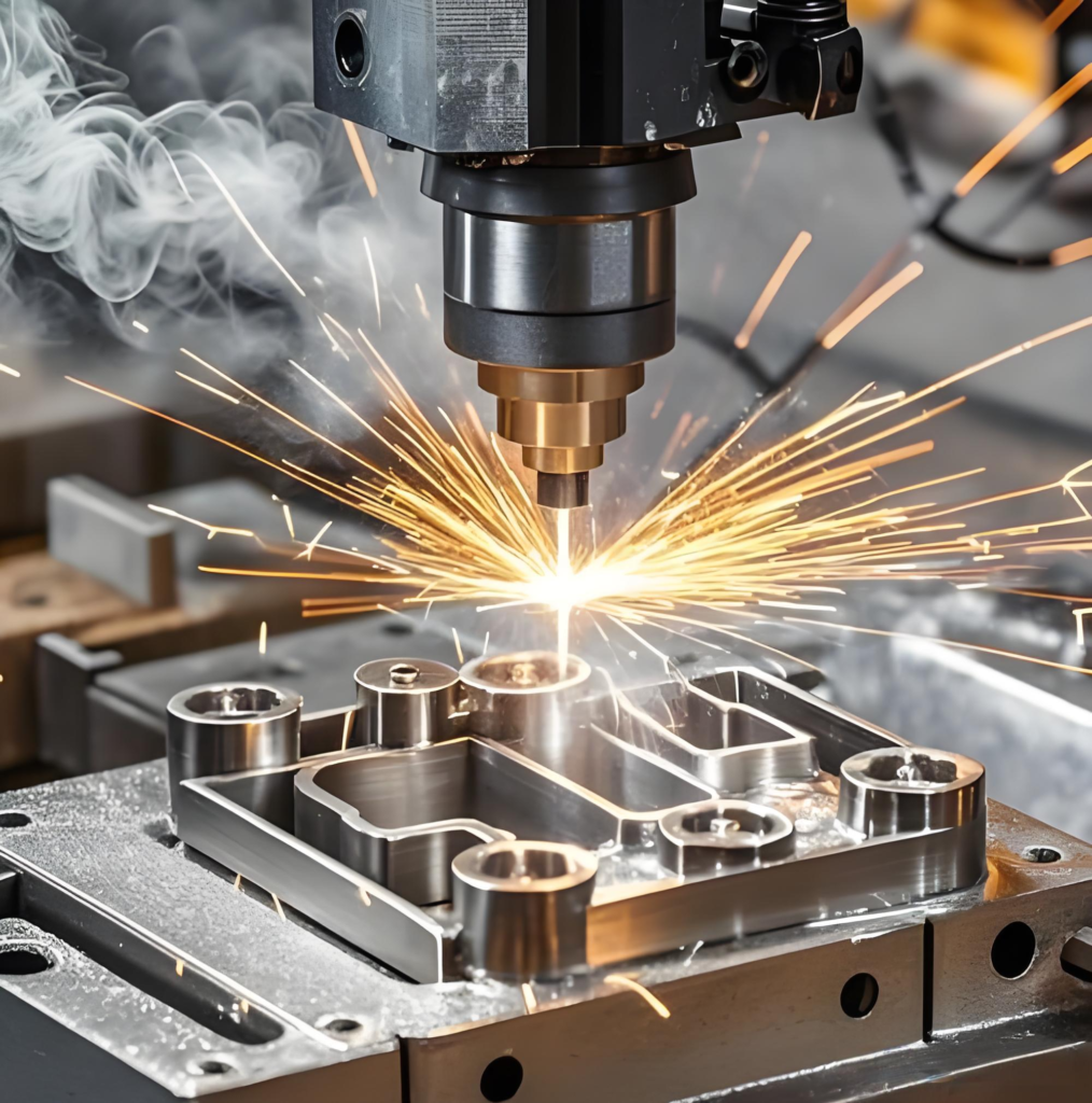
Wire Electrical Discharge Machining (WEDM), referred to as wire cutting, is a precision machining technology. It adopts pulsed spark discharge between metal electrode wires (molybdenum wire, copper wire, etc.) and workpieces to generate instantaneous high temperature, which melts or vaporizes metal materials, enabling the cutting of complex shapes. It is widely applied in mold manufacturing, aerospace, precision parts processing and other fields.
The entire process is rigorous and standardized, covering eight core procedures: drawing analysis and process planning, workpiece pretreatment, electrode wire installation and calibration, workpiece clamping and alignment, CNC programming and parameter setting, positioning and wire alignment, discharge cutting, as well as post-processing and quality inspection. Every procedure directly determines the machining accuracy and finished product quality.
Drawing Analysis and Process Planning
Before machining, thoroughly review part drawings to clarify core technical requirements including geometric dimensions, dimensional tolerances and surface roughness, and verify the applicability of wire EDM processes.
Focus on analyzing the complexity of machining contours, material properties (such as difficult-to-cut metals like hardened steel and cemented carbide), and cutting thickness. Determine the cutting path, machining allowance and fixturing solutions, including threading first for inner contours and climb cutting priority for outer profiles.
Meanwhile, avoid machining risks in deformation-prone areas such as sharp corners and narrow slits, and formulate the optimal process plan to lay a solid foundation for subsequent production.
Workpiece Pretreatment
The workpiece blank shall complete preliminary processing and cleaning in advance to meet qualified machining conditions.
Reserve uniform machining allowance in accordance with drawing requirements, and remove surface scale, burrs, oil contamination and other impurities from the blank, so as to prevent adverse impacts on discharge stability and machining accuracy.
For cutting inner contours or closed cavities, pre-machined wire start holes shall be prepared at designated positions on the blank, with the hole diameter slightly larger than the electrode wire diameter. This ensures the electrode wire can pass through the workpiece smoothly for inner contour cutting.
Finally, inspect the hardness and flatness of the workpiece to avoid deformation or cracking during machining.
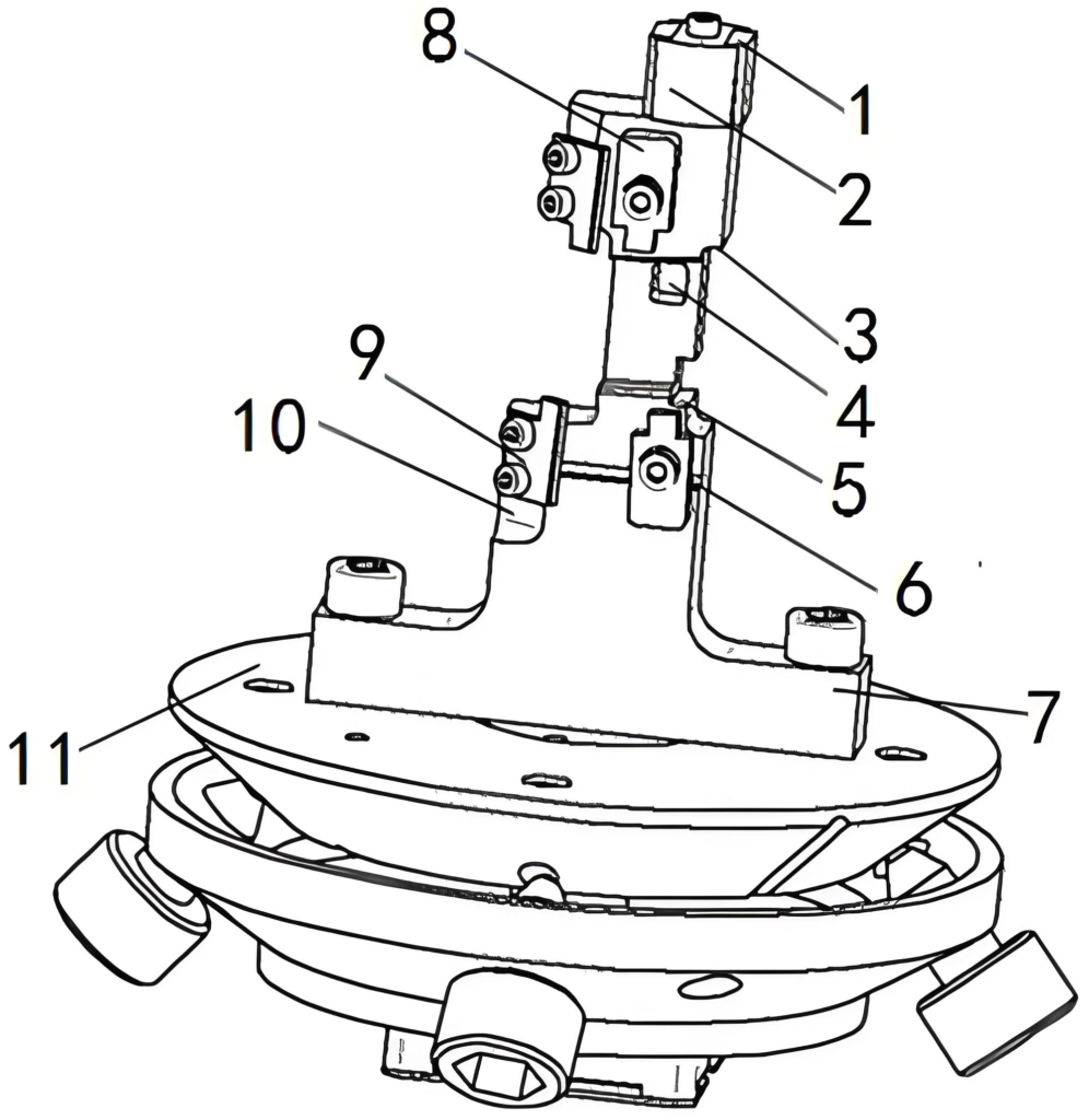
Electrode Wire Installation and Calibration
Electrode wire (molybdenum wire for high-speed wire cutting, brass wire for low-speed wire cutting) serves as the core tool for discharge cutting. Its installation and calibration directly determine kerf accuracy. Firstly, wind the electrode wire evenly on the wire drum with proper tension to prevent loose wire and wire tangling.
Proceed with wire threading afterward. For high-speed wire EDM, manually feed the electrode wire through guide wheels, frame nozzles and pre-drilled start holes of the workpiece, then fasten it to the opposite wire drum. Low-speed wire EDM supports automatic threading to ensure the electrode wire stays centered without deviation.
Finally, calibrate the verticality of the electrode wire. Use a try square or professional measuring tools to check its perpendicularity to the worktable, and adjust to uniform upper and lower gaps, so as to eliminate inclined kerfs and workpiece rejection.
Workpiece Clamping and Alignment
The workpiece shall be firmly clamped on the machine tool worktable to ensure no displacement or vibration during machining. Select suitable fixtures such as magnetic chucks, bench vices and special tooling according to the workpiece shape and size. During clamping, position the workpiece based on the reference surface to ensure uniform stress and tight fitting.
Precise alignment shall be conducted after clamping. Utilize dial indicators, micrometers and other measuring tools to calibrate the parallelism between the workpiece reference edge and the machine coordinate axis, and set the origin of the workpiece coordinate system, so that the machined contour can fully match the drawing dimensions.
Repeated verification is required in clamping and alignment, with the error controlled within 0.01mm, to prevent machining rejection caused by positioning deviation.
CNC Programming and Machining Parameter Setting
CNC programming is the core technical step of wire EDM. It converts drawing contours into machine-recognizable machining commands. For simple shapes, manual programming with 3B or ISO codes is applicable. For complex contours, CAD/CAM software such as UG and CAXA is used to create graphics and generate electrode wire motion paths. The wire offset is calculated and set based on wire diameter and discharge gap to avoid dimensional deviation of the cutting kerf.
After programming, key machining parameters are configured, including pulse width, pulse interval, machining current, wire travel speed, and working fluid flow rate.
Parameters shall be matched to workpiece material and thickness. For high-hardness materials and thick workpieces, increase pulse width and current to improve cutting efficiency. For high-precision machining, reduce relevant parameters to lower surface roughness.
Tool Setting and Positioning, Machining Start Point Confirmation
Tool setting and positioning are critical for precise cutting, aiming to define the relative position between the electrode wire and the workpiece and lock the cutting start point.
Turn on the machine’s weak machining mode, and move the worktable to slowly bring the electrode wire close to the workpiece reference edge. Record the current coordinate values once faint discharge sparks occur upon contact between the wire and the workpiece, completing reference tool setting.
For inner contour cutting, move the electrode wire to the center of the wire threading hole and set it as the machining start point. For outer contour cutting, reserve a safe clearance outside the workpiece to confirm the entry starting position. Recheck coordinate accuracy repeatedly after tool setting to ensure zero deviation of the start point and prevent contour cutting errors.
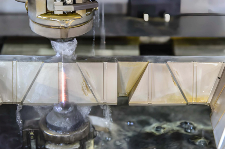
Equipment Startup & Discharge Cutting Machining
After completing all preliminary preparations, proceed to formal cutting with real-time monitoring of the entire machining process.
Turn on the machine power supply, wire feeding mechanism and working fluid circulation system in sequence. Adjust the flow of the working fluid nozzle to fully submerge the cutting area between the electrode wire and the workpiece. The working fluid functions in cooling, chip removal and insulation.
After confirming normal equipment operation, activate the CNC program. The worktable moves along the preset path driven by the machine. Continuous pulsed spark discharge is generated between the electrode wire and the workpiece to cut the target contour step by step.
Key monitoring items during processing: wire breakage, stable discharge performance (free of short circuit and overcurrent), sufficient working fluid supply and uniform kerf width. Stop the machine immediately once any abnormality occurs to avoid workpiece scrap.
Post-processing and Quality Inspection of Workpieces
After cutting, turn off the machine power, wire moving mechanism and working fluid system in sequence. Dismantle the workpiece and electrode wire, and clean residual metal debris and working fluid on the worktable and fixtures.
Subsequently, conduct workpiece post-processing: remove burrs on the cutting edge, clean oil stains and impurities on the workpiece surface, and perform polishing if necessary to improve surface roughness.
Finally, carry out comprehensive quality inspection. Use calipers and micrometers to measure dimensional accuracy, adopt roughness testers to examine surface quality, and apply coordinate measuring instruments to verify the precision of complex contours, so as to confirm whether the workpiece meets all technical requirements of the drawings.
Qualified workpieces will be put into storage, while non-conforming products will be analyzed for defects with rework solutions formulated accordingly.
The eight major processes of wire electrical discharge machining are closely interconnected. Precise control of each procedure is the key to high-precision and high-efficiency machining.
From preliminary drawing analysis to final quality inspection, strict compliance with process specifications and parameter optimization based on workpiece characteristics can maximize the advantages of wire cutting technology, and produce high-quality parts that meet stringent precision manufacturing standards.
Why choose Zorapid for wire EDM part manufacturing?
Choosing Zorapid for wire EDM component manufacturing delivers core advantages: consistent high precision, strong capability for complex and special-shaped parts, full-process controllability, fast lead times, regulatory compliance and optimized cost. It is ideal for long-term, stable delivery of high-end precision components and complex molds.
Micron-level precision manufacturing with stable and controllable accuracy
Premium equipment: Full range of mid & low-speed wire EDM, with top-tier Japanese and Swiss machines as standard. Positioning accuracy up to ±0.001mm, repeatability ±0.002mm. Stable kerf accuracy of ±0.003mm for thick workpieces up to 100mm.
Mature standardized workflows apply single cutting with multi-finishing and repeated stress relief. Mirror surface finish reaches Ra ≤ 0.05μm, cutting down post polishing significantly. We deliver one-piece forming for 0.05mm narrow grooves, R0.02mm sharp corners and complex upper/lower irregular profiles
Zero deformation guaranteed. Non-contact EDM generates no cutting force, ideal for ultra-thin walls, slim and distortion-prone parts. Pre-treated raw material plus post-cut stress relief effectively controls thermal and mechanical deformation.
Hard & Hard-to-Cut Material Expert, Pushing Machining Boundaries
Full material capability: We process high-hardness conductive materials — HRC58–62 hardened steel, carbide, tungsten, titanium and superalloys. Post-quench machining prevents thermal deformation and boosts mold lifespan.
Hardness no longer a limit. EDM material removal relies on electrical erosion, independent of hardness. We run consistent mass production on hard, brittle and thin parts beyond standard CNC capabilities.
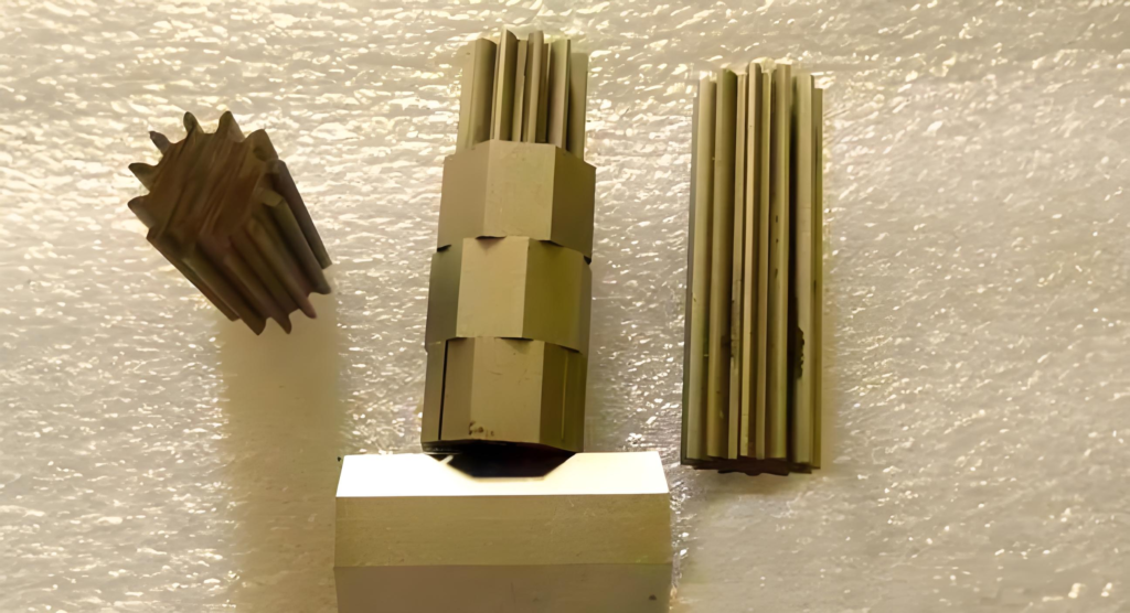
One-stop complex structure forming to solve unmachinable challenges
Custom Contour Machining
Single programming for through holes, blind holes, ±30° tapers, bevels, offset profiles and complex cavities. No custom electrodes needed, cutting lead times drastically.
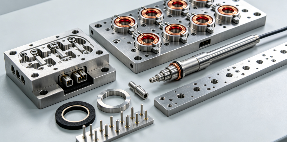
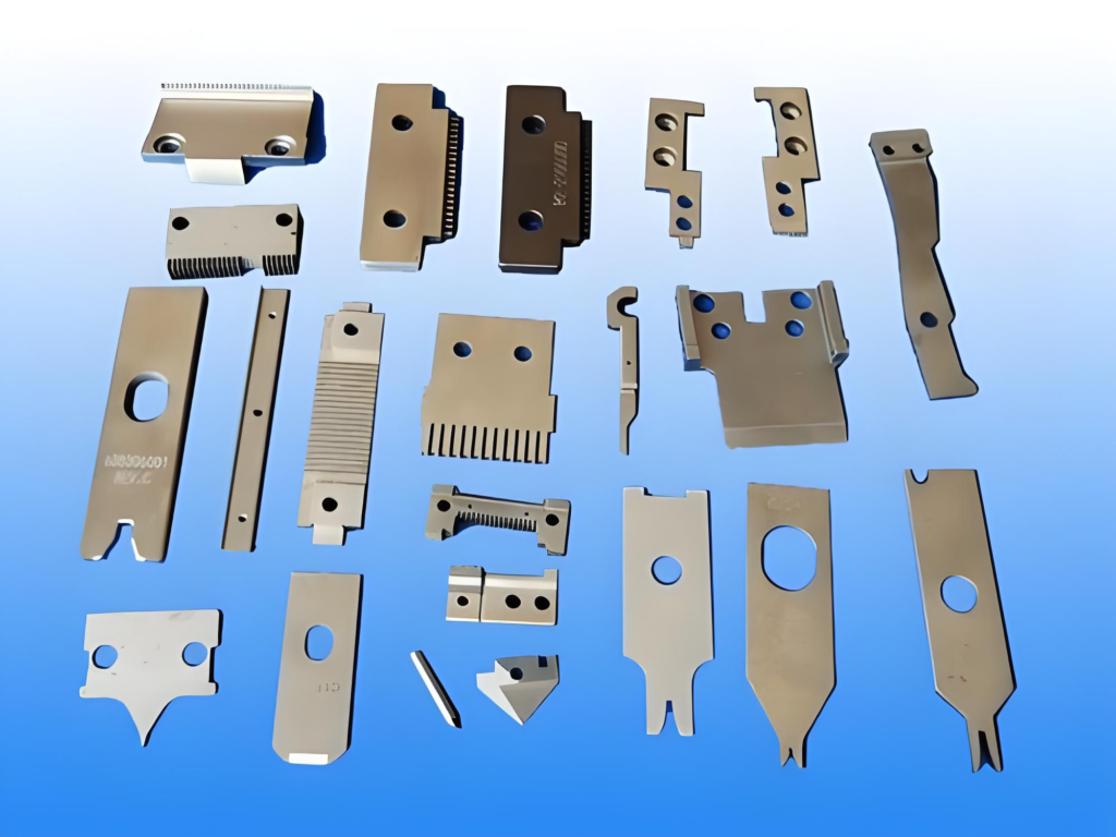
Full-Service Mold Fabrication
Specializing in stamping & injection mold inserts, cavities, cores and cutting edges. Stable mass production with 99.5%+ yield on 0.1mm slits, micro holes, deep grooves, custom punches and dies.
Zorapid Core Advantages, More Reliable for Long-Term Cooperation
Full Quality Control Throughout the Process
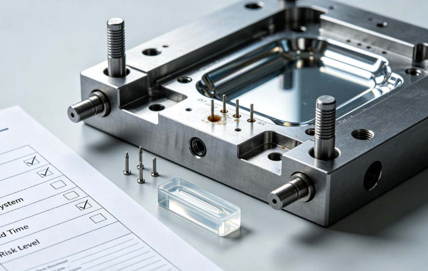
24/7 in-process quality control. Backed by 20+ years of precision manufacturing and ISO 9001 certification, Zorapid handles full in-house production: DFM review, material prep, programming, fixturing, cutting, post-processing and final inspection.
Efficient Delivery & Shortened Lead Time
Powered by CAD/CAM auto programming and smart production scheduling: complex samples in 1 day, small batches in 3 days, mass orders in 7 days. Pre-drilled wire holes, custom fixtures and dedicated wires in stock to cut lead time.
24-hour temperature-controlled workshop and round-the-clock shifts enable nonstop machining for thick, complex parts. Stable lead times guaranteed, with priority service for urgent orders.
Strict Quality Control
Full quality inspection with CMM, vision systems, roughness testers and micrometers. 100% full check on dimensions, geometric tolerances, surface finish and appearance. We supply complete inspection reports, material certifications and full traceability.
Cost Optimization
Material utilization is increased by over 30%. The ultra-narrow kerf (<0.3mm) effectively reduces material waste. One-stop forming simplifies working procedures, cutting labor and equipment costs.
Competitive pricing for long-term partnerships. Free DFM analysis and process optimization are provided.
In-depth industry expertise, serving high-end sectors
Core industries: Medical orthopedic implants & endoscope parts, aerospace engine and structural components, semiconductor tooling & fixtures, precision molds, and custom automation components.
Custom options: Low-volume production (1–100 pcs), mixed-batch manufacturing, rapid prototyping and reverse engineering. Strict drawing confidentiality, NDA available upon request.
Why clients choose Zorapid
- High-precision parts: Tolerance under ±0.005mm, Ra<0.2μm, for medical implants and semiconductor tooling.
- Hardened & heat-treated parts: HRC55+ hardened steel, carbide mold inserts.
- Complex shaped components: Narrow grooves, sharp corners, tapers, offset profiles and deep cavity mold parts.
- Thin-wall & deformation-prone workpieces: Under 0.5mm thickness, slim parts and ultra-thin shims.
- Rapid prototyping & low-volume production: Fast lead time, high precision for R&D, validation and pilot runs.
For EDM precision part manufacturing, choose Zorapid as your long-term reliable partner for accuracy, stability, efficiency, compliance and cost-effectiveness.
We solve tough machining challenges of high-precision, complex and hard material components, helping you boost quality, shorten lead times and cut costs.
What are the advantages of EDM cutting?
The core advantages of WEDM: zero cutting force, full machining on high-hardness conductive materials, ultra-high precision, intricate micro geometries, and outstanding process flexibility.
WEDM Wire Cut EDM Selection Reference Chart
Core Advantages Comparison

High-speed vs Low-speed Wire Cut Application

Preferred Application for Wire Cut EDM
- Workpiece hardness above HRC 55, difficult for conventional CNC
- Thin-wall, thin sheet, slender shaft & hollow structures with deformation risks
- Narrow grooves, micro holes, special-shaped apertures & complex inner profiles
- Burr-free surface with no secondary finishing needed
- Small-batch & multi-variety production with frequent design changes
- High-value alloy materials requiring high material utilization
Non-recommended Scenarios
- Non-conductive materials: plastic, common ceramic, glass
- Large material removal volume & large-area processing
- Extra-thick oversized parts with strict lead time requirements
WEDM Disadvantages:
Low processing efficiency, limited to conductive materials only, thermally affected altered layers, high cost and slow speed for large parts and rough machining.
WEDM Wire Cut EDM FAQ
What materials can WEDM process?
Only conductive metals. It works for hardened steel, carbide, titanium and superalloys, while non-conductive materials cannot be machined.
What is the tolerance accuracy?
High-speed wire cutting: ±0.01 mm. Low-speed wire cutting: up to ±0.001 mm for high-precision parts.
Will parts be deformed?
No mechanical cutting force, so thin-wall and fragile parts have zero deformation.
Does WEDM leave burrs?
Burr-free and tool-mark-free edges, no secondary deburring required.
Can it cut thick workpieces?
Yes, excessive thickness will cause wire vibration and reduce accuracy and surface finish.
What are the main disadvantages?
Low material removal efficiency, limited to conductive materials, and a slight heat-affected recast layer on the surface.
High-speed vs low-speed wire cut, which to choose?
High-speed for standard molds and cost-effective parts; low-speed for medical, aerospace and ultra-precision components.
Is post-processing necessary?
High-load and fatigue-critical parts need grinding to remove the recast layer; general parts can be used directly.