
Published:Zorapid.Ltd
Industry Background & Program-Level Requirements
Automotive connector components are classified as safety-related, high-precision, ultra-high-volume plastic parts for vehicle low-voltage body systems, ECU modules, sensors, ADAS, and new energy high-voltage electrical architectures. Typical automotive connector programs demand 500,000 to 20 million annual production volumes, requiring stable, repeatable, fully automated injection molding processes.
Unlike general consumer plastic parts, auto connectors require strict control over dimensional uniformity, pin hole roundness, locking retention force, insulation integrity, low warpage, zero flash, thermal cycle stability, and vibration resistance. For such massive volume demands, conventional cold runner molds and low-cavity hot runner molds cannot meet cost, capacity, and quality consistency requirements.
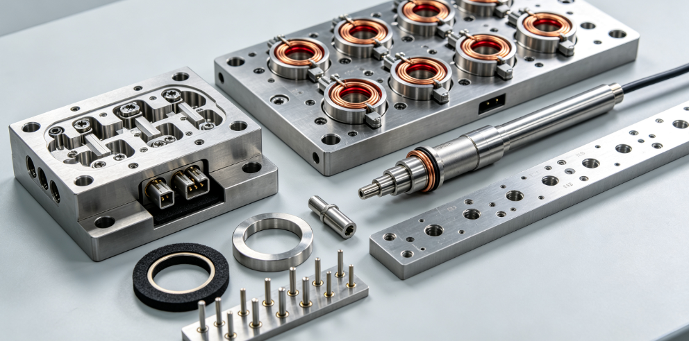
Multi-cavity valve-gated hot runner molds (16/32/64/128 cavities) have become the mandatory standard for Tier-1 automotive connector mass production.
Hot Runner System Full Technical Specification
Mandatory Valve-Gate Hot Runner Architecture
All automotive safety and mass-production connectors prohibit open hot runner systems.
Only servo/pneumatic sequential valve gate hot runner is allowed for the following reasons:
- Eliminates gate stringing, cold slugs, gate vestige, and post-processing trimming
- Achieves independent filling sequence control to suppress weld lines, air traps, and shear stress
- Balances melt velocity and pressure across all cavities
- Prevents short-shot, over-packing, and inconsistent shrinkage between cavities
- Preserves electrical insulation integrity by eliminating surface defects
Fully Balanced Manifold Design (Key to Multi-Cavity Consistency)
High-cavity molds rely entirely on manifold balance to avoid cavity deviation.
Professional auto connector manifold features:
- Geometry fully balanced H-type / X-type flow layout
- Zero dead corners, zero material retention zones to prevent coking, black specks, and resin degradation
- Mirror-polished internal flow channels to minimize shear heat for GF-filled and flame-retardant materials
- Multi-zone independent PID temperature control: manifold zone, plate zone, nozzle zone, tip zone
- Temperature accuracy controlled at ±1°C to ensure identical melt viscosity in every cavity
- High-temperature fatigue-resistant alloy material for long-run GF abrasion resistance
Unbalanced manifolds are the #1 cause of different dimensions, different warpage, different gloss, and unstable Cpk between cavities.
Nozzle & Mini Gate Technology for Thin-Wall Connectors
- Ultra-small pinpoint valve gate diameter: 0.4mm–0.8mm
- Gate placement strictly on non-functional non-mating surfaces
- Hardened valve pins and nitride-treated nozzle tips to resist glass fiber abrasion
- Synchronized valve opening/closing timing to eliminate filling delay deviation
- Low-shear tip design to avoid fiber breakage (critical for structural strength)
Mold Base, Cavity Steel & Structural Rigidity Standards
Steel Grade Selection (Long Life Mass Production)
- Cavity & Core: STAVAX / S136 Stainless Steel (48–52 HRC) Anti-corrosion, anti-flash, anti-abrasion, excellent polishing performance, stable dimension after millions of shots, ideal for PA66+GF, PBT+GF, FR flame-retardant materials
- Mold Base & Support Plates: H13 / 2311 High Toughness Steel High rigidity to resist deformation under long-term high injection pressure
High-Cavity Symmetrical Layout Principle
Standard mass-production cavity counts: 16 / 32 / 64 / 128 cavities
Strict layout rules:
- Full mirror symmetry to balance clamping force and thermal expansion
- Equal cavity spacing to guarantee identical cooling conditions
- Dense reinforced support pillar distribution to prevent mold deflection under 1500–1800bar injection pressure
- Isolated thermal zoning to avoid cross-row heat interference
- Uniform parting line stress distribution to eliminate partial flash
Anti-Deformation Mold Frame Structure
Auto connector thin-wall molding requires extremely high clamp rigidity.
All high-cavity molds adopt:
- Thickened top/bottom plates
- Integrated locking structure
- Optimized force balance design to avoid long-term mold fatigue, parting line gap expansion, and flash generation.
High-Precision Conformal Cooling System
Connector defects such as housing warpage, terminal hole ovality, lock hook deformation, assembly tight/loose tolerance are mostly caused by unbalanced cooling.
Professional auto mold cooling design includes:
- Conformal close-distance water lines following thin-wall contours
- Water-to-cavity surface distance strictly controlled 8–12mm
- Independent core/cavity temperature difference adjustment to balance asymmetric GF shrinkage
- Bubbler/baffle cooling for ultra-thin deep core pins (terminal holes)
- Row-by-row independent water circuits for high-cavity molds
- Full mold temperature uniformity controlled within ±0.5°C
Perfect cooling achieves:
- Zero ovality terminal holes
- Consistent lock hook elasticity
- Uniform shrinkage across all cavities
- Stable automated assembly yield
Ejection, Demolding & High-Speed Automation Structure
To adapt to 24/7 unmanned mass production:
- Multi-point balanced pin/sleeve ejection for every single cavity
- Uniform ejection force to avoid thin-wall white mark, deformation, and stuck parts
- Low-friction self-lubricating guide pillar and bushing system
- Synchronized valve gate closing + mold opening sequence for automatic clean gate break
- No manual trimming required
- Fully compatible with robot automatic picking, conveyor collection, and inline vision inspection
This structure drastically reduces labor cost and stabilizes PPM defect rate under long-run production.
Material-Specific Molding Process Design
PA66+15%/30% GF (Most Common Automotive Connector Material)
- Low-shear runner design to prevent fiber breakage and strength loss
- Sequential gating to transfer weld lines to non-critical areas
- Strict pre-drying control (moisture <0.02%) to eliminate bubbles and insulation failure
PBT+GF (High rigidity signal connectors)
- Fast cooling optimization to reduce brittleness and warpage
- Low-pressure filling to avoid internal residual stress
PA46 / High-temperature FR Grade (EV High-Voltage Connectors)
- High-temperature resistant hot runner system
- Anti-coking mirror runner finish
- Ultra-stable temperature control to avoid material decomposition and insulation risk
Multi-Cavity Consistency & CTQ Quality Control Standard
Automotive buyers’ strictest audit focus: cavity-to-cavity consistency
Full quality standards:
- All CTQ features (pin holes, locking structures, sealing ribs, assembly bosses) tolerance ±0.03–0.05mm
- Every single cavity maintains Cpk ≥ 1.33 during PPAP run
- No dimensional deviation between upper/lower rows, left/right cavities
- Uniform gloss, no individual cavity weld mark difference
- Zero flash on all parting lines after millions of shots
- Stable retention force, plug/unplug force consistency
To achieve this, the mold must have:
- Perfect flow balance
- Precise multi-zone temperature tuning
- Equal cooling efficiency for all cavities
- High-rigidity anti-deformation structure
Automotive PPAP, FMEA & Compliance Requirements
All multi-cavity hot runner connector molds must fully comply with IATF16949 automotive core tools:
PFMEA Coverage
- Unbalanced filling between cavities
- Hot runner coking / black spots
- Valve gate leakage / stringing
- Mold wear-induced flash
- Cooling difference warpage
- Thin-wall ejection deformation
- Multi-cavity dimensional inconsistency
PPAP Mandatory Documents
- Full 100% dimensional layout for all cavities
- Individual cavity SPC capability report
- Hot runner system certification
- Steel MTR hardness & material certification
- Mold thermal cycle stability test data
- Long-run process validation data
- 15-year document retention compliance
Mass Production Defect Analysis & Professional Solutions
- Cavity dimension inconsistency Cause: Unbalanced manifold flow, temperature deviation Solution: recalibrate valve sequence + fine-tune multi-zone temperature
- Black specks / carbon contamination Cause: runner dead zone, local overheating, poor polishing Solution: optimize flow path, mirror polish runner, adjust temperature zoning
- Connector warpage & hook distortion Cause: core/cavity cooling asymmetry Solution: adjust core-cavity temperature difference and cooling flow rate
- Terminal hole ovality Cause: slender core pin overheating Solution: install bubbler cooling for deep core pins
- Long-run flash generation Cause: mold fatigue, clamping deformation Solution: high-hardness steel + periodic parting line maintenance
Core Competitive Advantages of Multi-Cavity Hot Runner Molds
- Eliminate cold runner waste, saving massive high-cost engineering plastic material
- Shorten cycle time drastically for millions-shot mass production
- Zero gate vestige, eliminate secondary trimming labor
- Achieve ultra-stable multi-cavity consistency for PPAP approval
- Reduce warpage, improve assembly yield and vehicle electrical safety
- Support fully automatic unmanned 24-hour production
- Extremely low long-term PPM and stable quality
- Meet strict automotive thermal cycle, vibration, insulation and durability standards
FAQ
Why valve gate hot runner is mandatory for auto connectors?
Valve gate precisely controls filling timing, eliminates gate residue, balances multi-cavity flow, suppresses weld lines and internal stress, ensuring electrical safety, stable assembly force and zero-defect automotive quality.
Why high-cavity molds require fully balanced manifold?
Unbalanced flow leads to different filling speed, pressure and shrinkage in each cavity, causing dimension drift, warpage difference, gloss difference and PPAP failure.
Why use S136/STAVAX stainless steel for connector cavities?
Automotive GF-filled and flame-retardant resins are highly abrasive and corrosive. Hardened stainless steel ensures long-term anti-wear, anti-flash and dimensional stability for millions of shots.
What is the biggest technical difficulty for 64/128 cavity connector molds?
Synchronized filling balance, uniform cooling across all cavities, zero cavity deviation, long-term anti-wear stability, and consistent Cpk capability.
How does hot runner improve automotive PPAP pass rate?
Hot runner provides repeatable filling parameters, stable melt quality, consistent multi-cavity capability, zero waste process and low defect rate, fully meeting IATF16949 statistical quality requirements.
Can open hot runner be used for auto connectors?
No. Open hot runner causes stringing, vestige, unbalanced filling and unstable quality, which cannot pass automotive OEM quality audits and PPAP.


