
Zorapid Precision 5-Axis CNC Machining
If your shop runs full simultaneous 5-axis mills daily, you know programming missteps burn cash fast.
One bad CAM setup can trigger costly toolholder collisions, heavy chatter ripples, blown GD&T tolerances, or cycle times double what they should be.
Lots of programmers treat five-axis like a fancier 3-axis machine. That’s the root of nearly every failure. 5-axis adds rotary axes, tool vector control, machine kinematics, and singularity zones—variables 3-axis code never has to handle.
OEMs building blisks, medical implants, mold cores, and lightweight aerospace brackets rely on zero-fault five-axis code to hit tight deadlines and low scrap rates. Generic CAM default settings won’t cut it for complex freeform surfaces.
At Zorapid, our in-house CAM engineering team runs hundreds of five-axis jobs monthly across medical, aerospace, EV and tooling sectors. We’ve cataloged the seven most widespread programming mistakes our clients bring to us, paired with actionable, production-ready optimization workflows we use to eliminate each issue entirely.
No overly academic jargon. Every fix below is validated on our rigid five-axis machining centers, compatible with Mastercam, Fusion 360, PowerMILL, NX and CATIA. We’ll cover CAM setup, toolpath logic, post processor tuning, machine kinematics, simulation and cutting parameter optimization all in one guide.
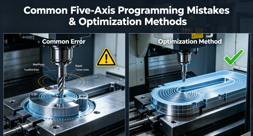
Why Five-Axis Programming Breaks So Easily
Before jumping into mistakes, let’s clarify what makes multi-axis code far less forgiving than standard 3-axis milling.
- Dual linear + rotary axis movement creates constant shifting tool angles; minor vector errors turn into gouging instantly.
- Machine pivot offsets, axis rotation limits and RTCP logic differ across every five-axis machine brand. Generic post processors output flawed G-code.
- Singularity zones (where rotary axes flip rapidly) cause violent feed jumps, surface scarring and machine stress if unprogrammed around.
- Extended tool stick-out for deep cavities amplifies deflection and chatter—far harder to compensate than short 3-axis tooling.
- Collision risks multiply: tool shank, holder, fixture, rotary table and spindle housing all can clash during tilting moves.
Top 7 Common Five-Axis Programming Mistakes + Full Zorapid Optimization Solutions
Each section clearly labels the error, its costly consequences, then step-by-step optimization methods deployed daily at Zorapid. Paragraphs capped at 3 sentences for high readability.
Using 3-Axis Programming Logic for Simultaneous 5-Axis Toolpaths
What programmers get wrong
They lock fixed Z heights, run vertical-only ballnose cuts, and ignore tool tilt/lead-lag angle control built into five-axis CAM modules. They treat rotary axes as an afterthought instead of a core cutting tool.
Costly side effects
Uneven stepover across curved surfaces, heavy chatter on steep walls, inconsistent Ra finish, extra setups stacking tolerance errors, and bloated cycle times. Thin aerospace walls bend under uneven side cutting force.
Zorapid Full Optimization Fix
- Switch to tilted lead-lag tool axis strategies for all freeform finishing: set 5°–12° lead angle to keep the cutter’s sweet spot engaged with material, avoid center-point rubbing of ballnose tools.
- Program single-datum full-contour machining wherever possible to cut setup count from 3–4 down to one. Eliminate tolerance stack-up from re-fixturing.
- Separate 3+2 roughing from full simultaneous 5-axis finishing: rough stock removal in locked rotary positions for speed, then deploy continuous vector 5-axis only for critical surfaces.
- Use constant chip load five-axis toolpaths; CAM automatically adjusts feed rate as tilt angle changes to maintain even cutting force across complex curves.
Disabled or Half-Baked Full Assembly Collision Checking in CAM
What programmers get wrong
They only simulate the cutting tip, ignoring toolholder, shank, spindle nose, fixture jaws, rotary table and workpiece stock. Many skip collision simulation entirely before posting G-code.
Costly side effects
Catastrophic toolholder crashes ruining expensive carbide tooling, scrap high-value aerospace/titanium blanks, bent machine rotary axes, and multi-hour downtime for repairs. Near-miss collisions leave hidden gouges on finished parts that fail CMM inspection.
Zorapid Full Optimization Fix
- Mandate full assembly collision detection inside CAM before posting any five-axis program: load complete tool holder model, fixture 3D CAD, raw stock and machine travel limits.
- Set safety retract planes 10–15 mm above the maximum rotated workpiece height. Avoid low retracts that swing holders into clamps during rotary repositioning.
- Run independent Vericut machine simulation for all complex five-axis jobs, not just built-in CAM preview. Vericut catches kinematic offset errors CAM internal sims miss.
- Program short intermediate safe tilt moves when crossing high-risk fixture zones; avoid large single rotary jumps over workpiece edges.
Uncalibrated Post Processors & Ignoring RTCP Kinematics
What programmers get wrong
They use generic universal five-axis post processors without matching their exact machine pivot offset, axis rotation direction, soft travel limits and RTCP (Rotation Around Tool Center Point) settings. Many forget to enable RTCP in the G-code header.
Costly side effects
Tool tip positional drift ±0.02–0.08 mm, dimensional GD&T failures, random gouging on deep cavities, axis overtravel alarms mid-cut, and inconsistent part accuracy across identical machine models.
Zorapid Full Optimization Fix
- Build machine-specific custom post processors calibrated to exact pivot length, A/B/C axis rotation limits and controller brand (Siemens, Haas, Fanuc). Re-test post after every CAM software update.
- Hardcode RTCP activation (G128 / G255 / RTCP ON) at the start of every simultaneous five-axis program; lock RTCP mode for all finishing toolpaths.
- Input accurate tool length & radius compensation offsets in both CAM and machine controller; never rely on rough manual probe measurements for precision five-axis jobs.
- Add axis soft-limit clamps inside post processor to block rotary overtravel before code hits the machine.
Poor Tool Orientation & Singularity Zone Ignorance
What programmers get wrong
They let CAM auto-generate unconstrained tool vectors that pass through machine singularity points (where rotary axes flip 180° instantly). No tilt angle limits or singularity avoidance rules applied.
Costly side effects
Extreme feed rate spikes, violent machine shudder, deep wave chatter marks across critical surfaces, spindle load surges, and inconsistent dimensional accuracy on symmetrical parts like impellers.
Zorapid Full Optimization Fix
- Enforce hard minimum/maximum tilt angle limits inside CAM to steer tool vectors clear of singularity bands. Restrict rotary axis rotation range to avoid flip zones entirely when geometry allows.
- Insert micro intermediate tilt moves to bypass singularity hotspots on blisks, turbine blades and spherical molds. Force small gradual angle shifts instead of single large jumps.
- Activate controller singularity smoothing parameters (Siemens REACH flip avoidance, Haas axis speed dampening) to auto-lower feedrate near high-risk zones.
- For symmetrical parts, split toolpaths into left/right segmented cutting to prevent the machine from crossing central singularity regions.
Unoptimized Roughing Strategy & Uneven Stock Allowance
What programmers get wrong
They run full-depth straight pocket roughing on complex five-axis cavities, leave inconsistent residual stock (0.05 mm to 0.8 mm variation) across walls and radii, and skip rest-machining operations.
Costly side effects
Finishing passes take excessive heavy cuts that bend thin walls, severe chatter on uneven stock zones, premature tool wear, extended finishing cycle times, and inconsistent surface roughness across batches.
Zorapid Full Optimization Fix
- Deploy five-axis adaptive trochoidal roughing for all deep complex cavities; constant radial engagement cuts heat and side deflection drastically.
- Lock uniform semi-finish stock allowance (0.1–0.15 mm) on every feature before final finishing runs. Run dedicated rest-machining toolpaths to clear leftover stock in tight radii.
- Layer roughing with shallow step-down depths (0.2–0.4 mm per pass) on thin-wall aerospace components to control residual stress and part distortion.
- Separate roughing operations by tilt angle to avoid mixing heavy stock removal with high-risk simultaneous five-axis moves.
Excessive Tool Overhang & Ignoring Tool Rigidity Rules
What programmers get wrong
They pick long extended shank tools by default for deep cavities, ignore tool stick-out rigidity ratios, and skip short stub tool alternatives where geometry permits.
Costly side effects
Severe tool deflection, chatter ripples on vertical curved walls, tapered part profiles, blown tight tolerance features, and 3–5x faster carbide edge wear.
Zorapid Full Optimization Fix
- Follow Zorapid internal rule: limit tool overhang to maximum 3× tool shank diameter wherever part geometry allows. Swap to short stub cutters first before selecting extended reach tools.
- Use lollipop undercut end mills only when short tools cannot access deep undercuts; program lighter feed rates automatically for all long-overhang toolpaths.
- Add tool tilt offsets to shorten required stick-out: tilt spindle away from deep cavity walls to cut needed extension length.
- For thin-wall titanium & Inconel parts, add secondary support fixtures to reduce workpiece vibration paired with short rigid tooling.
Unsmooth Tool Transitions & Missing Axis Smoothing Parameters
What programmers get wrong
They generate toolpaths with sharp 90° direction changes, no arc blend transitions, and fail to activate machine controller axis acceleration smoothing. Rapid retracts run at full speed near finished surfaces.
Costly side effects
Visible witness lines across freeform surfaces, uneven dimensional drift at path transition points, machine jerk triggering micro-gouges, and longer overall cycle times.
Zorapid Full Optimization Fix
- Enable CAM arc blending on all finishing toolpaths; replace sharp directional corners with smooth tangential arc transitions to eliminate axis jerk.
- Tune machine controller look-ahead blocks and acceleration smoothing parameters to maintain consistent feed speed across complex curves.
- Program slow, gentle lead-in/lead-out arcs on all critical sealing and aerodynamic surfaces; avoid straight plunge entry onto finished geometry.
- Reduce rapid traverse feedrate within 5 mm of any workpiece surface to eliminate accidental micro-scratches from fast spindle movement.
Zorapid Real-World Five-Axis Programming Case Study – Aerospace Blisk Machining
A tier 1 aerospace OEM reached out with consistent five-axis part failures on aluminum blisk components. Their original programming workflow hit three major pain points:
- Generic uncalibrated post processor causing ±0.06 mm blade profile drift
- Disabled singularity avoidance creating heavy chatter waves on airfoil surfaces
- No rest-machining roughing, uneven stock leading to thin blade deflection during finishing
Zorapid deployed our full seven-step five-axis programming optimization workflow:
- Built custom blisk-specific post processor matched to their 5-axis machine pivot kinematics with locked RTCP logic
- Added tilt angle boundary constraints + segmented toolpaths to bypass singularity flip zones
- Adaptive trochoidal roughing + dedicated rest-machining to hold uniform 0.12 mm stock allowance
- Full Vericut assembly collision simulation for every program revision
- Lead-lag tilted tool axis finishing with arc-blended smooth transitions
- Short rigid stub ballnose cutters to minimize tool deflection
- Controller smoothing parameter tuning to stabilize feed across complex airfoil curves
Measurable client results post-optimization:
- Profile dimensional error reduced from ±0.06 mm to stable ±0.005 mm
- Chatter witness marks eliminated entirely from blisk airfoil surfaces
- Total five-axis cycle time cut by 28% per blisk
- Tool wear consumption dropped 42% via consistent chip load control
- Zero collision or gouge scrap incidents over 6-month production batch runs
Quick Troubleshooting Cheat Sheet – Match Defect to Programming Fix
Skim this fast-reference list to diagnose five-axis programming errors mid-job setup instantly:
- Wavy chatter ripples across curved freeform surfaces Root Cause: Singularity zone jumps, long tool overhang, no lead-lag tilt angle Optimization: Restrict rotary tilt range, switch to short stub tools, add 8° lead angle finishing
- Random gouges on deep cavity radii Root Cause: Disabled full assembly collision check, generic uncalibrated post processor Optimization: Run Vericut full simulation, deploy machine-specific custom post processor
- Dimensional drift varies across identical parts Root Cause: RTCP disabled, incorrect pivot offset in CAM Optimization: Hardcode RTCP activation, re-calibrate machine pivot length in CAM library
- Extremely long cycle times with excessive air cutting Root Cause: Unsegmented toolpaths, no rest-machining, oversized retract travel Optimization: Split toolpaths by tilt angle, add rest roughing, lower safe retract height limits
- Sudden machine rotary axis overtravel alarms Root Cause: Missing axis soft limits in post processor, unconstrained CAM tilt angles Optimization: Lock rotary min/max tilt in CAM, add overtravel clamps inside post code
Why Zorapid Delivers Zero-Defect Optimized Five-Axis Programming Competitors Can’t Match
Most CNC shops only tweak one piece of the five-axis puzzle—either CAM toolpaths or simulation alone. Our integrated full programming & machining system eliminates every common error source from quote to final G-code delivery:
- Dedicated five-axis CAM engineering team with 10+ years experience on blisks, medical implants, mold cores and EV lightweight parts
- Custom machine-calibrated post processor library for all our simultaneous 5-axis milling centers (Siemens & Fanuc controlled)
- Mandatory dual simulation workflow: internal CAM collision check + independent Vericut full machine kinematics verification
- Standardized five-axis programming template library preloaded with singularity avoidance, lead-lag tilt rules and uniform stock allowance logic
- In-house rigid 5-axis machining centers with optimized controller smoothing & RTCP kinematic tuning
- Free upfront DFM review for all complex multi-axis parts to flag programming risks before CAD hits CAM software
- ISO 9001 & AS9100 certified precision workflow with full CMM GD&T validation post five-axis machining
FAQ
Is simultaneous full 5-axis always better than 3+2 positional five-axis roughing?
No. Use locked 3+2 rotary positioning for heavy rough stock removal—it’s faster, generates more stable cutting forces and avoids singularity jumps. Reserve full simultaneous five-axis only for finishing complex curved aerodynamic, medical or mold surfaces.
Do I need Vericut simulation if my CAM software has built-in collision preview?
Yes. Native CAM simulation only calculates toolpath geometry, while Vericut replicates full machine kinematics, pivot offsets, rotary axis movement and post-processed G-code behavior. It catches post processor and RTCP errors CAM internal previews miss entirely.
How much cycle time can five-axis programming optimization cut from standard jobs?
For most complex freeform parts, consistent optimization reduces total machining cycle time by 20–35% while cutting tool wear and scrap rates simultaneously. Blisk, impeller and deep mold cavity jobs see the largest time savings.
Can singularity zone programming errors permanently damage five-axis machine rotary axes?
Long-term repeated unconstrained singularity flips create massive mechanical stress on A/B/C rotary bearings, accelerating wear and triggering costly precision loss over time. Adding tilt angle limits is low-cost machine maintenance protection.
Conclusion
Every common five-axis programming error traces back to one core oversight: treating multi-axis code like upgraded 3-axis milling. Successful five-axis machining demands aligned CAM toolpath logic, calibrated post processors, singularity avoidance, full collision simulation, rigid tooling rules and smoothed axis movement all working together.
If your current five-axis programming workflow struggles with tool collisions, chatter surface defects, unstable GD&T tolerances, bloated cycle times or high scrap rates, Zorapid’s standardized optimization framework eliminates these recurring production headaches.
We offer complimentary CAD DFM & CAM programming reviews for all complex five-axis OEM components, plus fast prototype and volume precision 5-axis CNC machining quotes for aerospace, medical, EV and mold manufacturing clients.
Upload your part CAD file today to receive custom multi-axis programming optimization guidance tailored to eliminate five-axis machining errors on your next production run.


