
Published by Zorapid
If you’re a mechanical engineer, product designer, or procurement lead sourcing custom CNC parts, you’ve lived this pain:
You send clean CAD files, lock in a production timeline, then get hit with last-minute delays, inflated quotes, or scrapped first-run batches. Almost every time, the root cause is skipping formal DFM analysis before CNC machining kicks off.
At Zorapid, we’ve run 20,000+ CNC jobs across medical implants, aerospace brackets, EV connectors and automation hardware for US and EU clients over 20+ years. Our engineering team runs a mandatory full DFM breakdown on every drawing before cutting a single block of stock metal or plastic. The numbers speak for themselves: clients who follow our core DFM rules slash part costs by 25–40%, cut lead times nearly in half, and scrap rates drop below 0.8% vs industry average 12% for unreviewed designs.
DFM doesn’t mean rewriting your entire functional design. It’s small, targeted geometry tweaks, tolerance adjustments and drawing fixes that remove manufacturing roadblocks—without sacrificing how your part performs. Today we’re breaking down our non-negotiable core DFM analysis rules we apply to every CNC project pre-production.
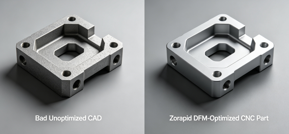
Audit Tolerances – Only Tighten What Functionally Needs It
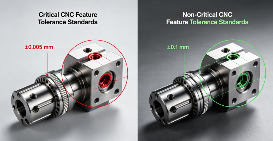
This is the costly DFM mistake we see from Western design teams: blanket ultra-tight micron tolerances across every dimension, even non-mating, non-load-bearing surfaces.
What Goes Wrong Without DFM Audit
- ±0.005mm tolerances on non-contact surfaces force slower feed rates, extra finishing passes, round-the-clock CMM inspection and premium precision CNC machines. Each unnecessary tight tolerance adds 15–60 minutes per piece of cycle time.
- Stacked tight tolerances create impossible fit variation, triggering full batch scrap on first production run.
- Ra 0.2μm mirror finish callouts on hidden internal cavities add secondary grinding operations that tack on hundreds of dollars per order.
Zorapid DFM Analysis Standard Rule
- Separate features into two groups: critical-to-function (CTF) and general non-critical.
- Restrict tight tolerances (≤±0.01mm, Ra ≤0.8μm) exclusively to bearing seats, sealing faces, assembly datums and press-fit holes.
- Apply industry standard loose tolerances (±0.1mm, Ra 1.6–3.2μm) to all non-machining critical surfaces.
- Clearly label GD&T datums to avoid tolerance stack-up confusion for our machinists.
Real Quick Client Example
A German medical startup sent an aluminum fixture drawing with ±0.003mm tolerance across all 28 dimensions. Our DFM engineer flagged 22 non-critical features, relaxed their tolerances to standard ±0.1mm, and their per-unit quote dropped $92 immediately. No functional performance loss whatsoever.
Fix Internal Geometry – Ditch Sharp Corners & Thin Unstable Walls
CAD software lets you draw perfect 90° internal sharp corners, but round CNC end mills physically cannot machine them without massive tradeoffs. Thin walls warp, chatter and snap mid-cut—another preventable flaw caught during pre-production DFM analysis.
Two Non-Negotiable Geometry DFM Checks We Run
Internal Corner Radius Standard
All internal pockets, slots and cavities must carry a fillet radius matching standard end mill sizes (R1mm, R2mm, R3mm most common).
- Sharp corners force tiny fragile micro-tools, slower cutting speeds, heavy tool wear and chatter ripples on finished surfaces.
- If your design requires near-sharp corners, our DFM team flags this upfront and quotes costly secondary wire EDM instead of hiding the expense post-production.
Minimum Uniform Wall Thickness
We validate wall thickness ratios for every material during DFM review:
- Aluminum (6061-T6 / 7075-T6): minimum 0.5mm uniform wall
- Stainless / Titanium / Inconel: minimum 0.8mm uniform wall
- Engineering plastics (PEEK, GF-PA66): minimum 0.3mm uniform wall
Uneven wall thickness creates thermal warpage during machining and post-heat treatment. Our engineers add subtle ribbing or thickness equalization during DFM optimization to eliminate distortion risk.
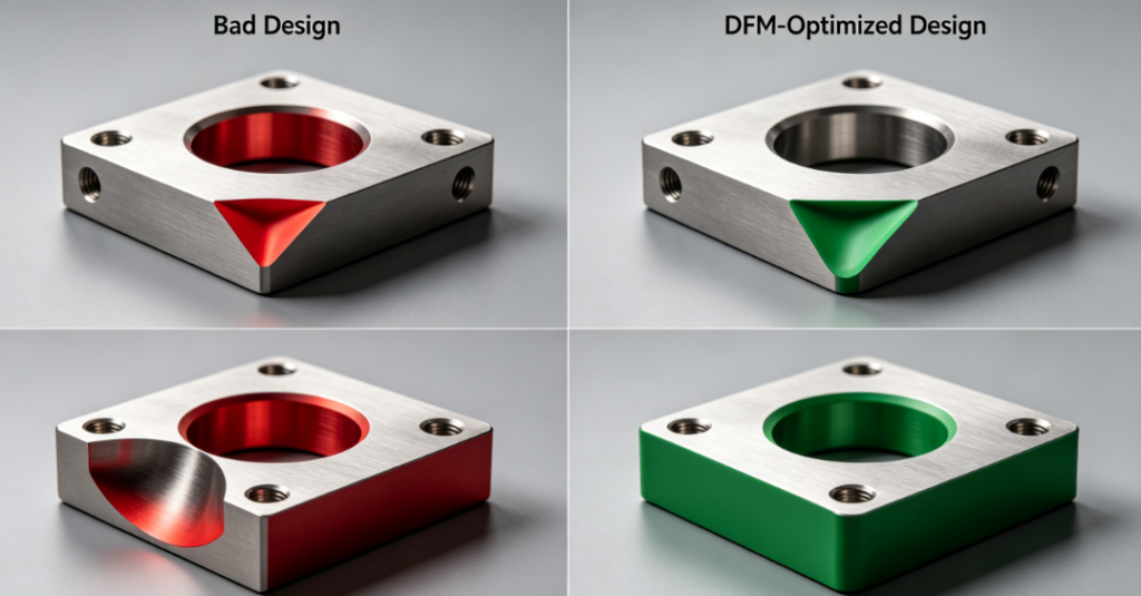
Standardize All Holes, Threads & Cavity Depth Ratios
Odd custom hole diameters, random thread sizes and overly deep blind cavities are major DFM red flags that extend lead times and raise pricing. Our third core analysis rule locks all cut features to industry standard tool dimensions before production sign-off.
DFM Standard Limits We Enforce
- Hole depth-to-diameter ratio: Max 4:1 for blind holes; through-holes preferred where design allows. Deeper ratios require long overhang tools that deflect and ruin dimensional accuracy.
- Holes must match metric standard drill sizes (3mm,4mm,5mm,6mm,8mm,10mm) or imperial fractional sizes (1/4”, 5/16”, 3/8”). Random custom hole sizes demand custom tooling with 3–7 day lead time delays.
- Thread specifications: Stick to standard M3–M12 metric / #6-32 to 1/2-13 UNC taps. Tiny threads below M3 get a DFM recommendation for threaded inserts to avoid tap breakage mid-production.
- Cavity width-to-depth ratio: Never exceed 3:1 without special long-reach tooling add-ons.
Quick Win DFM Adjustment Example
A US automation client designed a blind pocket 12mm deep × 2mm wide (6:1 ratio). Our DFM team widened the pocket to 4mm, dropped the ratio to 3:1, removed long tool surcharges and cut machining cycle time by 65%.
Verify Full Tool Accessibility & Minimize Multi-Setup Operations
Every extra machine setup adds labor time, cumulative alignment error and higher production cost—this accessibility audit is a central pillar of our pre-production DFM workflow.
What Our DFM Engineers Check for Tool Access
- All critical machined features must be reachable from primary X/Y/Z axes without part re-fixturing (3-axis preferred over 5-axis where geometry permits).
- No recessed features blocked by tall bosses, standoffs or raised framing—tools need clear vertical clearance for full cuts.
- Group identical features (all holes, all slots) on single planes to cut down tool change cycles.
If your original CAD requires 4+ separate setups or full 5-axis machining for simple geometry, our team proposes minor part orientation redesigns during DFM analysis to drop back to cheaper, faster 3-axis operations.
Cost Impact Real Data
One aerospace customer’s original bracket needed two full 5-axis setups ($148 per unit). Our DFM tweak repositioned angled holes onto primary planes, shifting production to single-setup 3-axis machining and saving $71 per component at volume runs.
Material DFM Check – Match Grade, Stock Size & Machinability
Poor material selection is often overlooked in basic design work, but our DFM process runs a full material machinability audit before we lock raw stock orders.
Three core material DFM verification steps:
- Confirm stock bar/plate dimensions match standard industry blank sizes. Custom oversized stock creates massive material waste and extra roughing passes.
- Cross-check material machinability vs your feature complexity:
- 6061 aluminum = fast, low tool wear, ideal for high-volume simple CNC parts
- 316 stainless / Ti-6Al-4V = slow feed rates, higher tool cost, requires extra cooling
- High-temperature alloys (Inconel 718, 17-4PH) = strict DFM wall & depth limits to avoid tool burnout
- Flag heat treatment conflicts: Materials that shrink/distort post-hardening get geometry allowances added during DFM analysis to hold final tolerances.
We never substitute materials without client approval, but our DFM report always lists lower-cost, equally functional alternative grades if your original selection over-engineers the component.
Surface Finish & GD&T Drawing Completeness Audit
Incomplete engineering drawings create endless back-and-forth clarification emails that delay production launches—our DFM analysis rule mandates full drawing validation before any CAM programming starts.
Mandatory drawing checks in our DFM workflow:
- Explicit Ra surface finish callouts for every machined face (no vague “smooth finish” text).
- Fully defined primary/secondary/tertiary GD&T datums for all precision assemblies.
- Clear marking for post-processing: anodize, passivation, bead blast, laser engraving, thread inserts.
- Full material heat treatment, certification and compliance notes (ISO 13485 medical, AS9100 aerospace, RoHS EV).
Missing surface finish or GD&T details lead to rework batches; our DFM report flags every incomplete drawing item in a numbered list so your engineering team can resolve in one round of edits.
Eliminate Unnecessary Undercuts & 5-Axis Mandatory Geometry
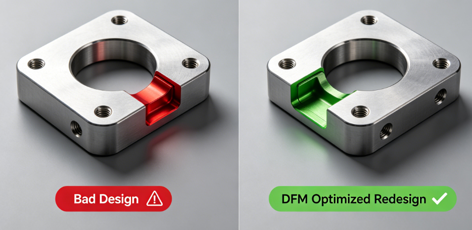
Undercuts require specialty form tools or full 5-axis CNC machining, both of which raise pricing and extend lead times significantly. Our seventh core DFM rule targets removing non-essential undercut geometry wherever functional design allows.
DFM Optimization Fixes for Undercuts:
- Convert blind undercut slots to fully through-cut features to eliminate special tooling.
- Split single complex integrated housings into two simple assembled components if undercuts can’t be removed from the monolithic design.
- If undercuts are non-negotiable, our DFM report clearly separates mandatory 5-axis features to quote accurate lead time and cost upfront.
Real Zorapid Client Case Study: DFM Review Cut Cost 38% & Lead Time 40%
A US EV startup reached out to Zorapid for 2,000 custom aluminum battery terminal brackets, submitting raw CAD files without internal DFM checks. Their initial target lead time was 4 weeks, and preliminary quote hit $116 per unit.
Our engineering team ran our full 7 core DFM analysis rules and delivered a free optimization report with 8 actionable design tweaks:
- Relaxed 19 non-critical dimension tolerances from ±0.004mm to standard ±0.1mm
- Added R2mm radii to all internal sharp pocket corners
- Widened thin 0.4mm walls to uniform 0.6mm thickness to eliminate warpage
- Adjusted blind hole depth ratio from 5:1 down to acceptable 3:1
- Repositioned angled mounting holes to avoid second 5-axis setup
- Removed non-essential rear undercut slot by converting to through feature
- Switched custom odd-sized holes to standard 6mm drill dimensions
- Simplified surface finish requirements on hidden rear faces from Ra0.4μm to Ra3.2μm
After implementing all DFM changes:
- Per-unit production cost dropped 38% to $72
- Total lead time shrank 40% from 28 days to 17 days
- First production batch scrap rate hit 0% Client’s engineering lead later told us the DFM review saved their project over $88,000 at full production volume. This is the consistent ROI our pre-production DFM analysis delivers for every Western OEM partner.
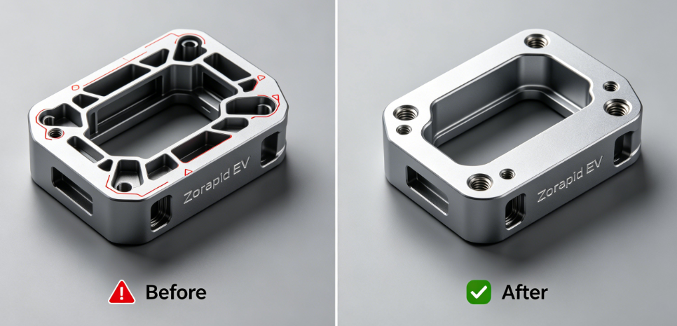
Our Step-by-Step Zorapid Pre-Production DFM Analysis Workflow
To make these core rules repeatable for every client order, we follow a fixed 6-stage DFM breakdown before CNC stock cutting:
- CAD File Import & Feature Extraction (STEP/IGES native support)
- Tolerance & GD&T Layer Audit (Rule 1 execution)
- Internal Geometry, Wall & Cavity Ratio Scan (Rules 2 + 3)
- Tool Access & Setup Count Simulation (Rule 4)
- Material Machinability & Stock Size Validation (Rule 5)
- Undercut, Surface Finish & Drawing Completeness Final Check (Rules 6 +7)
Once all seven core DFM rules pass our engineering sign-off, we release the job to CAM programming and CNC production. If conflicts exist, we send a visual annotated DFM report with marked CAD screenshots and cost/lead time impact breakdowns for your team to approve edits.
Quick CNC DFM Cheat Sheet
Save this reference for your next CAD design draft—our condensed core DFM rules for fast pre-submission self-review:
- Tight tolerances only for mating / sealing surfaces
- All internal corners = standard radii, no sharp 90° angles
- Uniform walls above material minimum thickness limits
- Blind hole depth ≤4× diameter, standard drill/thread sizes only
- Maximize 3-axis accessible features, cut multi-setup operations
- Match standard raw stock material blank dimensions
- Remove all non-functional undercuts to avoid 5-axis surcharges
- Fully label GD&T datums and explicit Ra surface finishes on drawings
FAQ
Can DFM changes break my part’s functional performance?
Never—our DFM engineers only propose geometry and tolerance adjustments that preserve all your critical functional specs. Every optimization includes a clear note explaining zero impact on fit, strength or sealing performance. We never alter load-bearing, assembly-critical features without written client approval.
How long does Zorapid’s full pre-production DFM analysis take?
For standard single-component CAD files: 12–24 hours turnaround on our complimentary DFM review service. Complex multi-part assemblies or aerospace/medical high-precision designs take 24–48 hours for full breakdown.
Already have a tight deadline—can I skip DFM analysis to speed production?
We strongly advise against it. Unreviewed designs frequently hit mid-production roadblocks that add 5–10 days of delays, which far outweighs the single day DFM review timeline. Our free analysis is built to eliminate last-minute production hold-ups.
Do you offer DFM consulting for early-stage conceptual CAD drafts?
Absolutely. Zorapid provides NPI-stage DFM consultation for prototype designs before you finalize drawings, which delivers the largest cost and timeline savings for mass production runs.
Wrap-Up
Every hour you invest in pre-production DFM analysis before CNC machining pays massive dividends: lower per-unit cost, faster delivery windows, zero costly scrap batches and consistent repeatable part quality across prototype and volume manufacturing.
The seven core DFM rules we covered today are the exact checklist our 20+ year precision engineering team applies to every medical, aerospace, automotive and automation component for US and EU OEM clients. At Zorapid, DFM analysis isn’t an optional add-on—it’s a mandatory free step built into every CNC machining quote we deliver.


