
Published by: Zorapid.Ltd
You nail the CNC program, hold tight dimensional tolerances, and get perfect Ra values right off the mill.
Then post-processing ruins everything.
You finish deburring, polishing or anodizing, and suddenly you see blotchy color, hidden residual burrs, fine scratches, chipped edges, and hard-to-clean oil stains.
At Zorapid’s 3,000㎡ precision workshop, we run one-stop CNC machining + full post-finishing every day.
We find that 78% of cosmetic and functional failures do NOT start on the CNC machine. They happen during secondary finishing.
A tiny mistake in deburring, cleaning, blasting or coating can turn qualified machined blanks into rejected batches, especially for aluminum 6061, 7075, 17-4PH stainless steel and titanium alloy components for medical, semiconductor and automation equipment.
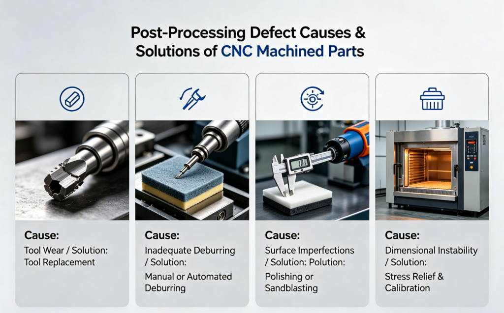
This practical troubleshooting guide breaks down the 7 most frequent post-processing defects on CNC machined parts. We list clear root causes, then shop-tested solutions you can apply immediately on your NPI prototypes and mass orders.
Why Post-Processing Creates New Defects Even If CNC Machining Is Perfect
Many designers separate CNC cutting and secondary finishing into two independent jobs. This is the biggest trap.
Three carry-over issues from milling trigger nearly all post-treatment problems:
- Hidden micro-burrs left on hole exits and intersecting cross holes Small burrs you cannot see with naked eyes get pressed into the surface during tumbling or sanding, creating permanent indentations.
- Residual coolant, cutting oil and chip dust trapped in deep cavities and threaded holes These contaminants cause staining, pinholes and poor coating adhesion during anodizing or powder coating.
- Surface texture inconsistency from tool marks and built-up edge (BUE) Even subtle tool chatter will turn into obvious color streaks after dye anodizing.
Post-processing only amplifies these small flaws. Sanding, tumbling and chemical baths do not fix original surface issues — they make them worse.
Residual Burrs & Hidden Cross-Hole Burring
Defect Appearance
Sharp leftover edges on outer profiles; loose metal flakes inside tapped holes and intersecting cross bores. Deburring leaves partial burrs that break loose during assembly and block fluid channels.
Root Causes
- The CNC exit edge creates roll-over burrs, especially on aluminum and soft steel. Manual filing only cleans outer surfaces and cannot reach internal crossing holes.
- Vibratory tumbling media cannot fully reach deep internal passages, so inner burrs stay untouched.
- Operators rush deburring before cleaning chips out of blind cavities. Chips get stuck and form secondary burrs.
Zorapid Proven Solutions
- Add in-machine chamfering before parts come off the CNC. Use chamfer mills to break sharp edges and reduce burr formation from the cutting stage.
- Use abrasive nylon brush deburring for cross holes. Rotating brushes reach internal intersections without damaging precision dimensions.
- Separate batches: Manual deburring only for external edges; automated electrochemical deburring for deep cross holes on hydraulic valve bodies.
- Implement air blowing + ultrasonic cleaning right after deburring to flush out loose metal particles.
Polishing Scratches & Uneven Sanding Texture
Defect Appearance
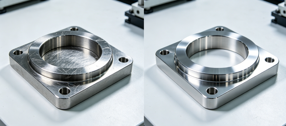
Fine linear scratches across flat surfaces; patchy matte and glossy zones after hand sanding. These marks stay visible even after clear coating.
Root Causes
- Operators jump from coarse grit to fine grit without progressive grading. Deep coarse grit grooves cannot be removed with fine sandpaper.
- Hard foreign particles get trapped between sandpaper and the workpiece, dragging long scratches across the part surface.
- Thin-walled parts flex under hand pressure, creating wavy uneven surfaces during manual polishing.
- Built-up edge from CNC machining leaves hard metal smears that tear abrasive pads during finishing.
Zorapid Proven Solutions
- Strict grit progression: 180# → 400# → 800# → 1200# without skipping grades.
- Switch from hand sanding to fixture-held automated buffing for flat precision faces to eliminate flex deformation.
- Remove all BUE smears with pre-blasting before polishing; clean every fixture and sanding pad between batches.
- Use soft foam-backed abrasives for contoured 3D surfaces to avoid edge rounding and scratching.
Edge Chipping & Corner Rounding Beyond Tolerance
Defect Appearance
Sharp corners get over-rounded; thin outer edges chip and break during vibratory finishing. Critical sharp features lose dimensional accuracy after tumbling.
Root Causes
- Oversized abrasive media pounds on sharp part corners during long tumbling cycles.
- Thin-wall CNC components have low rigidity. Continuous vibration causes micro-cracks on sharp edges.
- Parts collide with each other inside the vibratory bowl, leading to edge chipping on small precision features.
Zorapid Proven Solutions
- Match media size to feature geometry: Use small ceramic pin media for small corners; large cone media for flat surfaces.
- Wrap delicate thin-wall parts in rubber fixtures before tumbling to isolate sharp edges from abrasives.
- Split the process: Short 30-minute deburr cycles first, then shift to fine polishing media to avoid over-rounding.
- Add small 0.2mm protection chamfers on sharp corners during CNC programming to absorb tumbling impact.
Anodizing Stains, Blotches & Uneven Dye Absorption (Aluminum CNC Parts Nightmare)
Defect Appearance
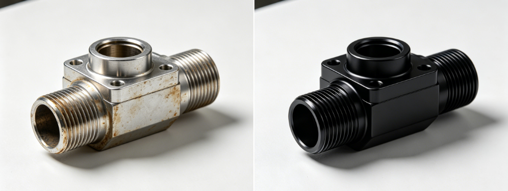
Dark spots, streaky color variation, cloudy patches on 6061 / 7075 aluminum after dye anodizing. Tool marks that were invisible on raw metal turn into obvious dark lines after coloring.
Root Causes
- Residual cutting oil, coolant residue and polishing compound seep into tiny surface pores. Chemical pre-treatment cannot fully remove these contaminants, creating bare stained areas.
- Inconsistent surface texture from chatter marks and uneven deburring makes the oxide layer thickness non-uniform. Dye sticks heavier on rough zones.
- Manual sanding creates mixed surface roughness; bead blasting pressure varies across the batch, leading to patchy anodizing results.
- Intergranular contamination from dirty ultrasonic cleaning baths.
Zorapid Proven Solutions
- Three-stage cleaning flow after machining: Degreasing → alkaline wash → ultrasonic pure water rinse, with full drying before entering the anodizing line. No oil residue allowed.
- Standardize pre-anodizing surface prep: If you bead blast, lock air pressure, media size and cycle time for every part in the batch. Never mix hand-sanded and blasted surfaces on the same component.
- Eliminate BUE and tool chatter in CNC finishing passes. Keep step-over below 0.08mm to achieve consistent raw surface texture.
- Mask threaded holes and deep blind holes to trap no chemical liquid during anodizing.
Residual Stains & Water Spots After Cleaning
Defect Appearance
Faint iridescent water marks and dark film stay on the part after washing and air drying. These spots cannot be wiped off and ruin cosmetic grade surfaces.
Root Causes
- Tap water with high mineral content leaves limescale after evaporation.
- Coolant mixed with hard water forms sticky oil film that only dries onto micro-pits on the machined surface.
- Parts stack together while wet, trapping moisture between contact faces.
Zorapid Proven Solutions
- Use deionized (DI) pure water for the final rinse; run hot air forced drying immediately after washing.
- Hang parts separately, never stack wet components.
- Replace water bath fluid regularly to stop oil contamination building up in the cleaning tank.
Coating Pinholes & Poor Adhesion (Powder Coating / PTFE Coating Failures)
Defect Appearance
Tiny pinholes, peeling coating and poor bonding between substrate and finish layer.
Root Causes
- Trapped air, oil residue and hidden chip debris in surface cavities prevent coating material from sticking firmly.
- Over-polishing creates a mirror-smooth surface with low mechanical bonding texture.
- Micro burrs pop loose during curing, leaving small voids in the coating layer.
Zorapid Proven Solutions
- Full cleaning + bake-out to remove all volatile oil before blasting and coating.
- Control surface Ra between 1.0μm ~ 2.5μm to create proper anchor texture without deep grooves.
- Complete full deburr first, then surface blasting, strictly following the process sequence. Never reverse the order.
Thin-Walled Part Distortion After Thermal Post-Treatment
Defect Appearance
Flat CNC plates warp and lose flatness after anodizing, passivation or baking curing.
Root Causes
Machining residual stress gets released when parts are heated in chemical baths or curing ovens. Thin walls bend freely once internal stress is unlocked.
Zorapid Proven Solutions
- Stress-relief tempering after rough CNC cutting before finishing and post-processing.
- Use fixture racks to clamp flat parts during heating to restrain warpage.
- Keep oven heating temperature slow and uniform; avoid rapid temperature rise.
5 Critical Process Sequence Mistakes We Fix Every Week
The order of operations causes more post-processing defects than bad tooling or poor finishing skill. These 5 wrong sequences lead to 80% of rejected batches:
- Polishing first, then deburring Deburr must always come before polishing. Loose burrs will scratch polished surfaces if reversed.
- Bead blasting after anodizing prep Blasting contaminates clean machined surfaces and creates uneven texture before chemical treatment.
- Skip cleaning between CNC cutting and deburring Chips and oil get pressed into the part surface during tumbling and leave permanent defects.
- Deburr cross holes manually after outer edge finishing Internal burrs get locked in and become impossible to remove without scratching finished surfaces.
- Stack wet parts while waiting for drying Water stains and contact marks form on mating faces.
Our Standard One-Stop Process Flow (Zero Defect Route)
CNC Finish → In-machine Edge Breaking → Chip Blowing → Ultrasonic Degreasing → Automated Deburring → Controlled Surface Prep (Blasting / Polishing) → DI Water Cleaning → Drying → Anodizing / Coating → Final Inspection
Real Zorapid Case Study – Eliminate Post-Processing Batch Scrap
Project Background
7075 aluminum valve body with 6 intersecting cross holes + dyed black anodizing finish.
Original Issues
- Hidden burrs inside cross holes could not be removed by manual filing.
- Uneven hand sanding created streaks; anodizing showed heavy blotchy dark patches.
- Outer sharp corners over-rounded during tumbling, breaking dimensional specs. Scrap rate hit 32% on the first 200-piece batch.
Our Optimization Steps
- Added CNC chamfer on all hole exits to reduce burr formation at the cutting stage.
- Switched cross-hole deburring to rotary nylon brush finishing instead of hand work.
- Replaced manual sanding with fixture-controlled bead blasting with locked pressure for consistent texture.
- Protected sharp corners with rubber fixtures during short-cycle vibratory finishing to stop over-rounding.
- Implemented 3-stage pure water cleaning before anodizing to eliminate oil contamination.
Final Result
Scrap rate dropped below 0.8%. Anodizing color stayed uniform across the full batch. Corner dimensional tolerance remained fully within GD&T limits.
All revisions were completed in DFM review before post-processing started, with no secondary rework on finished components.
Pre-Processing DFM Checklist To Stop Defects Upfront
Run this checklist on your 3D files before releasing parts to post-finishing:
Add small chamfers on all exit edges to minimize burr generation on the CNC
Mark cross holes and deep cavities for specialized internal deburring
Specify consistent surface Ra to avoid mixed texture before anodizing
Limit tumbling exposure time on sharp corners and thin walls
Write down the strict process sequence: Deburr → Clean → Surface Prep → Coating
Flag thin-wall components for stress relief before thermal treatment
If you lock these rules into your drawing notes, you will cut nearly all post-processing cosmetic failures.
How Zorapid Guarantees Consistent Post-Processing Quality
With 20+ years of integrated CNC machining and secondary finishing, we deliver defect-free components for aerospace, medical equipment, semiconductor fixtures and new energy hardware across Europe and North America.
Our quality control system for post-treatment:
- Free DFM review: We flag burr hotspots, texture inconsistency and distortion risks right after receiving your STEP file.
- Strict one-stop process sequencing, no outsourced random finishing jobs.
- Separate equipment for deburring, polishing, blasting and cleaning to avoid cross-contamination.
- First article visual + dimensional inspection before mass post-processing.
- Full batch cleaning records and surface finish reports with every shipment.
We avoid costly trial-and-error scrap caused by disconnected machining and finishing workflows.
Conclusion
Most post-processing defects are not finishing errors. They trace back to leftover burrs, surface inconsistency and contamination carried over from the CNC stage.
Stick to three core rules to keep parts flawless after secondary treatment:
- Reduce burr generation during CNC cutting instead of fighting burrs later in deburring.
- Lock surface texture uniform before any chemical coating or anodizing.
- Never reverse the finishing process sequence; always deburr and clean first, then polish and coat.
Small adjustments to your upstream machining and cleaning workflow will eliminate stains, scratches, chipping and poor adhesion permanently.
Send your CNC part 3D files to Zorapid today. Our engineering team will run a full post-processing risk assessment and send you optimized process notes within 24 hours.
FAQ
Can anodizing cover minor tool marks on aluminum CNC parts?
No. Subtle chatter and tool lines turn into dark visible streaks after dye anodizing. You need to achieve consistent surface roughness on the mill before starting chemical treatment. Blasting can homogenize texture, but deep tool marks will still show through the oxide layer.
Why do cross-hole burrs keep coming back even after manual deburring?
Hand tools cannot reach intersecting hole inner walls. Only rotary brush or electrochemical deburring can remove internal roll-over burrs completely. We always add in-machine edge breaking to minimize these burrs from the start.
How do I stop corners from getting over-rounded during vibratory tumbling?
Limit tumbling cycle time, use smaller media, and shield sharp corners with protective fixtures. Adding a tiny CNC chamfer also prevents edge breakdown during abrasive finishing.
Will ultrasonic cleaning remove all coolant residue before anodizing?
Only if you follow degreasing → alkaline wash → DI rinse in sequence. A single ultrasonic tank cannot strip heavy oil contamination alone. Residual oil is the top cause of anodizing blotches on aluminum parts.
Should I stress-relieve thin aluminum plates before post-processing?
Yes. Heating in anodizing baths releases machining stress, leading to flatness deviation. Stress tempering after rough milling eliminates warpage in thermal post-treatment.


