Publisher: Zorapid.Ltd
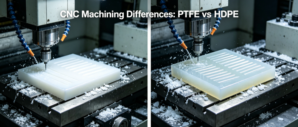
PTFE (Teflon) and HDPE are both soft, chemically resistant plastics. On the surface, they look like they can be machined with the exact same CNC settings.
If you run identical feeds, speeds and fixturing on both materials, you will run into two totally different nightmares.
PTFE stretches, creeps and slowly shrinks long after the cut finishes. Thin walls bend out of tolerance overnight.
HDPE melts easily, creates endless stringy chips, and leaves sticky smeared edges all over your finished part.
Most job shops mix up their process settings and waste hours fixing burrs, deformation and thermal drift.
At Zorapid, we machine thousands of PTFE sealing parts and HDPE wear components for chemical, semiconductor and automation clients across Europe and North America.
We have separated the unique machining rules for these two plastics completely.
Today we break down every critical difference: material behavior, tooling, cutting parameters, fixturing and common defects. Every tip comes directly from our daily milling and turning production.
Core Material Behavior: The Root Of All Machining Differences
First, we need to understand why these two plastics react so differently under cutting force.
PTFE Key Trait: Extreme Ductility + Cold Creep
- Elongation can reach 400%. Instead of shearing cleanly, PTFE stretches ahead of the cutting edge.
- Severe cold flow (creep). Even after you finish machining, internal stress slowly makes the part shrink or bend over 24–72 hours.
- High thermal expansion. Small temperature changes shift dimensions noticeably.
- Low friction prevents chips from sticking, but the material gets squeezed out of shape under heavy clamping pressure.
HDPE Key Trait: Low Melting Point + Tough, Stringy Structure
- Melts quickly at 130°C. Even mild frictional heat turns solid plastic into sticky molten flash.
- High toughness creates continuous long string chips instead of broken small pieces. These chips wrap around the cutting tool and re-weld onto part edges.
- No creep after machining. Once HDPE cools fully, it holds shape steadily. The only error comes from heat melting during cutting.
- It resists stretching but deforms when heated, so thin sections warp only from hot cutting zones.
Biggest difference in one sentence:
PTFE fails from mechanical stress and delayed creep deformation.
HDPE fails from thermal melting and tangled string chips.
Tool Geometry & Tool Selection
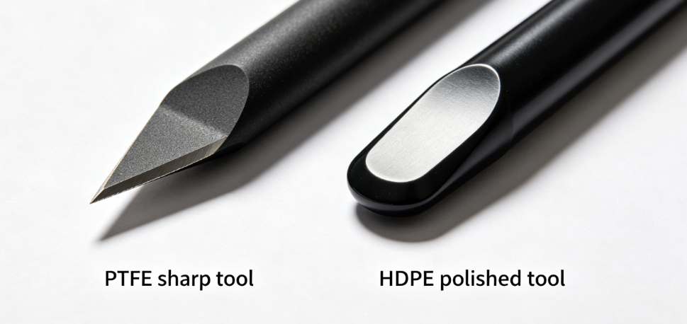
Both materials need razor-sharp positive-rake tools, but the edge finish and angles cannot be copied one-to-one.
PTFE Tool Standard
- Rake angle: +15° ~ +20° high positive rake to lift and shear stretched material, never plow it.
- Zero edge hone. Even a tiny rounded edge will tear PTFE into fuzzy whisker burrs.
- Polished flute surfaces. No coating needed; uncoated fine-grain carbide works best. Coatings create extra friction.
- Small nose radius for finishing, to reduce compression on soft plastic.
HDPE Tool Standard
- Rake angle: +10° ~ +15° positive rake. Too steep a rake digs into the tough material and creates chatter.
- Sharp edge, but slight micro-honing is allowed to prevent edge chipping on continuous string cutting.
- Super polished flutes to stop long HDPE chips from welding onto the tool surface.
- Slightly larger nose radius to smooth over melted edge smearing.
Critical Mistake We See Every Day
Using PTFE ultra-sharp zero-hone tools on HDPE causes edge chipping.
Using HDPE slightly rounded inserts on PTFE immediately creates stretched burrs.
Feeds & Speeds — Heat vs Mechanical Shear
The core logic is reversed for these two plastics.
- PTFE: Limit cutting force, control mechanical stretching.
- HDPE: Eliminate rubbing friction, stop material from melting.
PTFE CNC Milling & Turning Settings
- Spindle SFM: 250 ~ 450 (moderate speed, avoid high RPM heat buildup)
- Feed rate: Medium chip load. Fast enough to shear chips, slow enough not to squeeze the part out of shape.
- Light depth of cut: 0.10 ~ 0.25mm finishing passes only. Heavy cuts lock in residual stress and trigger creep deformation days later.
- No aggressive high-feed toolpaths. Keep cutting force low at all times.
HDPE CNC Milling & Turning Settings
- Spindle SFM: 600 ~ 900 (run much higher RPM)
- Feed rate: Aggressively high feed to move the tool quickly, so it never rubs in one spot long enough to melt plastic.
- Moderate depth of cut. You can remove material fast as long as you keep the tool moving nonstop.
- Rule for HDPE: Fast RPM + fast feed = no melting. Slow feed = hot friction + welded string burrs.
Cooling Strategy (Total Opposite Approach)
- PTFE: Compressed air blast only. Flood coolant creates thermal shock and worsens post-machining shrinkage.
- HDPE: Mist cooling or air blast. Never flood with liquid water. Trapped heat melts inner layers while the surface cools, causing uneven warpage.
Fixturing & Clamping
This is where most shops mess up PTFE and HDPE production.
PTFE Fixturing Rules (Anti-Creep Control)
- Never use hard jaw heavy clamping. Over-tightening squeezes PTFE permanently. The part will spring out of shape after you release the chuck.
- First choice: Vacuum table fixture with full-area support. Distribute clamping pressure evenly across the entire plate.
- If you must use jaws, line them with soft foam padding and use only minimal torque.
- Machine thin-walled PTFE features last. Keep the blank thick and rigid for most of the cutting cycle to avoid bending.
- Always release clamps after roughing, let the part relax freely before finishing to release locked compression stress.
HDPE Fixturing Rules (Anti-Heat Deformation)
- HDPE does not creep under pressure, so firm clamping is acceptable. You do not need to worry about squeezing permanent deformation.
- Use padded aluminum soft jaws to avoid jaw indentations on the smooth plastic surface.
- Add full back support blocks under the part to stop thin panels from lifting and vibrating during high-speed cutting.
- No need to release clamps between rough and finish. HDPE only distorts from heat, not mechanical compression.
Machining Sequence & Post-Process Stabilization
PTFE Strict Multi-Stage Process (Fight Creep Shrinkage)
- Rough mill, leave 0.25~0.35mm uniform stock on all surfaces.
- Loosen all fixtures, let the part sit freely at 20°C room temperature for 4~6 hours to release compression stress.
- Re-clamp lightly, run ultra-light finishing passes with low cutting force.
- After machining completes, store the part in a constant-temperature environment for 24~48 hours before CMM inspection. Most PTFE dimensional drift only appears one full day after cutting. You must wait for creep to finish before measuring final dimensions.
HDPE Simplified Single-Stage Process (Fight Melting Only)
- Rough and finish in one continuous cycle if possible.
- Split long toolpaths into short segments to let the part cool between cuts.
- Once HDPE fully cools down to ambient temperature, its size stops changing completely. No waiting period is needed. You can inspect and ship HDPE parts right after cooling.
Common Defect Sets
We split typical failures clearly for quick shop troubleshooting:
PTFE Typical Defects
- Delayed bending & shrinkage 1–3 days after machining (cold creep from clamping stress)
- Fine whisker burrs caused by material stretching instead of clean shearing
- Thin wall collapse from heavy cutting pressure
- Hole size slowly shrinks after the part leaves the machine
HDPE Typical Defects
- Long stringy chips wrapped around tools, re-fusing onto edges into sticky flash
- Local melted depressions where the tool pauses too long
- Edge smearing and rounded corners from molten plastic flow
- Thin panels warp from uneven hot spots during high-speed milling
| Feature | PTFE (Teflon) | HDPE |
|---|---|---|
| Main failure cause | Mechanical stress + cold creep | Frictional heat + melting |
| Burr type | Stretched whisker tears | Melted sticky flash |
| Clamping limit | Very low pressure, vacuum fixture | Firm padded clamping allowed |
| Cutting speed | Moderate RPM, low feed load | High RPM + aggressive fast feed |
| Post-machining shift | Slow shrinkage over 48 hours | Zero shift once fully cooled |
| Thin-wall risk | Squeezed bending | Heat warping only |
| Chip shape | Short broken chips | Continuous long string chips |
Zorapid Standard Process SOP For Each Material
PTFE Burr & Deformation-Free Workflow
- Pre-relieve blank stress with low-temperature annealing
- Mount on full vacuum table, no hard jaw clamping
- Rough cut with light passes, leave 0.3mm stock
- Unclamp and free-relax 6 hours at constant temperature
- High positive-rake sharp tool + air cooling only
- Ultra-light finishing cuts, low cutting force
- Let part stabilize 48 hours before dimension inspection
HDPE Chip & Melt-Free Workflow
- Clamp firmly with padded soft jaws and full back support
- High spindle RPM + fast feed to avoid tool rubbing
- Split long milling paths into short segments with cooling pauses
- Polished positive-rake carbide tool to stop chip welding
- Air or mist cooling only, no flood liquid
- Inspect right after the part cools to room temperature
Measurable Production Result:
- PTFE process: Creep deformation controlled below 0.008mm; zero delayed shrinkage
- HDPE process: Zero melted edge flash; no tangled string chips wrapping cutting tools
Real EU Client Case Study
A Dutch chemical equipment manufacturer ordered two batches: PTFE sealing gaskets and HDPE guide wear strips.
They ran the exact same CNC program and tooling on both materials with poor results:
- PTFE gaskets deformed 0.03mm after 2 days due to over-clamping and unreleased compression stress
- HDPE strips were covered in melted string burrs from low feed and slow spindle speed
We separated the two processes fully:
- For PTFE: Switched to vacuum fixturing, added free relaxation time between roughing and finishing, used zero-hone high-positive-rake inserts
- For HDPE: Raised spindle RPM, doubled feed rate, added polished flute tools to break string chips and prevent melting
Final outcome:
PTFE gaskets held stable dimensions with no post-machining creep.
HDPE wear strips had crisp clean edges with zero molten flash, no secondary deburring required.
Conclusion
PTFE and HDPE may both be slippery corrosion-resistant plastics, but their CNC machining rules are almost opposite.
- PTFE is sensitive to pressure and time. You fight creep, stretching and delayed shrinkage with low clamping force, light cuts and long stabilization waiting periods.
- HDPE is sensitive only to heat. You avoid melting and stringy chips with high spindle speed, fast feed rates and polished cutting tools.
Never copy your PTFE parameters directly onto HDPE jobs, or vice versa.
At Zorapid, we run separate toolpaths, fixturing and cutting schedules for Teflon and HDPE precision plastic components for chemical processing, semiconductor and automation OEMs across Europe and North America.
If you keep mixing up processes and fighting deformation or edge defects, send your part drawings. Our CNC process team will build separate optimized machining plans for PTFE and HDPE with zero extra scrap.
FAQ
Can I use the same carbide inserts for PTFE and HDPE?
Only if you re-hone the cutting edge. PTFE requires a completely sharp zero-edge radius. HDPE needs a tiny micro-hone to prevent edge chipping on continuous string cutting. We keep separate tool sets to avoid rework.
Why can’t I use flood coolant on PTFE parts?
Liquid flood creates uneven thermal expansion. PTFE’s high expansion rate causes uneven shrinkage after cooling, making tight tolerance impossible. Dry compressed air blasting works best.
Does HDPE have cold flow creep like PTFE?
No. HDPE holds its shape perfectly once it cools down. All dimensional errors only happen while the part is hot during cutting. You never need long stabilization waiting periods for HDPE parts.
How do I stop PTFE thin walls from bending after machining?
Machine all thick bulk material first, finish thin ribs as the last operation. Always release clamps after roughing to let trapped compression stress escape before finishing. Vacuum full-area support is far better than side jaw clamping.