The manufacturing industry is further upgrading with the continuous development of economy and technology.Zorapid CNC Machining starts with an introduction to the development history of CNC milling and mold processing, as well as the characteristics of molds. Meanwhile, it expounds targeted optimization solutions from three dimensions: basic processing technology, cutting tools, and mold parts.
Zorapid CNC Machining is able to provide professional CNC machining solutions and serve as a reliable reference for your processing projects.Currently, the manufacturing industry is undergoing transformation. Machine tools are widely adopted in mechanical processing.
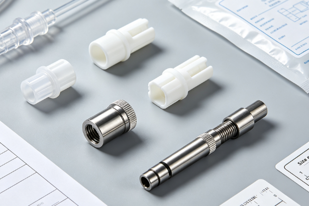
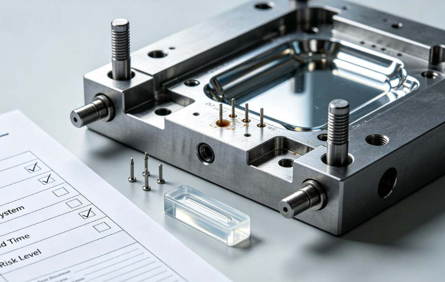
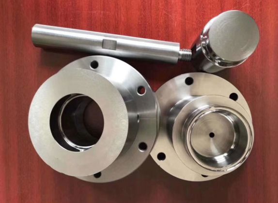
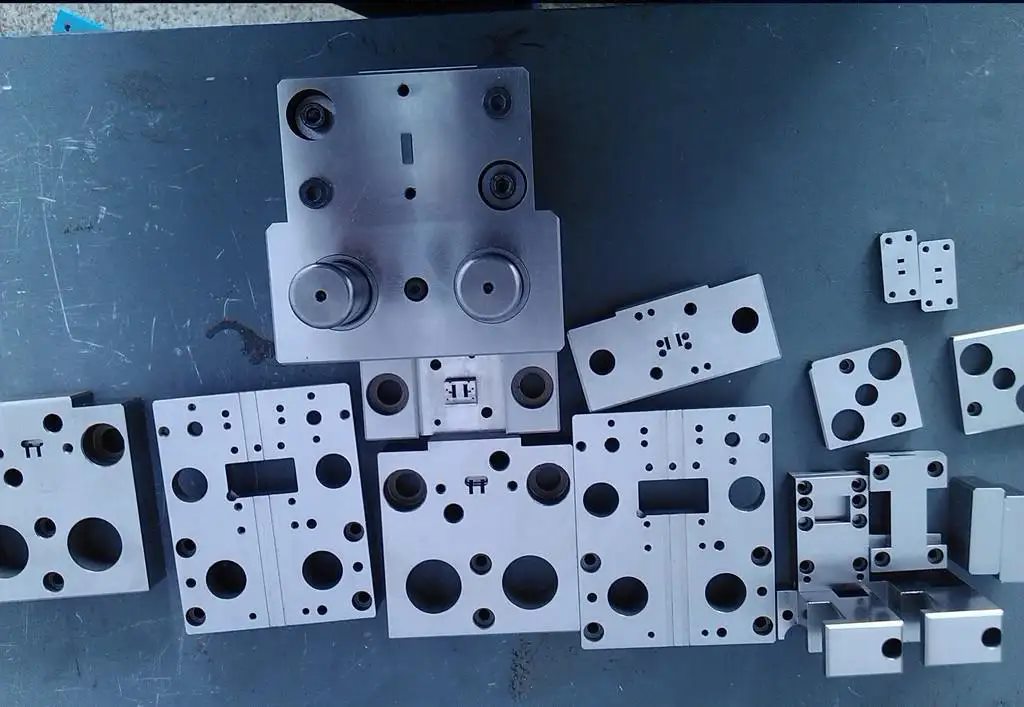
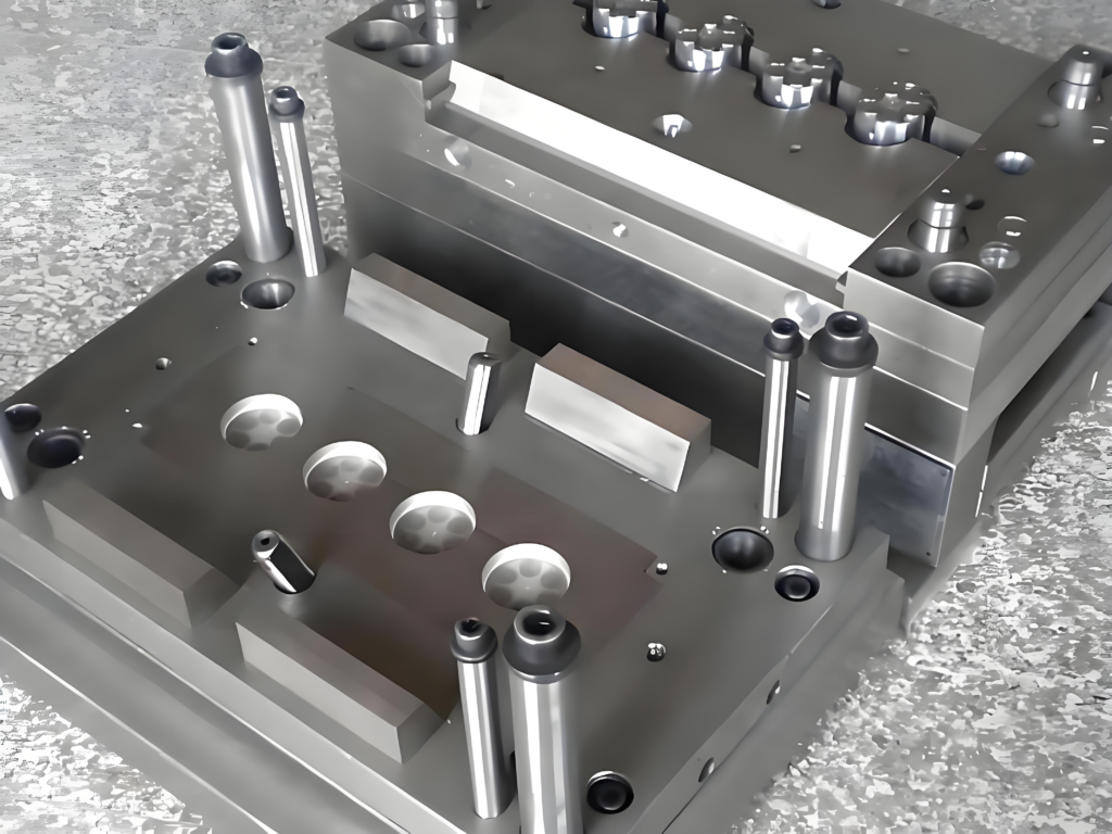
CNC machining units are the core of the modern mechanical processing industry, and molds are the key components of CNC machining. The design and quality of molds are closely related to the development of the processing industry.
The Development of CNC Technology
With the rapid advancement of economy and science and technology, people’s daily needs have become increasingly diversified, and requirements for daily necessities and other products keep rising. This has accelerated the upgrading and iteration of modern products and boosted small-batch production orders for manufacturing enterprises.
The production efficiency of light industry continues to grow, and the consumption rate of daily supplies remains high, which also demands higher precision for molds.Yet related mold design and production still face major issues, seriously hindering mold manufacturing and application and requiring urgent resolution.
Characteristics of CNC Milling Technology
Highly capable
CNC milling delivers robust complex machining, widely used in aerospace and marine manufacturing.Machining quality is closely related to the overall quality and performance of products. This technology can accomplish complex machining tasks that conventional standard processing methods cannot achieve.
Excellent Quality
As a digital technology, CNC milling can complete automatic machining operations under program control, effectively avoiding machining errors and other issues caused by human factors.
In addition, if parameter errors occur during processing, the CNC system can automatically perform correction and compensation to ensure smooth machining progress.
High Efficiency
Compared with traditional mold part processing methods, CNC milling delivers much higher efficiency in mold component manufacturing.
Especially for pentahedral parts and flexible unit parts, it can finish machining of most positions in one setup.
It greatly reduces the error rate caused by repeated clamping and processing, while significantly improving production speed.
Good Flexibility
Its great flexibility lies primarily in machining diverse parts and molds.It only requires adjusting the preset program to machine various types of components, eliminating the need to customize dedicated fixtures.
This greatly shortens the production and processing cycle, making it perfectly suitable for small-batch custom part production in modern manufacturing.
Basic Process of Zorapid Optimized CNC Programming for Molds
In the machining of mold parts, CNC milling operations are performed on CNC machine tools. It is essential to control the CNC programming process to guarantee machining quality. The whole workflow consists of four stages: preparation, planning, programming, and final confirmation.
Preparation Stage
Before part machining, adequate preliminary work must be completed. Programmers carefully review and analyze relevant technical data, then formulate and compile the CNC machining program in advance.
Planning Stage
After finishing the preparation work, programmers formulate the production procedures for parts and molds based on the workshop’s available resources, cutting tools, machine tools, equipment and actual production capacity.
Programming Stage
This is the most critical step in the entire workflow. During programming, engineers design machining methods and process routes according to the structural characteristics of parts.
It is also necessary to comprehensively evaluate machine tool and workshop conditions, select suitable fixtures and auxiliary components. Under the confirmed process scheme, the corresponding tool motion paths are calculated with computer assistance.
Simulation software is then used for verification and toolpath optimization to guarantee CNC program accuracy.
Final Confirmation Stage
This is the final and acceptance phase of CNC process programming. CLS format and PRT format files are the most commonly used program formats at this stage.
Zorapid Optimized CNC Cutting Tools for Molds
Cutting tools play a vital role in the machining of mold parts. To ensure superior machining quality, tool optimization is essential. The optimization is carried out from two key aspects:
First, reasonably select the type and specification of cutting tools.
Cutting tools are widely used in CNC milling, mainly for machining the forming surfaces of molds. The most commonly used tools include ball end mills and flat end mills. Tool specifications are generally selected according to the required quality of mold parts.
Second, properly choose tool materials.
Tool material should be chosen based on workpiece material and cutting requirements, avoiding waste from rigid tools with underutilized cutting performance.
For complex, high-hardness parts, high-speed steel tools are ideal for reliable wear resistance, cutting speed and structural strength.
Optimization of Zorapid Mold CNC Parts
Optimize Machining Method
In the machining of mold parts, it is essential to ensure the cutting tool runs smoothly on inclined surfaces without sudden changes in motion trajectory. Maintain a stable cutting speed when machining inclined planes, arcs and other complex profiles.
When the cutter comes into contact with the inclined surface of the part, friction is generated, which easily causes resonance. It is necessary to reasonably control the cutting length and angle to effectively reduce resonance vibration.
Optimize Cutting Parameters
In CNC milling operations, cutting parameters are closely related to the overall quality of mold parts. It is required to properly adjust cutting depth and feeding speed to ensure smooth surface finish and qualified machining quality.
Cutting allowance is set based on workpiece rigidity, aligning actual machining depth with design depth. This cuts redundant tool passes and boosts overall machining quality.
Optimize Inner Inclination Machining
The cutting strategy needs to be optimized when milling inner inclined surfaces of mold parts. The traditional vertical cutting method requires a significant reduction in cutting speed, and often results in rough part surfaces as well as severe tool wear.
Adopting the helical feed machining method can achieve superior cutting performance, with reasonable control of the tool path radius as a key technical point.
Case Study of CNC Milling
Large machining error has long been a difficult problem in CNC milling of mold parts. Based on process analysis of this issue, this paper elaborates on key points and corresponding solutions in the CNC milling process of mold parts. The proposed method improves machining efficiency while ensuring the surface roughness and dimensional accuracy of mold parts.
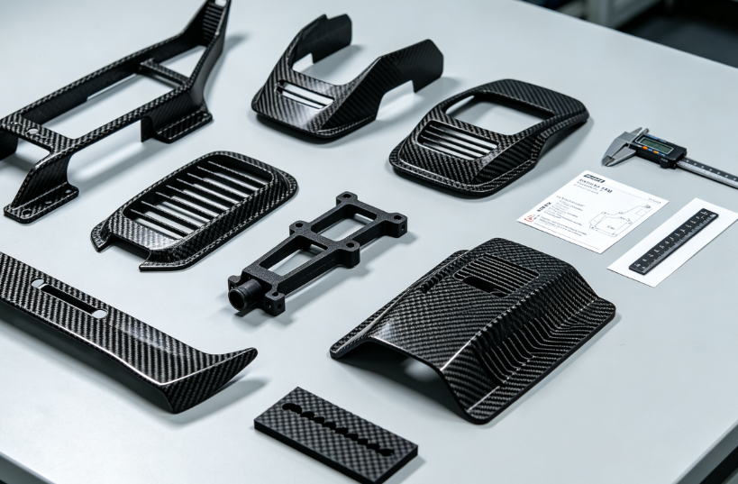
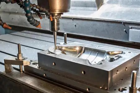
China’s mechanical processing industry is in a stage of rapid development, and CNC machine tools are now widely used in various fields, including molds, automotive, aviation, aerospace, general machinery, electronics, and home appliances. CNC machine tools effectively solve the machining difficulties of complex-shaped parts, realize processing automation, greatly boost production efficiency, and reduce manufacturing costs. Nevertheless, some technical challenges still remain in actual CNC machining.
The mold part features inclined surfaces. The machine tool adopted is XK7132, and the workpiece material is 2A12 aluminum alloy.
Cutting parameters: spindle speed \(n=1500\,\text{r/min}\), feed rate \(f=200\,\text{mm/min}\), end mill diameter Φ14 mm.
The dimensional accuracy of the part is affected by the machine tool, cutting tool and machining program. After machining measurement, the actual inclined angle is \(60^\circ20’\), which shows a large deviation compared with the design requirement of \(60^\circ\pm4’\). The surface roughness of the inclined surface is also unsatisfactory, measured at Ra 12.5 μm. Obvious tool marks appear on the arc transition between the two inclined surfaces. Repeated verification confirms that workpiece positioning, machining procedures and equipment accuracy are all normal, yet the above defects still cannot be eliminated.
Therefore, Zorapid CNC Machining conducts an in-depth analysis on the key operational guidelines in actual production, as well as effective measures to improve machining accuracy and guarantee qualified surface roughness.
Machining Process Analysis
By selecting different end mills, this paper compares the contact state between the cutter and the inclined surface of the workpiece during machining, and further explores the CNC milling method for inclined surface parts through comparative analysis.
Machining Method of Chamfered End Mill
Cutting parameters: spindle speed 1200 r/min; feed rate 100 mm/min; flat end mill diameter Φ14 mm; tool tip chamfer β=30°.
As shown in Figure 2, besides the ABC profile in the diagram, there are obvious residual sections AHG and CEF formed by mold material allowance. The residual area on the part surface increases noticeably. The distance between the ideal curved surface and valley G is GJ. Machining takes points E and G as reference benchmarks; nevertheless, a dimensional deviation of GJ still remains between the ideal curved surface and the actual machined surface, with excess material left between E and G, resulting in large dimensional errors of the finished workpiece.
Subsequent machining lacks effective reference datums under this condition, making it difficult to produce parts that meet the designed dimensional requirements.
Non-chamfered End Milling Method
Cutting parameters: spindle speed 1200 r/min; feed rate 100 mm/min; end mill diameter Φ14 mm; tool nose radius R=0.
To better analyze machining accuracy, cutter contact with the inclined surface is ideally modeled in Figure 3. Between adjacent tool passes, the height difference BD between peak B and valley A equals the residual material on the machined face. For ABC-style parts, finish machining removes this leftover material to meet dimensional requirements.
Reducing the machining increment in parameter settings can lower the BD value, decrease surface residual allowance and ease machining difficulty. However, this approach will add more machining cycles in actual production, extend processing time and reduce overall working efficiency.
The non-chamfered end milling method is only theoretically feasible. In practical machining, the tool chamfer cannot be zero. Without tip chamfering, the strength and rigidity of the end mill will decline, easily causing tool wear and edge chipping during cutting, and resulting in unsatisfactory surface roughness of finished parts. Therefore, non-chamfered milling cutters are not adopted in actual production.
Process Solution
Improve Machining Quality with Chamfered End Mills
The above analysis shows that non-chamfered end mills could theoretically deliver optimal machining quality. To obtain an ideal inclined surface, it only requires removing tool marks on the surface after milling. However, this method causes severe tool wear and even generates problematic chips. For this reason, non-chamfered end mills are generally not used in practical machining. There are multiple effective ways to adopt chamfered end mills to improve machining quality, and guarantee dimensional accuracy and surface finish.
Optimize Machining Method
During machining:
Keep the tool moving steadily along the inclined surface and avoid sudden changes in cutting direction. Reduce the milling feed rate when cutting arcs between inclined planes.
When the cutter first makes contact with the part’s inclined surface, the flank face generates considerable friction against the workpiece, which easily induces tool resonance.
As the cutter moves into inclined surface arc transitions, both cutting angle and milling engagement length rise. In climb milling, thin cutting thickness causes cutter elastic deflection. In conventional milling, force behavior reverses; cutter elastic deformation induces resonance and leads to over-cutting.
Selection of Cutting Parameters
Cutting parameter selection is critical in mold machining. Properly chosen parameters directly determine the final machining quality. Reasonable matching of cutting depth and feed speed ensures an ideal surface finish.
For cutting parameter configuration, within the allowable rigidity range, set the cutting depth equal to the finished machining depth. This effectively reduces the number of tool passes and improves overall processing efficiency.
Reasonable Toolpath Configuration
When planning the milling toolpath, it is necessary to guarantee the machining accuracy and surface roughness of parts, while minimizing cutting passes and idle travel paths.
Use properly radiused arc transitions between adjacent tool paths on part inclined surfaces. Programming fixed-radius arc transitions eliminates sharp directional changes, enabling smooth, continuous cutter movement to the next machining path.Use suitable radius arc transitions for equal-height inclined mold surfaces.
Adopting arc transitions between the two structural layers of the mold not only realizes smooth toolpath operation, but also significantly reduces the cutting resistance of helical plunging and lowers tool wear.
With arc transition setting, the cutter can approach and retract along the tangential direction of the part profile, which effectively improves the overall machining quality.
When machining inclined mold surfaces
Avoid vertical cutting; use helical feed instead. Vertical plunging reduces cutting speed and raises cutter-to-mold cutting force, speeding tool wear and ruining surface finish. Helical feed effectively eliminates these issues.
When cutting parts with helical feed, a reasonable range of helix diameter should be set. If the helix diameter is smaller than the preset range, the system will automatically reduce the helix diameter until normal cutting is achievable.
Do not set the helix diameter too small. An overly small helix diameter acts like vertical cutting, where ramp cutting is the better alternative.
The number of ramp cutting passes should be properly controlled during machining. Repeated inclined cutting will generate severe vibration, leaving obvious tool marks on the machined surface. In severe cases, it will cause excessive tool wear or even tool breakage.
Curved mold surfaces require a well-chosen machining strategy. In finishing, overly narrow toolpath spacing results in tiny transition arcs that act nearly straight, even with arc blending. Moderately widening toolpath spacing ensures consistent machining quality.
Flexible Application of CNC Milling Technology in Zorapid CNC Machining
We analyzed large dimensional errors in CNC machining of angled mold components.Obvious tool marks and poor surface roughness often occur at arc transitions between adjacent inclined surfaces.This paper analyzes the machining process and offers practical solutions plus key on-site operating precautions.
Standardize the process by selecting properly sized chamfer end mills, using climb milling, designing suitable radii for arc transitions between inclined surfaces, and adopting helical plunge cutting. This approach greatly boosts machining accuracy while ensuring excellent surface finish.
Practical production verification shows that this method can significantly enhance dimensional accuracy, reduce surface roughness, raise production efficiency and lower manufacturing costs. It is worthy of wide promotion and application in actual production.
This paper analyzes the application and technical features of CNC milling for mold parts at Zorapid, and puts forward targeted optimization measures. It aims to upgrade overall milling performance, guarantee part quality, control production costs, and deliver greater economic benefits for manufacturers.
FAQ
What are the common problems in CNC milling of mold parts?
Common issues include severe tool wear, poor surface precision of curved surfaces, obvious tool joint marks, machining deformation, uneven allowance after heat treatment, incomplete corner cleaning of cavities, and low processing efficiency.
What aspects can be improved for mold CNC milling process?
Optimization covers eight key areas: tool selection, process routing, cutting parameters, clamping method, toolpath optimization, separate roughing and finishing, coordinated heat treatment, and machine-fixture matching.
How to improve mold milling quality by optimizing tool path?
Adopt layered contour milling and spiral tool paths to reduce idle travel; apply corner deceleration and arc transition to minimize vibration lines and tool marks, and improve surface finish of mold cavities.
How to reduce machining deformation of mold parts?
Separate roughing and finishing properly, and release stress by aging after roughing; adopt symmetrical and layered cutting; optimize clamping points to avoid local stress deformation; use qualified blanks and reserve uniform machining allowance.
What benefits can optimized CNC milling process bring?
It improves dimensional accuracy and surface quality, reduces polishing time and tool consumption, shortens production cycle, lowers scrap rate, and adapts to mass production of precision molds.