Publisher: Zorapid.Ltd
More than 75% of CNC part cost is locked in the CAD drawing, long before the first cutting tool touches raw material.
You finish your 3D model, run performance simulation, and send files out for quotation.
Then the price comes in far higher than your budget.
The workshop has to run slow low-speed cuts, swap fragile small tools repeatedly, build multiple custom fixtures, and spend hours on strict dimensional inspection.
Every small design oversight adds cycle time, scrap risk, labor cost and tooling expense.
At Zorapid, we run free DFM reviews for thousands of precision CNC orders every month for aerospace, medical and automation OEMs across Europe and North America.
We repeatedly see the same 8 design errors pushing CNC cost 25~40% higher with zero improvement to part performance.
Blanket Over-Tolerancing Across The Entire Part
What engineers do wrong
Designers often apply tight ±0.005mm tolerance on every dimension, including cosmetic outer edges, unused cutouts and non-mating surfaces.
They assume tighter dimensions equal better quality.
Real production cost impact
Tight tolerances force the machine to slow down, split extra finishing passes, run temperature-controlled inspection, and reject parts easily from tiny drift.
A full drawing with universal precision can raise total machining cost by 35% or more.
Only 5~10% of all dimensions actually require tight fit for assembly. The rest work perfectly with standard loose tolerance.
Low-Cost DFM Fix
- Keep strict GD&T tolerance only on locating holes, sealing faces and mating shut-off surfaces.
- Set general default tolerance (±0.12~±0.25mm) on all free edges, pockets and cosmetic features.
- Never apply micron-level tolerance on surfaces that do not touch other components.
Sharp Zero-Radius Internal Corners
Common design flaw
Square sharp inner corners with no fillet radius.
Ball end mills cannot reach perfectly sharp corners. The shop has to switch to tiny micro tools to clean out leftover stock.
Cost penalty
Small-diameter tools run at very low feed rates, wear out fast, and create long extra toolpath time.
Deep square pockets can double total milling cycle time, plus you pay for frequent tool replacement.
Simple CAD Correction
Add a minimum standard radius matching your common tool size (R0.8, R1.5, R2.0) to all internal corners.
The workshop uses standard-size end mills at full cutting speed, with no rest-milling cleanup required.
The part strength stays unchanged, while machining runtime drops sharply.
Deep Narrow Pockets With Extreme Depth-To-Width Ratio
The costly geometry
Long, narrow deep cavities where pocket depth exceeds 4× the internal width.
Machinists have to use extra-long extended tool holders to reach the bottom.
Production trouble
Long slender tools vibrate severely, create chatter waves, bend easily and risk breakage.
Operators must reduce cutting speed drastically to avoid tool failure, which stretches machining time significantly.
Thin pocket walls also deform under cutting force, pushing up scrap rates.
DFM Optimization Rule
- Limit pocket depth ≤ 3× the pocket width wherever possible.
- Widen narrow slot openings slightly to allow short, rigid standard tools.
- Split one deep single pocket into two shallower cavities if design space allows.
Unreasonably Thin Walls & Unreinforced Slim Ribs
Poor geometry choice
Wall thickness thinner than 0.6mm on steel parts or 1.0mm on aluminum, with no supporting ribs.
Thin sections have almost no rigidity during high-speed milling.
Extra cost generated
The thin web vibrates continuously while cutting. Operators must split dozens of light finishing passes instead of fast bulk material removal.
Walls bend out of flatness after clamping release, leading to high scrap from dimensional instability.
Thin ribs also require secondary hand sanding to remove chatter marks, adding bench labor hours.
Standard Wall Thickness Rule
- Steel alloy minimum wall: ≥ 0.8mm
- Aluminum minimum wall: ≥ 0.7mm
- Engineering plastic minimum wall: ≥1.5mm Add small reinforcing ribs on long thin sections to boost rigidity and allow faster stable cutting.
Multi-Angle Features Requiring 4~6 Separate Fixture Setups
Design problem
Features spread across 5 or 6 different faces with no unified datum plane.
Every new side needs the operator to tear down the fixture, re-align, re-edge-find and reset zero positions.
Hidden cost waste
Machine spindles sit idle during repeated clamping changes. Setup labor becomes a major portion of the total job cost.
Every re-clamp also introduces small cumulative positioning error, raising rework and rejection risk.
If you need custom angle jigs for inclined holes, fixture cost jumps even higher.
Cost-Saving Design Revision
- Rearrange part geometry so most critical features sit on 2~3 main orientations.
- Consolidate angled holes to fit within 3+2 axis 5-axis single-setup work, eliminating repeated re-fixturing.
- Design a unified primary datum face so the whole part can be clamped once on zero-point pallets.
Non-Standard Hole Sizes, Odd Depths & Excessively Long Tapped Threads
Frequent engineering oversight
Random decimal hole diameters, custom odd tap sizes, and full-depth blind threads running all the way to the pocket bottom.
Cost breakdown
Standard drill bits and taps cover all common metric sizes. Odd custom sizes force the shop to use slow laser piercing or order special custom tooling with long lead time.
Blind full-depth taps easily jam and break inside deep holes, creating expensive rework on finished components.
DFM Standardization Rules
- Stick to standard drill sizes: 3mm, 4mm, 5mm, 6mm, 8mm, 10mm. Avoid 4.7mm or 7.3mm random sizes.
- Leave 1.5× thread diameter empty clearance at the bottom of blind tapped holes to prevent tap breakage.
- Shorten thread length only to the actual engagement length required for assembly. Extra thread depth wastes tap machining time.
Undercut Recesses Blocking Standard Tool Paths
Design mistake
Internal undercuts, backside hidden pockets and blocked cavities that standard straight tools cannot reach.
Consequence
The workshop must switch to costly small diameter boring bars, form tools or 5-axis simultaneous milling just to clear small recesses.
3-axis machines cannot reach these zones at all, forcing an expensive upgrade to 5-axis machine time with higher hourly rates.
Simple Improvement
Simplify undercut geometry into open-sided pockets where possible.
If undercuts are mandatory, design them with standard tool reach in mind to avoid special custom tooling.
Over-Complicated Unnecessary Geometry & Extra Cosmetic Features
Common over-design
Extra decorative grooves, fine engraved patterns, complex curved contours that serve no mechanical function.
Each extra feature adds new toolpaths, extra program lines and extra cutting cycles.
Every small engraved slot adds 5~15 minutes of machine runtime on batch production.
Cosmetic details do nothing for part performance but push up CNC cycle time significantly.
DFM Principle
Cut every feature that does not support fit, strength or sealing.
Keep geometry prismatic wherever you can; simple straight pockets cost far less than blended free-form curves.
Cost Comparison Table: Bad Design vs DFM Optimized Design
| Design Issue | Extra Cost Increase | CAD Fix |
|---|---|---|
| Full-part blanket tight tolerance | +30~40% | Tight tolerance only on mating features |
| Sharp zero-radius inner corners | +22~35% | Add standard R fillets on all inner edges |
| Deep narrow high ratio pockets | +25~50% | Widen slots & limit depth under 3× width |
| Ultra-thin unsupported walls | +20~38% | Raise wall thickness to minimum rigid value |
| 5+ repeated fixture setups | +28~45% | Consolidate features into 1~2 clamping orientations |
| Non-standard custom hole sizes | +15~25% | Use off-the-shelf standard drill & tap sizes |
| Unreachable undercut recesses | +40~100% | Open pockets for standard tool access |
| Extra cosmetic non-functional features | +12~20% | Remove all unnecessary grooves & engravings |
Zorapid Standard Pre-Order DFM Checklist
Run this check before releasing your STEP file for quotation, and you will avoid most cost overruns:
- Audit all tolerances; relax non-critical dimensions to standard loose specs
- Add uniform corner radii and eliminate all sharp inner zero-radius corners
- Check pocket depth-to-width ratio; split deep narrow cavities into shallow sections
- Verify wall thickness meets rigid minimum value, add ribs on long thin webs
- Consolidate part orientations to minimize re-clamping setups
- Standardize all holes, bores and thread sizes to common tool dimensions
- Remove unreachable undercuts or simplify geometry for standard tool access
- Delete all decorative features with no engineering purpose
Real Measurable Result:
Unoptimized original drawing: 32% higher machining cost + longer lead time
After DFM revision with zero performance loss: Total cost reduced by 27%, scrap rate cut below 3%
Real EU Client Case Study
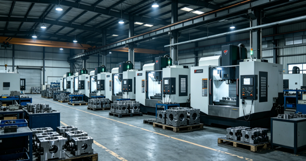
A Dutch industrial automation OEM sent us a complex aluminum manifold for CNC quoting.
The original design had three major costly flaws:
- Tight ±0.006mm tolerance applied across the entire manifold body
- Multiple sharp square inner corners requiring tiny small tool cleanup
- 5 separate clamping setups for multi-sided ports, with no unified datum
We revised the CAD strictly following DFM rules without changing fluid flow or assembly function:
- Restricted tight tolerance only to port sealing surfaces; relaxed all other dimensions
- Added standard R1.5 fillets on all inner corners to use standard end mills
- Rearranged port geometry to fit into a single 5-axis zero-point setup with no re-clamping
Final outcome:
Total CNC processing cost dropped by 29%, total lead time shortened by 3 working days, with zero impact on part function. The revised part passed all pressure testing and batch production smoothly.
Conclusion
High CNC machining cost rarely comes from high machine hourly rates or expensive raw material.
Most price inflation starts from small design errors made in the CAD phase.
Over-tolerancing, sharp corners, deep narrow pockets, thin walls, multi-setup geometry and non-standard features pile up extra cycle time, tooling expense, fixture labor and scrap risk.
You do not need to weaken part performance to save money. Simple DFM edits keep the exact same fit and function while cutting processing cost drastically.
At Zorapid, we provide free DFM design reviews for all CNC projects for medical, aerospace and automation OEMs across Europe and North America.
We spot costly geometry errors early, revise your 3D model, and lock in lower machining quotes before production starts.
If you keep receiving unexpectedly high CNC quotations, send your STEP and PDF drawings. Our DFM engineers will mark up all cost-driving flaws and deliver an optimized low-cost version with no change to your part design intent.
FAQ
Can I keep sharp inner corners if I use wire EDM later?
Wire EDM adds extra secondary operation cost. Adding small fillets still remains cheaper than splitting milling and EDM work into two separate processes. We recommend standard radii for most general CNC parts.
Does loosening non-critical tolerances affect part assembly quality?
No. Only mating locating surfaces need strict precision. Free outer edges and open pockets never touch other parts. Relaxing their tolerance only speeds up machining without hurting assembly performance.
Is 5-axis always cheaper than multiple 3-axis setups?
Single-setup 5-axis eliminates repeated fixture labor. For parts needing 4+ re-clamps, switching to one 5-axis clamping always lowers total cost, even with slightly higher machine hourly rates.
Why do thin walls push cost so high?
Thin sections vibrate and deflect. Machinists cannot run high-speed aggressive cuts. Every finishing pass has to be ultra-light, multiplying total milling time. Raising wall thickness just 0.2mm restores rigidity and allows full-speed stable cutting.