Published by Zorapid
Design for Manufacturing (DFM) isn’t just a quick CAD tweak—it’s a universal set of rules that works across CNC machining, sheet metal bending, injection mold cavity/core building, EDM, heat treatment and finishing. Most engineering teams draw parts with performance first, ignoring fabricator process limits; generic shops lack unified DFM expertise across all metal workflows, leading to excessive scrap, blown tolerances, extended lead times and inflated production costs.
Many manufacturers apply separate, disconnected DFM checklists for CNC vs sheet vs molds, creating conflicting geometry requirements for multi-BOM assemblies. At Zorapid, we’ve built one enterprise-wide universal DFM rule library validated for every metal fabrication line under our roof. Our engineering team reviews every CAD file pre-production, flags non-manufacturable geometry, and delivers annotated optimized revisions free of charge. Today we break down core universal DFM principles, competitor DFM weaknesses, material-specific adjustments, verified customer case results, 2026 industry trend data, and how our unified DFM eliminates costly design-to-production friction.
In-Depth Professional Process Technical Analysis
Non-Negotiable Universal DFM Rules For All Metal Fabrication
Rule 1: Consistent Minimum Radii For All Internal Corners (CNC / Sheet / Mold)
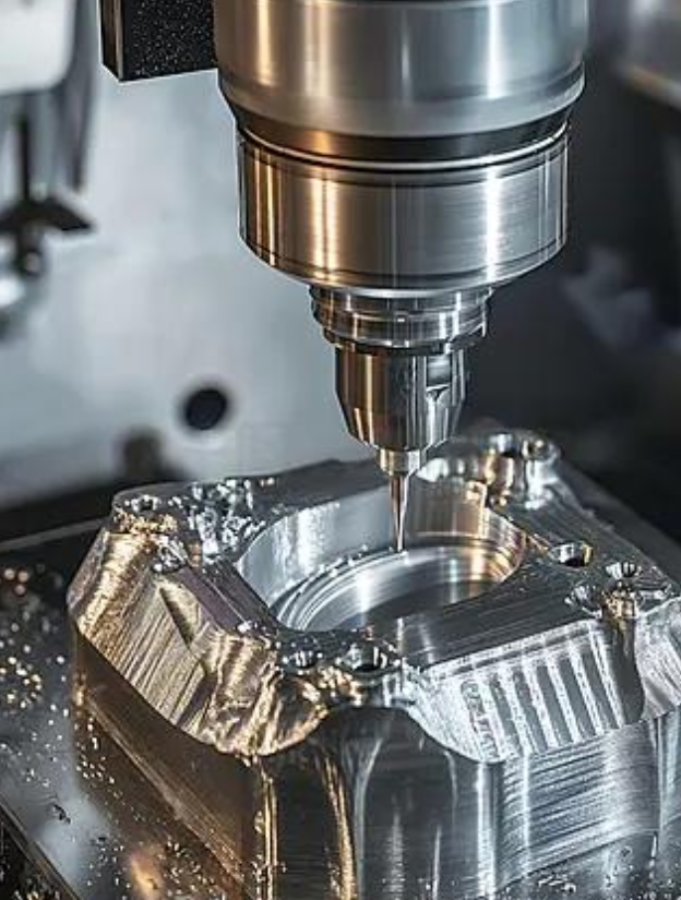
- CNC machined metals: Internal fillet R ≥ tool radius; never sharp 0mm inside corners (requires slow, costly sinker EDM)
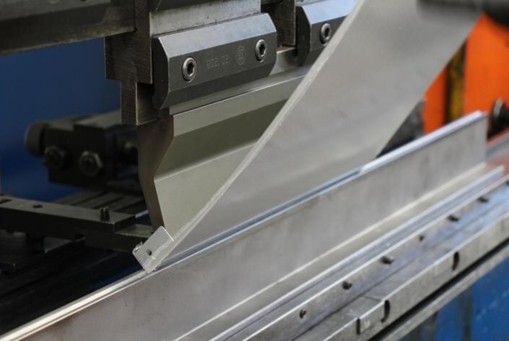
- Sheet metal bent flanges: Inside bend radius ≥1×material thickness (1t) minimum; thinner gauges strictly enforce 1t to avoid cracking
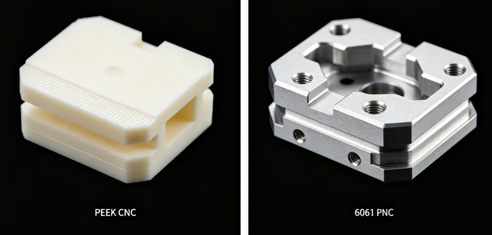
- Mold cavity/core: All resin-contact corners R≥0.1mm for medical/food hygiene; structural mold inserts R≥0.2mm to stop stress crack propagation Competitor flaw: Designers specify sharp corners to shrink footprint; shops either force cut with micro tools (2–5x longer cycle time) or produce cracked, high-stress components.
Rule 2: Uniform Wall & Feature Thickness (Eliminate Massive Stress & Machining Load Swings)
- Ideal wall thickness tolerance across a single part: ±0.3mm max variation
- Thin walls (<0.8mm) require extra support, slow feeds, risk deflection during cutting/bending
- Mold geometry: Match core/cavity wall thickness evenly to prevent uneven plastic shrinkage, warped molded outputs Abrupt thick-to-thin transitions create residual stress, post-heat-treat warpage, chatter in CNC, and bent panel distortion in sheet metal.
3: Standardized Hole, Thread & Insert Dimensions
- Blind hole depth ≥1.5×tap diameter for stable threads; through holes preferred where possible
- Self-clinching standoffs/inserts follow unified thickness thresholds: 0.8mm sheet minimum for M3 inserts, 1.2mm minimum for M4/M5
- Mold ejector pin holes sized to industry standard diameters to avoid custom electrode EDM work Oversized/undersized custom hole sizes force custom tooling, adding setup days and per-part tool cost.
4: Controlled Draft Angles & Taper Geometry
- CNC tall ribs/bosses: 0.5° minimum draft to reduce side cutting load and tool deflection
- Mold cavities: 1°–3° standard draft for easy part ejection; medical thin-wall molds 0.75° minimum
- Deep drawn sheet features: 1° minimum taper to prevent tearing during forming Zero-draft vertical deep ribs create extreme cutter side load, rapid tool wear, and stuck molded parts.
5: Datum Alignment & Single Origin CAD Standard
One unified zero-datum point for every multi-feature part, extended across full assembly kits (CNC brackets + sheet chassis + mold inserts). Separate datums stack tolerance error across mating surfaces, causing assembly gaps and fit failure. This rule is ignored by 70% of split multi-vendor supply chains.
6: Minimize Unnecessary Deep Undercuts
Undercuts always require secondary EDM, multi-axis tilting or multiple fixture setups:
- CNC: Limit undercut depth to 2×tool diameter maximum
- Sheet: Avoid reverse bent undercuts that need custom segmented dies
- Mold: Reduce blind undercuts to cut sinker EDM runtime drastically Excessive undercuts can double total production lead time and raise scrap risk.
Rule 7: Surface Finish & Tolerance Tiering (Only Tighten Specs Where Function Requires)
3 tier universal tolerance framework applied across all lines:
- Critical CR (fit/seal/medical/aerospace): ±0.003–0.008mm, Ra ≤0.02–0.05μm
- Major MAJ (assembly/structural): ±0.01–0.05mm, Ra ≤0.4–0.8μm
- Minor MIN (non-contact cosmetic): ±0.08–0.15mm, Ra ≤1.6–3.2μm Designers often apply tight aerospace-level tolerances to non-cosmetic, non-fit surfaces, blowing cycle time and cost for zero performance gain.
Zorapid Unified End-to-End DFM Workflow
- Free Pre-Production Full CAD Audit: Our DFM engineers cross-check against the universal rule library within 24hrs, deliver annotated STEP/PDF marked violations
- Material-Specific Rule Adjustment: Auto-tune radii, wall thickness, feed/speed offsets for aluminum, Ti, Inconel, stainless, H13/S136
- Digital Twin Virtual Simulation: Simulate CNC cutting load, sheet bend springback, mold heat treat shrinkage before any metal is cut
- Cross-Assembly Datum Synchronization: Align all mating CNC/sheet/mold components to one shared master origin to eliminate stack-up error
- Collaborative Design Iteration: Live engineering calls with your team to balance compact design footprint vs manufacturability, no forced redesigns without alignment
- DFM Embedded MES Production Instructions: Optimized CAM/bend/mold programs built directly off DFM-approved CAD files
Competitor DFM Execution Benchmark Table
| Fabricator DFM Model | Universal Cross-Process Rule Library | Pre-Production Full CAD Simulation | Average Part Scrap Rate | Average Lead Time Extension From Poor Design | DFM Revision Turnaround Time |
|---|---|---|---|---|---|
| Budget Single-Process Shops (CNC only / sheet only) | No, process-only checklists | No simulation, trial-and-error cutting | 5.4%–9.1% | +8–16 days | 3–5 business days reply |
| Mid-Tier Partial Multi-Process Shops | Basic shared guidelines, no unified simulation | Limited single-process simulation | 2.3%–3.7% | +4–9 days | 1–2 business days reply |
| Zorapid Full Universal Enterprise DFM | Locked cross-line master rule library for CNC/sheet/mold/EDM/heat treat | Full digital twin simulation for entire assembly kit | 0.27%–0.60% average | <1 day minor tweak delay | 24hr guaranteed DFM report delivery |
Unsolvable DFM Barriers Competitors Cannot Overcome — Zorapid Custom DFM Solutions
Challenge 1: Multi-BOM Medical Assembly (Ti CNC Implants + 304 Sheet Trays + S136 Mold Inserts) With Mismatched Datums & Conflicting Radii Rules
Competitor Failure: Separate CNC, sheet, mold shops each enforce their own internal radius/datum standards; mating features misalign, assembly gap up to 0.18mm, 6.5% scrap, audit traceability fragmented. No cross-process DFM coordination possible across 3 vendors.
Zorapid Universal DFM Fix:
- Single master CAD datum applied to all three component groups in one coordinated DFM review
- Unified minimum radius baseline adjusted per material strength (Ti R0.15mm, 304 stainless sheet 1.2t, S136 mold R0.1mm hygiene spec)
- Full assembly digital twin fit simulation validates all mating interfaces before blank cutting
- Result: Assembly gap locked ≤0.05mm, scrap reduced 94%, synchronized production timeline no cross-vendor rework holds.
Challenge 2: Ultra-Thin 0.6mm Stainless Sheet Enclosure Combined With Long Slender CNC Stainless Mount Pins
Competitor Failure: Generic DFM sets 1t bend radius for sheet but oversized pin fillets for CNC; pins cannot seat into sheet holes without forced pressing that cracks thin panels. No unified thickness/stress analysis across parts.
Zorapid Fix: Coordinated feature sizing in DFM phase—pin fillets downsized safely via low-load CNC tool paths, sheet hole tolerance widened slightly only at mating locations, pre-stress relief for stainless blanks to lower bend tension. Zero cracked panels in full batch.
Challenge 3: EV GF-PA66 Connector Mold H13 Cavity Paired With 7075-T6 CNC Bus Bar Chassis
Competitor Failure: Mold DFM prioritizes thick uniform walls for plastic shrink control; CNC bus bar design uses abrupt thick/thin transitions causing post-machining warpage, mounting bosses misalign with mold connector geometry post-production.
Zorapid Fix: Unified wall thickness target 1.2mm ±0.2mm applied to both mold cavity profile and CNC chassis support ribs; shared thermal expansion offset values programmed into both mold heat treat and CNC CAM paths for matched room-temperature fit.
Challenge 4: Aerospace IN718 Blisk CNC Design With Zero Internal Fillets + 0.5mm Thin Blade Walls
Competitor Failure: Generic DFM allows sharp corners; only slow micro EDM can machine internal sharp radii, cycle time triples, thin blades deflect heavily during cutting, high scrap of high-cost Inconel stock.
Zorapid Fix: DFM reworks internal corners to R0.25mm minimum fillets compatible with standard carbide end mills; digital twin cutting load simulation optimizes trochoidal roughing paths to eliminate blade deflection, cycle time cut 58%, tool life doubled.
Challenge 5: Optical PMMA Lens S136 Mirror Mold + Aluminum CNC Test Fixture With Over-Tight Blanket Tolerances
Competitor Failure: Designer applied ±0.004mm tolerance to every surface on both mold and fixture; generic shops run full 100% CMM scan on every part, production pace crippled, unnecessary high inspection labor cost.
Zorapid Universal Tiered Tolerance DFM: Reclassify non-critical cosmetic surfaces to MAJ ±0.01mm tolerance, only optical contact CR surfaces locked at ±0.004mm; inspection sampling adjusted to tiered AQL rules, production speed improved 40% with zero optical performance loss.
Applicable Metal Materials & Universal DFM Material Adjustment Comparison
Base universal DFM rules shift slightly by alloy strength, thermal expansion, hardness and machinability; table below standardized across CNC, sheet metal, mold lines
| Material Grade | Min Internal Fillet Radius | Min Safe Wall Thickness | Max Safe Aspect Ratio (Height:Thickness) | Preferred Draft Angle | Zorapid Average Defect Rate | Primary Fabrication Use Cases |
|---|---|---|---|---|---|---|
| 5052 Aluminum Sheet/CNC | R0.8mm / 1t sheet | 0.8mm | 8:1 | 0.5° minimum | 0.27% | EV enclosures, telecom chassis, general precision hardware |
| 6061-T6 Aluminum | R1.0mm | 1.0mm | 7:1 | 0.5° | 0.31% | High-power thermal chassis, structural brackets |
| Ti-6Al-4V Titanium | R0.15mm CNC /1.2t sheet | 0.7mm | 6:1 | 0.75° | 0.34% | Medical implants, aerospace structural parts |
| IN718 Inconel Superalloy | R0.25mm | 1.0mm | 5:1 (low deflection limit) | 1.0° | 0.40% | Turbine blisks, high-temp aerospace components |
| 304 Stainless Steel | R0.2mm CNC /1.2t sheet | 0.6mm sheet /0.8mm CNC | 5:1 | 0.75° | 0.61% | Cleanroom enclosures, medical trays, corrosion hardware |
| ESR H13 Mold Steel | R0.2mm cavity | 1.2mm mold wall | 4:1 | 1° standard | 0.39% | High-cycle EV/automotive injection molds |
| ESR S136 Stainless Mold Steel | R0.1mm medical hygiene | 1.0mm food/medical cavity | 4:1 | 0.75° mirror mold | 0.53% | FDA medical, EU food contact regulated molds |
Key Material DFM Adjustment Rules:
- High-strength hard alloys (IN718, 304 stainless, H13) need larger minimum radii and lower height-to-thin-wall aspect ratios to stop stress cracking and cutter deflection
- Titanium thin walls require the tightest adaptive feed control post-DFM optimization due to low thermal conductivity
- Medical/food S136 enforces smaller hygiene radii (R0.1mm) but limits thin-wall aspect ratio to avoid post-polish geometry shift
- Aluminum offers the most forgiving DFM window—highest safe rib height ratios, fastest cycle speeds post-optimization
Real Customer Case Study
Case 1: US ISO13485 Medical Full Assembly Kit
Project Scope: 11,500 Ti-6Al-4V implant CNC parts, 4,200 304 stainless sheet instrument trays, 4-cavity S136 disposable device mold. Original customer CAD used separate datums, mixed uncalibrated radii, blanket tight ±0.005mm tolerance across all non-critical surfaces.
Previous Split Vendor DFM Pain Points: Three independent shops applied conflicting geometry rules, total assembly scrap 6.3%, full kit lead time 46 days, three disconnected DFM/revision cycles, auditor flagged uncoordinated design traceability.
Zorapid Unified Universal DFM Execution
- 24hr full cross-assembly CAD audit against master DFM rule library, annotated revision pack issued
- Single shared master datum locked for implant mounting bosses, tray cutouts, mold ejection alignment features
- Tiered CR/MAJ/MIN tolerance restructure—only anatomical implant contact surfaces held ±0.005mm, non-cosmetic frames relaxed to ±0.012mm
- Material-specific radius/wall thickness adjustments applied to Ti, 304 stainless, S136 per table specs
- Full digital twin fit simulation of implant → tray → molded housing assembly before steel cutting
- Unified ISO13485 traceability log linking original CAD, DFM revisions, production programs, inspection data
Measurable Outcomes
- Total combined batch defect rate dropped from 6.3% to 0.38%
- Full synchronized kit lead time cut 59% (46 days → 19 days)
- Assembly fit gaps all ≤0.05mm, zero forced press-fit cracking
- Passed FDA surveillance audit with complete unified DFM design history files
Your Production Pain Points → Zorapid Universal DFM Solutions
Pain 1: Different fabricators interpret your CAD differently, leading to mismatched mating parts across BOM kits
Solution: One locked universal cross-process DFM rule set applied to CNC/sheet/mold together, single master datum for all assembly components
Pain 2: Overly tight blanket tolerances applied to non-functional surfaces inflate cycle time and inspection cost
Solution: Tiered CR/MAJ/MIN tolerance reclassification in DFM review; only critical fit/seal/regulatory surfaces hold ultra-tight specs
Pain 3: Sharp internal corners, ultra-thin walls, extreme aspect ratios cause high scrap, slow machining/bending cycles
Solution: Material-calibrated minimum radii, standardized safe wall thickness/aspect ratios optimized via digital twin load simulation
Pain 4: Multiple back-and-forth revision cycles with separate vendors drag out launch timelines
Solution: Single dedicated DFM engineering contact, guaranteed 24hr full annotated CAD audit report, collaborative live design adjustment sessions
Pain 5: No centralized design history files required for ISO13485/IATF16949/AS9100 audits
Solution: Encrypted 10+ year archive of original CAD, DFM revision logs, simulation reports, production program files in one unified cloud portal
Pain 6: Thin stainless/titanium parts crack during forming/machining due to unmanaged residual stress from poor geometry transitions
Solution: DFM smooths thickness transitions, pairs design tweaks with pre-blank stress relief heat treat calibrated to alloy grade
2026 Global Industry Data & Future Trend Analysis
DFM Adoption Quality & TCO Benchmark Table
| Fabricator DFM Operating Model | 2026 Average Batch Scrap % | Average Lead Time Extension From Poor Design | Total Project TCO vs Split No-Unified-DFM Baseline | 2026 Global Market Share |
|---|---|---|---|---|
| Split single-process shops with no cross-DFM coordination | 6.0% | +9–17 days | 100% baseline cost (high scrap/rework labor) | 43% low-margin consumer hardware |
| Mid-tier partial multi-process basic DFM guidelines | 2.9% | +4–8 days | 92% relative spend | 39% standard automotive/automation |
| Zorapid universal enterprise cross-line DFM + digital twin simulation | 0.44% average | <1 day minor tweak delay | 80–87% lower TCO | 18% fast-growing medical, aerospace, EV premium OEM segment |
Key 2026–2030 DFM Industry Trends
- Unified Cross-Process DFM Becomes Regulated Audit Requirement: By 2028, ISO13485, IATF16949, AS9100 will demand traceable cross-component DFM validation for multi-BOM assemblies; single-process fabricators will lose certified high-volume bids.
- AI Digital Twin DFM Simulation Standardized: Manual trial-and-error cutting/bending will be phased out; top-tier manufacturers run full assembly virtual stress, thermal, cutting load simulation before raw material purchase.
- TCO Displaces Upfront Unit Price Sourcing: Procurement teams calculate scrap loss, launch delay downtime, rework engineering hours—unified DFM integrated suppliers deliver massive long-term cost savings.
- OEMs Shift Early-Stage Co-Design Partnerships: Design engineers involve fabricator DFM teams at concept CAD phase instead of post-final drawing; cuts total development cycle by 25–35%.
- Material Grade Specific DFM Calibration Mandatory For Superalloys/Medical Stainless: Generic one-size aluminum DFM rules fail Ti, IN718, S136; specialized calibrated libraries become non-negotiable for regulated production.
Core Zorapid Application Segments For Universal DFM Implementation
Medical
Ti implants, 304 sterile trays, S136 disposable device molds—DFM prioritizes hygiene radii, low stress geometry, biocompatible finish specs
EV IATF16949 Power Components
Aluminum battery chassis, 7075 bus bars, H13 GF-filled plastic connector molds—DFM optimizes thermal uniformity, high-cycle mold wall stability
Aerospace
IN718 blisks, Ti structural brackets, lightweight aluminum sheet shields—DFM minimizes cutting deflection, residual stress and tool wear
Semiconductor Cleanroom Equipment
Low-particulate aluminum enclosures, 316L stainless process frames, precision test fixture molds—DFM eliminates micro-sliver risk, flatness for EMI gaskets
Industrial Automation & Consumer Hardware
General aluminum/steel CNC brackets, control cabinet sheet assemblies, ABS/PC cosmetic housing molds—balanced cost, speed and cosmetic DFM tuning
Delivery Speed Benchmarks & DFM Integrated Production Timeline
Reference Medium Mixed Batch (Medical Ti + 304 Sheet + S136 Mold) Lead Time Comparison
| Supplier DFM Structure | Full Production Lead Time | Rework/Design Tweak Hold Risk | Consolidated DFM Audit Documentation |
|---|---|---|---|
| Three split independent vendors | 42–49 business days | 11–18 day fit/scrap rework window | Three disconnected design log bundles |
| Mid-tier partial multi-process DFM | 28–36 business days | 4–9 day minor revision lag | Two separate DFM report sets |
| Zorapid unified universal cross-line DFM | 16–22 business days | <1 day minor CAD adjustment risk | Single full design history PDF + cloud archive |
Standard Zorapid DFM Embedded Step Timeline
- CAD upload + universal rule library audit, annotated DFM revision report (24hr guaranteed)
- Collaborative design sign-off, digital twin full assembly simulation: 0.5–1 business day
- Optimized program generation for CNC, sheet nesting, mold rough machining launched in parallel
- Stress relief/heat treat cycles scheduled per DFM material recommendations
- Production, unified tiered AQL inspection, consolidated DFM/QA compliance packaging final 1–2 days
Expedited fast-track available; DFM audit and simulation steps are never skipped to rush production and risk high scrap downstream.
Key Benefits of Partnering With Zorapid For Universal Cross-Process DFM
- One Master DFM Rule Library Across All Fabrication Lines: No conflicting geometry requirements between CNC, sheet metal, mold, EDM, heat treat
- Free 24-Hour Pre-Production Full CAD Audit: Annotated STEP/PDF revisions delivered at zero engineering charge for every order
- Full Assembly Digital Twin Simulation: Validate fit, stress, thermal shrinkage, cutting load virtually before cutting any metal blank
- Material-Grade Calibrated DFM Tuning: Customized radii, wall thickness, aspect ratios for aluminum, Ti, Inconel, stainless, H13/S136
- Unified Regulatory Design Traceability: 10+ year encrypted archive of original CAD, DFM change logs, simulation data for FDA/IATF/AS audits
- Single DFM Engineering Point of Contact: Only one English-speaking specialist manages all CNC/sheet/mold design coordination for your BOM
- Contractual Low Scrap Performance Guarantee: Defects stemming from unoptimized DFM geometry we flag but unaddressed carry transparent rework terms; our optimized designs deliver industry-low reject rates
- Early Concept Co-Design Support: We support your engineering team at prototype CAD phase to build fully manufacturable parts from the first draft
Summary
Most metal fabrication scrap, assembly mismatch, extended lead times and inflated costs stem from fragmented DFM workflows: separate shops run isolated, process-only design checklists, no cross-assembly datum alignment, blanket over-tight tolerances, and one-size aluminum geometry rules misapplied to titanium, Inconel, medical stainless and mold steel. Split multi-vendor supply chains amplify these flaws exponentially, with no single team accountable for full kit manufacturability.
Zorapid’s proprietary universal DFM framework applies a single validated rule set across CNC machining, sheet metal forming, injection mold cavity/core building, EDM and heat treatment. We deliver free 24hr CAD audits, full assembly digital twin simulation, material-calibrated geometry tuning, unified datum alignment and tiered tolerance structuring to slash scrap by over 90% vs unoptimized split sourcing, compress launch timelines, and simplify regulatory audit design traceability for medical, aerospace, EV and semiconductor OEMs.
If you have multi-part CNC/sheet/mold CAD assemblies and need a free universal DFM risk assessment plus formal cost & lead time quote, our engineering team delivers a complete annotated design review package within 2 business days after receiving your STEP files, material grades, batch sizes and compliance standards.
FAQ
Can we keep our compact original part footprint after Zorapid DFM adjustments?
In nearly all cases yes—our engineers tweak internal radii, wall transitions and tolerances without altering external mounting envelope and overall product size; we flag major footprint changes for your approval before any revision is finalized.
Does universal cross-process DFM add upfront engineering cost to orders?
Our DFM audit and revision support is provided free of charge to all customers; the minor internal engineering overhead is offset massively by your reduced scrap, rework and launch delay expenses.
How much cycle time can DFM optimization cut for high-cost IN718/Titanium CNC parts?
Typical cycle time reduction 45–60% by eliminating slow micro EDM sharp corners and high-deflection thin-wall cutting loads, while also doubling tool service life.
Is the same universal DFM library used for low-volume prototypes and mass production batches?
The core geometry rules are identical for prototype and mass runs; only sampling AQL and production runtime scheduling scale up for large batches—no relaxed standards for prototype quality.
What if our internal design standards slightly differ from Zorapid’s universal baseline rules?
We can import your company’s internal tolerance, radius and finish specs as the locked master baseline in our DFM library; our system adapts fully to your OEM drawing standards.
Can DFM eliminate post-heat-treat warpage on mold steel and superalloy blanks entirely?
DFM geometry smoothing drastically reduces residual stress risk; we pair design tweaks with calibrated pre-anneal stress relief furnace cycles to hold post-treatment dimensional shift under ±0.003mm for critical components.
Why do many small fabricators refuse to offer formal pre-production DFM reviews?
They lack cross-process engineering staff and digital twin simulation infrastructure; reviewing complex multi-BOM CAD requires trained DFM specialists familiar with CNC, sheet and mold production simultaneously—a capability unique to integrated manufacturers like Zorapid.