Since the Industrial Revolution, humans have created advanced machinery. Gears are the backbone of these machines and serve as their core power transmission source. From wristwatches to aircraft and space shuttles, gears play a vital role in ensuring precise operation. Studies show that 90% of all machines rely on gears to function properly.
This article covers gear types and applications, as well as how they have revolutionized robotics integration. It also defines what gears are and explains the fundamental principles of power transmission.
What Are Gears? Basic Principles of Power Transmission
A gear is a toothed wheel that transmits motion and force between rotating shafts. As the foundation of power transmission, gears control speed, torque, and rotational direction. Their functional advantages make them an essential component in applications ranging from bicycles to spacecraft.
Explanation of Gear Terminology
Below are the key terms used in gearing:
Pitch
Pitch refers to the distance between two adjacent gear teeth.
Module
A metric measurement that defines the size of gear teeth.
Pressure Angle
The angle between the gear tooth surface and the tangent line of the gear pitch circle. Standard pressure angles are commonly 20° or 14.5°.

How Do Gears Work?
Understand the working principle of gears. Gears transmit power between shafts while delivering the following core functions.
Torque Multiplication
Torque multiplication takes place when a smaller gear drives a larger gear, resulting in higher output torque.
Formula
Output Torque = Input Torque × (Number of Driven Gear Teeth / Number of Driving Gear Teeth)
Speed Reduction
When torque is multiplied, the overall rotational speed decreases as output torque rises.
Formula
Output Speed = Input Speed × (Number of Driving Gear Teeth / Number of Driven Gear Teeth)
Explanation of Gear Tooth Geometry
Gear tooth geometry is the foundation of gear performance and enables smooth power transmission. The most common tooth profiles are involute and cycloidal.
Involute Gear Teeth
It features a curved profile, formed by unwinding a cord around a base circle.
Why Do 90% of Gears Adopt Involute Teeth?
There are five key reasons why 90% of gears use involute geometry:
- Constant velocity ratio
- Easy to manufacture
- Good wear resistance
- Zero backlash
- Excellent tolerance adaptability
Cycloidal Gear Teeth
Shape: peak profile, generated by a circle rolling along the pitch circle.
It is considered ideal for withstanding high impact loads.
Key Gear Components
Main structural parts of a gear:
- Hub: Central mounting point
- Web: Gear rib
- External gear & bearing ring
- Shaft connection: Transmits power to other components
- Gear teeth: Determine meshing efficiency
Axial Classification of Gears
Let’s explore gear types classified by shaft arrangement:
Parallel Shaft Gears
In this type of gear set, the shafts run parallel to each other.
The main types include spur gears, helical gears, and double helical gears.
Parallel shaft gears feature high efficiency and are best suited for constant-speed applications.
Typical applications include gearboxes and general machinery.
Intersecting Shaft Gears
The shafts intersect at an angle, usually 90 degrees.
The main gear types include straight bevel gears, spiral bevel gears, and hypoid gears.
These gears can efficiently change the direction of power transmission and reduce noise in automotive applications.
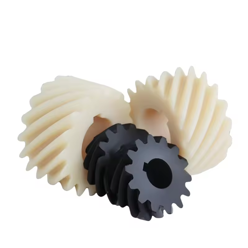
Non-parallel and Non-intersecting Gears
With these gears, the shafts are neither parallel nor intersecting.
The main types are worm gears and crossed helical gears.
They are ideal for extreme speed reduction, feature a compact design suitable for limited spaces, and are most commonly applied in elevators.
Core Gear Types and Their Mechanical Structures
Gear Types and Mechanical Principles
Spur Gear: Simple and Efficient
Shape and Structure
Straight gear teeth are parallel to the shaft.
Cylindrical structure with external or internal teeth.
Working Principle
The gear teeth engage fully and instantly, transmitting power without axial thrust.
Performance and Applications
Deliver a power transmission efficiency of 90-95%.
Typical applications include conveyors and gear pumps.
External Gears and Internal Gears
A brief difference between external gears and internal gears is given as follows:
| External Spur Gear | Internal Spur Gear |
| Teeth on the outer surface | Teeth on the inner bore surface |
| Used in standard gear trains | Used in planetary gear systems |
Helical Gear: Quiet operation and high load capacity
Shape and Structure
Features angled gear teeth with a cylindrical profile, and the teeth are longer than those of spur gears.
Working Principle
The teeth engage gradually and generate axial thrust during operation.
Performance and Applications
Capable of handling higher loads.
It operates with lower noise, making it ideal for automotive transmissions.
Single Helical vs Double Helical (Herringbone) Design
| Single-Helix | Herringbone (Double-Helix) |
| Requires thrust bearings | Two mirrored helices cancel out axial thrust loads |
| Common in pumps | Common in turbo machinery / turbines |
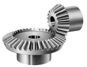
Bevel Gear: Angular Power Transmission
Shape and Structure
Bevel gears feature a conical shape with angled teeth, and their mounting shafts intersect with each other.
Working Principle
Transmits power between non-parallel intersecting shafts.
Performance and Applications
Delivers higher torque, runs smoothly with low noise.
Widely used in load-bearing equipment and aerospace applications.
Straight Bevel Gear, Spiral Bevel Gear and Hypoid Gear
| Type | Tooth Design | Advantages | Applications |
| Straight Bevel | Straight, tapered teeth | Simple, low-cost | Differential drive systems |
| Spiral Bevel | Curved, angled teeth | Quieter operation | Helicopter transmissions |
| Hypoid | Offset, spiral teeth | Compact, high torque | Automotive rear axles |
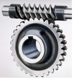
Worm Gear: Compact Gear Ratio and Self-Locking
Shape and Structure
Shafts are non-parallel.
Consists of a worm (screw) and a worm wheel (gear).
Working Principle
The worm thread slides against the teeth of the worm wheel.
Performance and Applications
Features self-locking capability.
Commonly used in conveyor brakes.
Rack and Pinion: Convert Rotary Motion to Linear Motion
Shape and Structure
Composed of a pinion (circular gear) and a rack (flat straight toothed bar).
Working Principle
The rotating pinion drives the rack to move in a straight line.
Performance and Applications
Delivers precise linear motion.
Widely applied in CNC machine tools and steering systems.
Planetary Gear: High Precision and Torque Density
Shape and Structure
Consists of sun gear (center), planet gears (orbiting) and ring gear (outer).
Working Principle
Multiple meshing contact points evenly distribute the load.
Performance and Applications
Delivers high torque within a compact space.
Used in robotics and wind turbines.
Spline Gear: Multi-Key Shaft Connection
Shape and Structure
Longitudinal teeth machined on the shaft or hub.
Working Principle
Multiple teeth distribute torque evenly.
Performance and Applications
Allows sliding shaft connection.
Applied in tractors and aircraft.
Advanced Gear Types for Specialized Applications
Specialized applications cover aerospace and robotics. These scenarios involve complex mechanical structures and adopt high-end, precision-engineered advanced gears.
Harmonic Drive Gears (Robotics & Aerospace)
Also known as strain wave gears. They operate by meshing a flexspline deformed by an elliptical wave generator with a rigid circular spline.
Key Characteristics:
- Zero backlash – critical for robotic arms
- Compact and lightweight structure
- Ultra-high precision for surgical robots
Applications
- Industrial robotic arms such as Fanuc and KUKA
- Deployment of satellite solar panel arrays
Magnetic Gears: Non-Contact Torque Transmission
Magnetic gears transmit torque by utilizing permanent magnets arranged in pole pieces without any physical contact. Multiple components are used to control magnetic flux, including the outer rotor, inner rotor, and stationary module.
Core Advantages
- Maintenance-free gear operation
- Silent performance
- Overload protection
Applications
- Wind power generators
- Electric vehicle transmission systems
Non-Circular Gears
Working Principle
Feature oval, triangular, or custom profile pitch curves instead of standard circular shapes.
Convert constant input speed into programmable output motion.
Key Properties
- Speed regulation: Output rotational speed varies with each revolution
- Mechanical programming: Replaces cam systems in packaging machinery
The table below summarizes the above content.
| Type | Torque Range | Platform Accuracy | Best Suited For | Cost Factor |
| Harmonic Drive | 1–500 Nm | ±0.1 arcmin | Robotics, Aerospace | 4× |
| Magnetic Gear | 5–200 Nm | ±0.5° | Medical Devices, Electric Vehicles | 5× |
| Non-Circular Gear | 1–200 Nm | Speed-dependent | Packaging, Printing | 3× |
Types of Gear Tooth Profile Design and Their Impacts
Gear tooth profile type affects gear performance, service life, efficiency, and other key characteristics. This section discusses different gear tooth design types and their influences on gear performance.
Tooth Profile Comparison: Straight Tooth, Helical Tooth, Curved Tooth
Spur Gear Tooth
Shape: Straight profile, parallel to the gear shaft.
Key Features:
- High efficiency (98–99%)
- Simple and cost-effective to manufacture
Best suited for low-speed, high-torque applications such as conveyors and manual transmissions.
Helical Gear Tooth
Shape: Angled and tapered tooth profile.
Features: Quieter operation and higher load capacity.
Ideal for industrial pumps and automotive transmissions.
Curved Gear Tooth
Shape: Curved profile with multiple pressure angles.
Features:
- Smoother meshing performance
- Better tolerance for misalignment
This type of gear tooth is most suitable for aerospace equipment and high-precision gearboxes.
Gear Grinding vs Hobbing: Which Is Better?
Gear hobbing delivers faster processing speed but leaves micro burrs on the surface, while gear grinding can achieve a surface finish of Ra 0.2μm.
| Machining Method | Process Application | Accuracy | Best Suited For |
| Gear Hobbing | Cutting teeth with a rotating hob | ±0.05 mm | High-volume spur / helical gear production |
| Gear Grinding | Finish-cutting pre-machined teeth with a grinding wheel | ±0.005 mm | High-precision applications (e.g., aerospace, robotics) |
Backlash Control Strategy
Backlash is a common issue between meshing gear teeth. It causes positioning errors and vibration. That is why it is critical to resolve this problem.
Strategies to solve the problem:
- Design modification
- Manufacturing correction
- Maintenance adjustment
Optimal Materials for Different Gear Types
Choosing inappropriate gear materials will compromise mechanical properties and further degrade gear performance. Let’s take a look at the most suitable materials for various gear types and the reasons behind them.
Steel Alloys: Strength and Weight
In this table, you can view different steel alloys used for gear applications. Steel offers high load capacity with a torque rating of over 500 Nm, while featuring a relatively heavy weight.
| Alloy Type | Hardness (HRC) | Tensile Strength (MPa) | Key Advantages | Common Applications |
| AISI 4340 | 28–32 | 1,000–1,200 | Toughness, fatigue resistance | Automotive transmissions |
| 8620 (Case-hardened) | 58–62 (surface) | 800–1,000 | Wear-resistant surface, ductile core | Aerospace gearboxes |
| Stainless Steel (17-4PH) | 40–45 | 1,100–1,300 | Corrosion resistance | Marine, food processing equipment |
Plastics and Composites: Quiet, Lightweight Solutions
Plastics and composite materials are lightweight and ideal for noise-sensitive applications.
| Material | Tensile Strength (MPa) | Max Temperature (°C) | Key Advantages | Common Applications |
| PA66 (Nylon 6/6) | 80–90 | 120 | Self-lubricating, noise-dampening | Conveyor systems, printers |
| Polycarbonate (PC) | 55–75 | 135 | Impact-resistant, transparent | Food-safe machinery |
Emerging Materials: Carbon Fiber and 3D-Printed Gears
Carbon fiber and 3D-printed gears are emerging materials in the gear industry. They are specialized materials applied for prototyping and extreme working conditions.
| Material | Strength-to-Weight Ratio | Unique Benefits | Current Limitations |
| Carbon Fiber Reinforced | 5× higher than steel | Near-zero thermal expansion, vibration damping | Brittle under impact loading |
| 3D-Printed Titanium Alloy | Comparable to 4340 steel | Enables complex geometries (e.g., topology-optimized gear teeth) | High cost (~$5000/kg) |
Gears in Robots: Precision Requirements and Trends
Robotics is an emerging technology for manufacturing robots. Such robots require gears with extremely high precision and reliability. This explains how gears meet the performance requirements of robots.
Collaborative Robots vs Industrial Robots: Gear Specifications
Examples of two major robot types are listed, with specified corresponding requirements for gears.
| Specification | Collaborative Robots | Industrial Robots (e.g., SCARA, 6-axis) |
| Torque | 5–50 Nm (safety-limited) | 50–500 Nm (high-power motors) |
| Backlash | <0.01 mm (human-safe precision) | <0.05 mm (speed/precision balance) |
| Size | Compact (Ø20–50 mm gears) | Larger (Ø50–200 mm gears) |
| Key Technologies Used | Harmonic drives, planetary gears | Precision helical gears, cycloidal drives |
Micro Gears for Surgical and Micro Robotics
These gears have extremely small teeth, smaller than a human hair, with a module of 0.1–0.5 mm.
To meet these requirements, the following materials may be used:
- Stainless Steel
- PEEK
- Ceramics
Backlash-Free Design for Improved Positioning Accuracy
It is essential to understand backlash. Backlash refers to the clearance between meshing gear teeth, which can cause positioning errors.
For backlash-free designs, the following design modifications are applied:
- Preloaded Dual Gears
- Flexible Splines
- Torsionally Rigid Materials
Gear Design Considerations for Engineers
To improve gear efficiency, engineers must understand the following design-related concepts:
How to Calculate Gear Load Capacity (AGMA Standard)?
Determine Basic Parameters
- Module
- Number of teeth
- Face width
- Calculate bending stress
- Calculate contact stress
- Compare with AGMA allowable stress
How to Select Lubrication for Heavy-Duty Gears?
Lubrication for heavy-load gears is selected according to the application.
Extreme pressure (EP) gear oil is suitable for high-torque industrial applications.
How to Reduce Gear Noise in Precision Systems?
Below are advanced techniques to reduce noise in precision systems:
- Tooth profile optimization
- Material damping
- Micro-geometric correction
Why Are Custom Gears So Expensive and Hard to Source?
Custom gears are costly, complex to manufacture, and difficult to find. Their design is sophisticated, requiring advanced dedicated machinery for production.
Why Do Standard Gears Fail to Meet Modern Requirements?
There are several key reasons:
- Lightweight design is a top priority in the transportation industry, while standard gears are too heavy for installation.
- Standard gears do not adopt advanced materials.
- The geometry of standard gears is incompatible with modern machinery.
Why Are Small-Batch Gears More Costly?
Small-batch gears come with higher costs due to low production volume. See the table below:
| Factor | Low Volume (50 units) | Mass Production (10,000+ units) |
| Setup Time | 8–12 hours (CNC programming, fixturing) | Amortized to minutes per unit |
| Tooling/Mold Cost | $500–$2,000 (custom hobs/grinding wheels) | $0.10 per unit |
| Material Waste | 30–50% (test runs) | <5% (optimized processes) |
| Unit Cost | $50–$500 per component | $1–$20 per component |
Alternative Solutions: Modular Kits and 3D Printing
Modular gear kits are prefabricated gear modules, costing 50% less than custom gears.
3D printing uses advanced materials such as SLS nylon to produce gears and can also fabricate complex geometric shapes. It incurs zero daily tooling costs.
Conclusion
This article covers gears, gear types, and gear tooth profile design. It can be concluded that gears are an essential component of all machinery, ranging from bicycles to aircraft.
Gears are specialized components for power transmission and play a vital role in the design of robotics. A wide range of advanced materials, composite materials, and cutting-edge technologies such as 3D printing are widely adopted to manufacture specialized gears for robotic applications.
FAQ
What are the three functions of gears?
- Speed adjustment
- Torque multiplication
- Changing the direction of motion
What is the most common type of gear?
Spur gears feature a simple structure and high working efficiency, which makes them the most common type of gear.