Published by Zorapid
If you run a CNC shop building aerospace brackets, EV housings, medical fixtures or automation frames, aluminum 6061-T6 and 7075-T6 are your daily workhorses.
But here’s the costly mistake 70% of machinists make: running identical high-speed milling settings for both alloys.
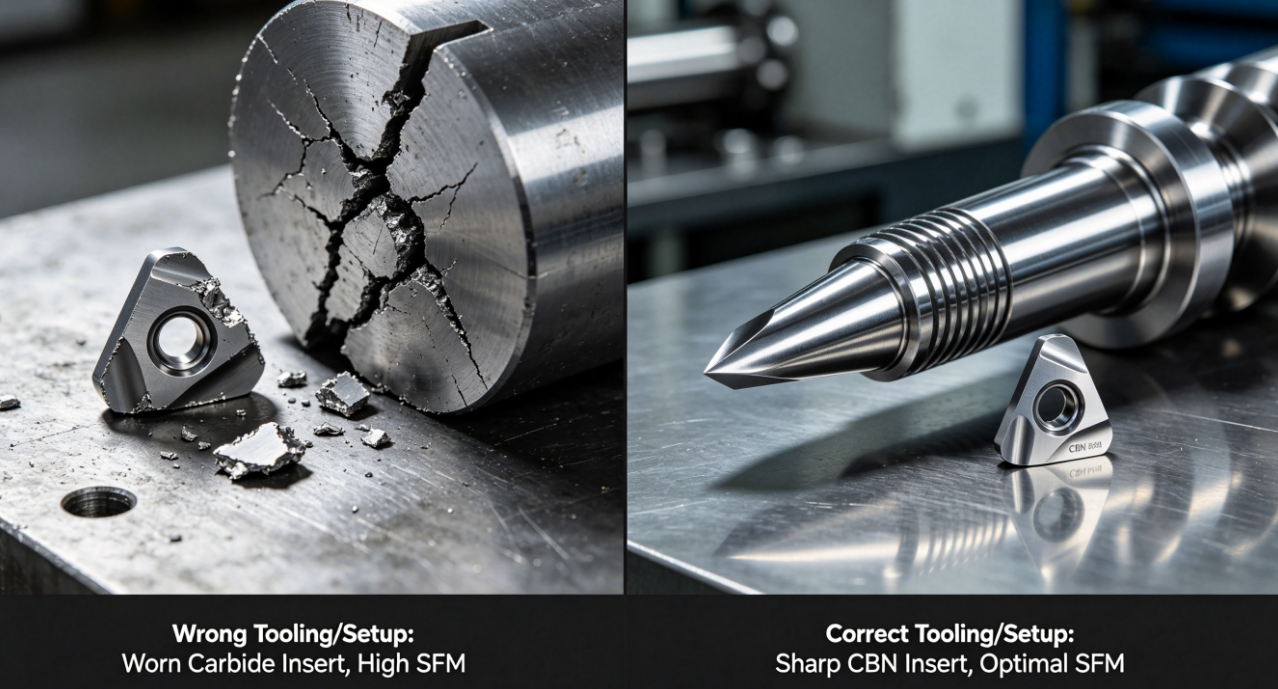
6061-T6 is soft, gummy, and prone to built-up edge (BUE). 7075-T6 packs copper and zinc, making it stronger, more abrasive, and far less forgiving of lazy feeds/speeds. At Zorapid, we process thousands of aluminum precision parts monthly with 5-axis high-speed mills. We’ve scrapped blanks, snapped end mills, and fixed terrible surface finishes from misaligned HSM workflows.
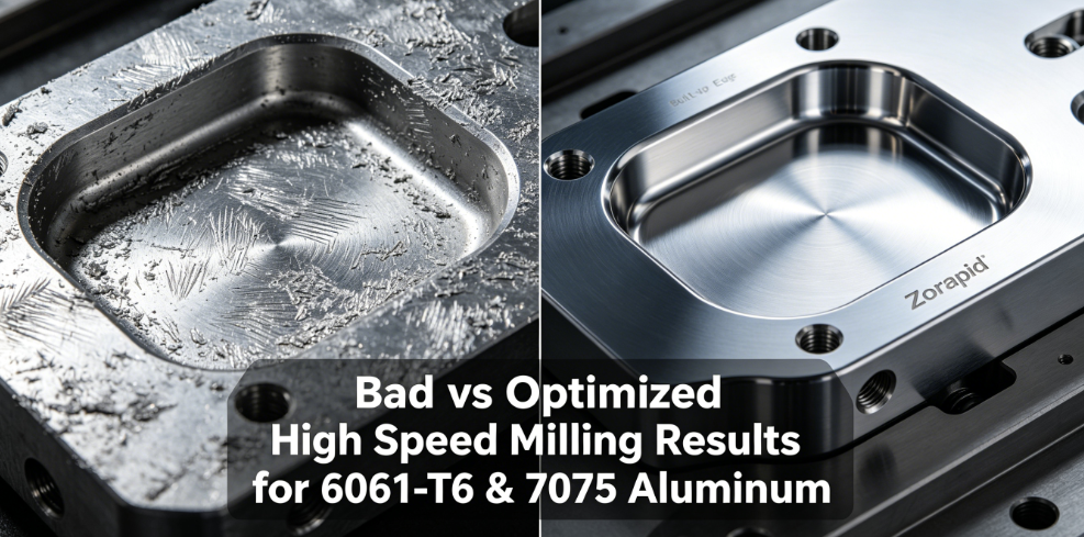
This guide breaks down actionable, shop-ready high-speed milling tips split for 6061 and 7075. No textbook fluff—just real-world tweaks to cut cycle time, slash scrap, boost surface finish Ra <0.8μm, and extend carbide tool life.
Understand The Core Difference Between 6061-T6 & 7075-T6 For HSM
Before touching spindle RPM, grasp how each alloy reacts under high-speed cutting:
- 6061-T6 (General Purpose Aluminum) Low copper content, soft ductile matrix. Machines fast but aluminum chips weld instantly to cutter flutes if chip load is too light. Low tool abrasion, forgiving of minor setup flaws. Perfect for prototypes, chassis, non-structural parts.
- 7075-T6 (High-Strength Aerospace Grade) High Cu/Zn alloyed, tensile strength nearly double 6061. Chips break cleanly (less gummy) but grind carbide edges fast. Demands rigid fixturing, reduced cutting depths, and lower SFM than 6061. Used for load-bearing aircraft, drone frames, racing components.
Quick Comparison Table
| Feature | 6061-T6 High Speed Milling Rule | 7075-T6 High Speed Milling Rule |
|---|---|---|
| Core flaw risk | Built-up edge, smearing surface finish | Rapid flank tool wear, chatter, dimensional shift |
| Base cutting speed | 1200–3000 SFM | 900–1800 SFM (20–30% slower vs 6061) |
| Ideal chip load per tooth | 0.004–0.008” rough; 0.001–0.003” finish | 0.003–0.006” rough; 0.001–0.002” finish |
| Max axial rough depth | Up to 2× tool diameter | Max 1× tool diameter (shallow cuts reduce wear) |
| Coolant priority | Chip evacuation > cooling | Heavy flood cooling to control heat buildup |
Pick The Exact End Mill Geometry For Each Aluminum Alloy
Tool choice makes or breaks high-speed aluminum milling. Skip generic steel cutters—they guarantee BUE and chatter.
For 6061-T6 HSM
- Flute count: 2 or 3-flute solid carbide. Extra open flutes clear gummy chips fast. Avoid 4+ flutes—swarf packs instantly at high RPM.
- Helix angle: 38°–45° high helix. Pulls chips away from cut zone before welding to edges.
- Coating: Uncoated polished carbide or ZrN. Never TiAlN/TiCN coatings—they create friction that sticks aluminum chips to flutes.
- Edge prep: Sharp, honed micro edges. Rounded edges rub material and spark BUE.
For 7075-T6 HSM
- Flute count: 3-flute balanced carbide. Balances chip room and structural rigidity for harder alloy cuts.
- Helix angle: 35° moderate helix. Less aggressive than 6061 tools to resist edge chipping under heavy cutting force.
- Coating: ZrN or DLC diamond coating for high-volume runs. DLC extends tool life 3–5x on batch 7075 jobs.
- Edge prep: Light T-land hone to stop rapid abrasive flank wear.
Optimize SFM, RPM & Chip Load
The error we see at Zorapid clients: copying 6061 feeds directly onto 7075 stock. Let’s break usable starting points you can dial up/down 10% based on machine rigidity.
6061-T6 High Speed Milling Starting Settings (Carbide Tools)
- Roughing Adaptive Clearing SFM: 1800–2400 | Chip load 0.005–0.007 IPT | Axial depth 1.5× tool diameter
- Finishing Profile/Pockets SFM: 2200–3000 | Chip load 0.0015–0.0025 IPT | Light 0.01–0.02” finishing pass
- Slotting (100% width of cut) Drop SFM to 1200–1600, cut chip load 20% lower to avoid flute packing
7075-T6 High Speed Milling Starting Settings (Carbide Tools)
- Roughing Adaptive Clearing SFM: 1300–1700 | Chip load 0.004–0.006 IPT | Axial depth max 1× tool diameter
- Finishing Profile/Pockets SFM: 1600–2000 | Chip load 0.001–0.002 IPT | Two light finishing passes for tight ±0.005mm tolerance
- Slotting (100% WOC) SFM cut by 35% vs side milling, reduce feed drastically to stop tool breakage
Quick shop hack: If you see aluminum smearing on 6061 edges, raise chip load 10%. Light chip loads rub material instead of shearing cleanly, creating instant BUE. For 7075, if edges wear after 20 parts, drop SFM 15% or switch to DLC coated cutters.
Master Coolant & Chip Evacuation To Kill BUE & Heat Distortion
Aluminum melts at low temperatures. High spindle RPM cranks friction heat—poor cooling warps thin walls and ruins surface finish. Split rules per alloy:
6061-T6 Cooling Strategy
Top priority: Blast chips away fast, not just flood coolant.
- Small prototype runs: Air blast + MQL mist oil. Minimal liquid prevents messy gummy chip buildup.
- Large roughing runs: Flood coolant aimed directly into flute cut path. Clear chips before they recut and weld onto edges.
- Avoid standing coolant pools inside deep pockets—trapped hot chips create smearing marks.
7075-T6 Cooling Strategy
Top priority: Full heat suppression to stop thermal distortion and abrasive wear.
- Mandatory high-pressure flood coolant for all high-speed cuts. Copper alloy additives generate more heat than 6061.
- Direct coolant jet to both flank and rake face of the cutter. Dual streams cut tool wear in half during batch production.
- Deep pocket milling: Add air blast alongside flood to lift broken hard 7075 chips out of tight cavities.
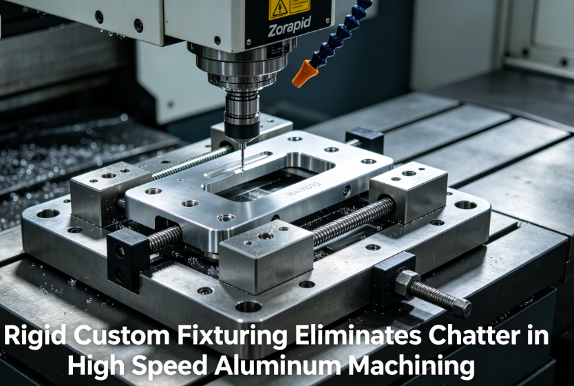
Rigid Fixturing & Anti-Chatter Setup
High-speed milling amplifies vibration. Even tiny flex creates rippled chatter marks on finished aluminum surfaces.
Universal Rules For Both Alloys
- Clamp stock as close to the cut zone as possible. Overhang longer than 1.5” guarantees vibration.
- Minimize tool stickout. Shorter cutters = far less chatter at 12,000+ RPM.
- Use solid steel vises, vacuum tables, or custom fixture jigs for thin-wall aluminum parts. Plastic soft jaws flex too easily.
Alloy-Specific Tweaks
- 6061 thin walls (0.8–1.2mm): Use support ribs in your CAM program. Soft aluminum deflects under high feed pressure, causing inconsistent wall thickness.
- 7075 structural thin walls: Reduce finishing feed rate 20% and add support fixtures. High tensile strength creates sharp vibration resonance at high spindle speeds.
CAM Toolpath Hacks To Cut Cycle Time & Improve Finish
Generic standard toolpaths waste time and damage aluminum surfaces. Use these Zorapid-proven HSM CAM strategies:
- Adaptive Trochoidal Clearing (for both alloys) Replace straight slotting with trochoidal roughing. Lighter radial engagement slashes cutting force, reduces heat, and lets you run higher spindle speeds safely. Cycle time drops 20–30% on deep pockets.
- Avoid sharp 90° direction changes Add small radius blending to all toolpath corners. Hard direction shifts spike spindle load and create visible witness lines on aluminum finishes.
- Climb Milling Only For Finishing Conventional milling pulls material into the cutter, triggering BUE on 6061 and heavy edge wear on 7075. Lock climb milling for all high-speed finishing passes.
- Separate roughing and finishing operations fully Never finish immediately after roughing without clearing chips and letting stock cool. Residual heat from roughing warps 7075 blanks enough to miss tight tolerance specs.
DFM Design Adjustments For Faster, Flawless High Speed Milling
Many machining headaches start at the design stage. Our engineering team applies these DFM rules before loading any aluminum blank onto HSM machines:
- Internal pocket radii Minimum R3mm internal radii for both alloys. Tiny R0.5/R1 radii force tiny fragile end mills that break at high RPM and slow production 2–4x.
- Wall thickness limits 6061 minimum wall: 1.0mm minimum (1.5mm preferred for HSM thin-wall jobs). 7075 minimum wall: 1.2mm minimum (higher strength alloy vibrates more easily at thin gauges).
- Avoid deep narrow slots Slots deeper than 3× width require extended tool stickout—major chatter risk in high-speed milling. Split deep features into two machining setups.
- Tolerance practicality Reserve ±0.003–0.005mm tight tolerances only for mating surfaces. Loosen non-critical features to ±0.02mm to skip extra slow finishing passes and lower production cost.
Real Zorapid Case Study – 7075 Aerospace Bracket High Speed Milling Overhaul
A US aerospace client sent us a failing production run of 7075-T6 mounting brackets. Their original process reused 6061 high-speed parameters, creating three critical failures:
- 40% scrap rate from snapped carbide cutters
- Severe flank wear requiring tool changes every 12 parts
- Visible chatter ripples failing surface inspection Our Zorapid engineering team’s HSM fixes:
- Swapped generic 4-flute cutter for 3-flute DLC coated medium-helix carbide
- Dropped spindle SFM by 28%, reduced axial rough depth from 2D to 1D
- Added dual high-pressure flood coolant jets + custom zero-flex fixture ribs
- Rewrote CAM toolpaths with full trochoidal adaptive clearing
Final results: Scrap rate fell to under 2%, tool life extended 4.2x, cycle time per bracket cut 24%, surface finish hit consistent Ra 0.4μm for aerospace inspection pass.
Quick Troubleshooting Cheat Sheet For Common HSM Aluminum Issues
Scan this section when you hit problems mid-run—no need to dig through long manuals.
- 6061-T6 Surface smearing / BUE buildup Fix: Raise chip load per tooth, switch to polished high-helix ZrN end mill, boost coolant chip blast flow.
- 7075-T6 Fast tool flank wear Fix: Drop SFM 15–20%, upgrade to DLC coating, add dual flood coolant streams to cutter edges.
- Chatter ripples on finished walls (both alloys) Fix: Shorten tool stickout, add support fixturing, lower finishing spindle speed slightly, switch to trochoidal toolpaths.
- Thin aluminum walls deflecting, inconsistent dimensions Fix: Follow DFM minimum wall thickness, add temporary support ribs in CAM, reduce feed rate on light finishing passes.
- Tool snapping during slotting cuts Fix: Reduce radial width of cut, cut spindle speed, clear chips continuously with air blast + flood coolant.
Why Choose Zorapid For High Speed Milling 6061 & 7075 Aluminum
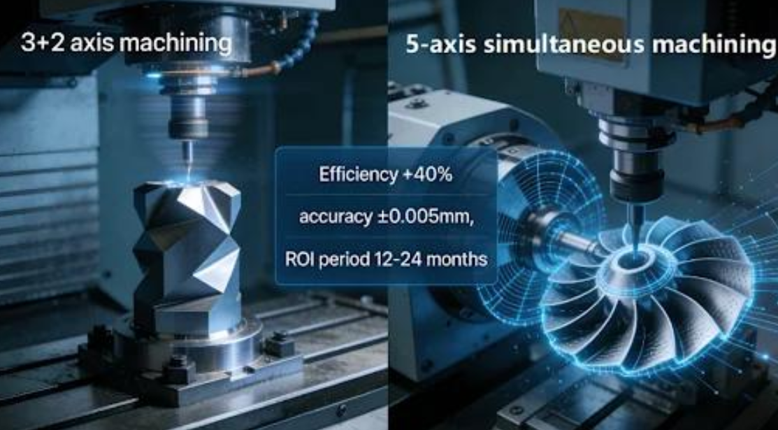
We specialize in hybrid high-speed 5-axis milling for precision aluminum parts across aerospace, medical, EV, automation and drone industries. Our core advantages for aluminum HSM jobs:
- 3,000㎡ dedicated precision manufacturing center with 12 high-speed 5-axis CNC mills calibrated daily for aluminum alloy cutting
- In-house material & process engineers to run DFM reviews and custom HSM parameter sets before production
- Exclusive DLC/ZrN carbide tool inventory optimized separately for 6061-T6 and 7075-T6 batches
- High-pressure coolant systems + custom modular fixturing to eliminate chatter and thermal distortion
- Full batch inspection with AI vision metrology to hold consistent tight tolerances on high-speed milled aluminum components
- Fast lead times: Prototypes in 3–5 days, medium/large aluminum production runs delivered in 7–12 business days
Final Key Takeaways
- Never mirror 6061-T6 high-speed milling settings onto 7075-T6—7075 needs slower SFM, shallower cuts, and heavy flood cooling.
- Tool geometry is non-negotiable: High-helix open flutes for gummy 6061, rigid balanced 3-flute DLC cutters for abrasive high-strength 7075.
- Chip evacuation beats raw cooling power for stopping built-up edge on 6061 aluminum.
- Rigid fixturing and trochoidal CAM toolpaths eliminate chatter, the biggest enemy of clean HSM aluminum surface finishes.
- Early DFM design tweaks cut cycle time, scrap, and tool replacement costs by 20–40% on every aluminum project.
FAQ
Can I run the same end mill for both 6061-T6 and 7075-T6 high speed milling?
You can for small prototype runs, but it sacrifices efficiency and tool life long-term. For batch production, keep dedicated high-helix tools for 6061 and rigid DLC coated cutters for 7075.
What’s the ideal surface finish Ra I can hit with high speed aluminum milling?
Optimized HSM workflows deliver Ra 0.2–0.8μm for both alloys with proper finishing passes and anti-chatter setup. As-machined standard roughing sits at Ra 1.6–3.2μm without fine finishing steps.
Is high speed milling worth it for low-volume aluminum prototypes?
Absolutely. HSM adaptive clearing slashes roughing cycle time, creates cleaner chips with less manual deburring, and avoids thermal warping common with slow conventional milling.
How much slower should I run 7075 vs 6061 in high speed milling?
Drop SFM by 20–30% for all roughing and finishing operations on 7075-T6 to control abrasive tool wear and heat buildup.
Does air blast work for high speed milling 7075-T6?
Only for tiny light finishing touches. High-strength 7075 generates far more cutting heat—full flood coolant is mandatory for all roughing HSM passes to prevent thermal distortion.