Published:Zorapid.Ltd
If you’ve worked with 5-axis CNC suppliers long enough, you’ve likely lived this frustration:
You send out a CAD file and drawing, the shop quotes the job, parts arrive… and they don’t fit.
The root cause is rarely poor machining. More often than not, it’s unclear, inconsistent, or overly aggressive tolerance specifications.
5-axis parts carry complex angled surfaces, compound radii, deep undercuts, and multi-orientation features. Ambiguous tolerances create misalignment between your expectations and how your supplier interprets the print. Vague specs lead to inflated costs, longer lead times, unnecessary scrap, and failed assembly testing.
In this guide, we break down exactly how to structure tolerance callouts for 5-axis projects. We cover common mistakes, practical drafting rules, GD&T best practices, and how to align expectations so your supplier delivers parts that work the first time. We’ll also explain how Zorapid eliminates miscommunication through standardized drawing review for all 5-axis precision orders.
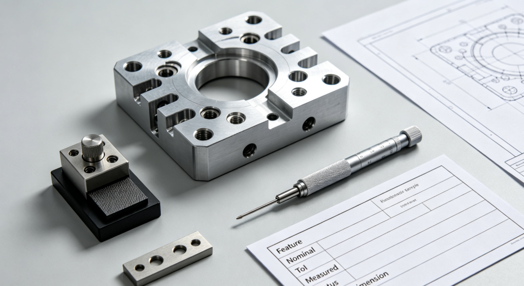
Why Tolerance Rules for 5-Axis Are Different From 3-Axis Machining
Standard 3-axis drawings focus mostly on orthogonal X/Y/Z dimensions. Most features sit parallel or perpendicular to primary datums.
5-axis changes everything:
- Features sit at compound angles to the main part plane
- Many surfaces are only accessible with simultaneous multi-axis movement
- Rotary axes introduce additional stack-up error
- Datum alignment becomes critical for angled holes, contoured surfaces and curved profiles
- Measuring complex geometry requires CMM probing at multiple orientations
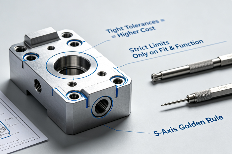
A generic “±0.05 mm everywhere” blanket tolerance doesn’t translate well. Suppliers cannot apply uniform precision to all angled features without knowing which surfaces are functionally critical.
Over-tolerancing every feature forces the machine to run slower, use special tooling and add extra inspection steps. That directly pushes your price up.
Under-tolerancing critical features leads to non-conforming parts that cannot be reworked.
Separate Features Into Three Tolerance Classes
Before you touch your drawing, sort every feature by function. This simple framework prevents blanket tolerance abuse.
- Critical Functional Features Mating surfaces, locating holes, vacuum sealing faces, alignment datums, wafer contact areas. Tight GD&T required. These drive assembly performance.
- General Non-Mating Features Outer contours, non-contact curved surfaces, internal weight reduction pockets. Wider tolerances are acceptable here.
- Cosmetic / Non-Critical Geometry External radii, non-matching edge profiles. Use default drawing tolerances wherever possible.
Stop Relying Only on Linear Dimension Tolerances – Use GD&T
Linear plus/minus tolerances struggle to describe angled, contoured 5-axis geometry.
GD&T (ASME Y14.5 or ISO GPS standards) removes ambiguity by defining:
- Clear datum reference frames
- Form, orientation and position tolerances for angled holes and compound surfaces
- Profile tolerances for freeform curved surfaces
Common GD&T callouts you will use repeatedly on 5-axis parts:
- Position: For angled hole patterns, offset threaded holes on inclined planes
- Profile of a surface: For contoured, curved 5-axis machined surfaces (most important for aerospace, semiconductor fixtures)
- Parallelism / Perpendicularity / Angularity: For tilted mating faces
- Flatness: For sealing and contact surfaces
A frequent mistake we see: Engineers dimension angled features using projected linear measurements without angularity controls. The result: different inspectors and suppliers interpret measurements differently.
Write Explicit Blanket Tolerance Notes (Avoid Hidden Assumptions)
Every drawing should include a clear general tolerance block. Do not leave your supplier guessing.
Example template you can copy directly onto prints (metric):
GENERAL TOLERANCES UNLESS OTHERWISE SPECIFIED:
Linear dimensions: ±0.10 mm
Angular dimensions: ±0.5°
Radii: ±0.15 mm
Threads: Standard 6H / 6g fit
Surface finish: Ra ≤ 3.2 μm unless noted
If you use imperial units, adjust values accordingly.
Important 5-axis addition to your drawing notes:
All profile tolerances apply normal to the contoured surface.
All angled feature measurements referenced to stated datum frame.
This eliminates arguments over whether tolerances apply along axes or perpendicular to curved geometry.
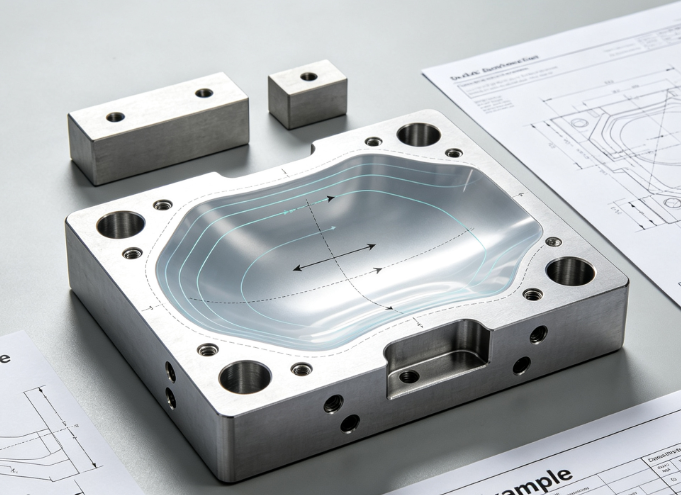
Handle Freeform Contours & Complex Profiles Correctly
5-axis simultaneous machining often produces swept surfaces and organic contours.
Bad practice: Dimensioning dozens of points along a curve with linear tolerances. This creates measurement chaos.
Good practice: Apply a Profile of a Surface tolerance relative to your datum set.
Include this note if relevant:
Profile tolerance includes size, form, orientation and location variation.
Also specify:
- Whether the profile tolerance is unilateral or bilateral
- Allowance for material boundary (outer stock vs machined net shape)
Clearly State Datum Strategy for Multi-Axis Workpieces
Many 5-axis parts can be fixtured in multiple orientations. If your datums are ambiguous, alignment shifts during machining and inspection.
Best practices:
- Establish 3 primary datums (A, B, C) forming a stable reference frame
- Select datums that are accessible for both machining and CMM inspection
- Avoid using small, fragile thin-walled features as primary datums
- If secondary rotary datums exist, document them explicitly
When angled holes are present, reference them back to the main datum frame, not local sketch planes inside your CAD model. CAD internal planes are invisible to your supplier’s inspection team.
Document Surface Roughness & Edge Requirements
Tolerances are not only dimensional. For semiconductor, vacuum and cleanroom components, surface finish and burr specifications are just as critical.
Write clear notes such as:
- Ra ≤ 0.4 μm on all contact surfaces
- All edges deburred, radius 0.1–0.3 mm, no micro-burrs
- No manual abrasive polishing permitted on precision datum faces
If you omit these, suppliers may use cost-saving deburring methods that leave residual particles.
Add Inspection Expectations in Drawing Notes
Remove guesswork by defining how features should be verified:
- CMM inspection required for all position and profile GD&T callouts
- Report critical dimensions upon request
- Indicate if 3D scanning is acceptable for contour validation
Most Common Costly Tolerance Mistakes on 5-Axis Drawings
- Over-specifying tolerances everywhere Every extra tight tolerance increases cycle time, requires slower feedrates and more setups. Your quote will jump significantly.
- Mixing ISO and ASME GD&T standards without clarification EU shops often follow ISO GPS; US fabricators default to ASME Y14.5. State your standard on the title block.
- No distinction between as-machined and post-treatment dimensions If parts go through anodizing, coating or heat treatment, specify whether tolerances apply before or after surface treatment.
- Dimensioning to theoretical sharp corners 5-axis tools leave radii. Add a note defining allowed edge break or minimum radius.
- CAD model and 2D drawing mismatch Always confirm the 2D drawing takes priority, or specify “CAD model governs”. This avoids endless disputes.
Why Zorapid Helps You Avoid Tolerance Miscommunication on 5-Axis Orders
Lots of workshops can run 5-axis machines. Few perform a formal drawing and tolerance review before quoting. Here is how Zorapid reduces risk for your multi-axis projects:
Pre-quote engineering drawing review
Our team scans every drawing for ambiguous tolerances, conflicting GD&T, unrealistic profile specs and missing datum definitions. We flag issues before machining starts, not after parts are finished.
Deep experience with 5-axis complex geometry
We regularly machine contoured fixtures, semiconductor tooling, aerospace components and vacuum parts. Our engineers understand how rotary axis movement impacts achievable tolerances on angled and curved surfaces.
Transparent feedback on unmanufacturable specs
If your tolerance stack-up or profile callout is not practically achievable with standard 5-axis processes, we propose balanced alternatives to maintain function while controlling cost.
Consistent inspection aligned with your drawing standards
We follow either ASME Y14.5 or ISO GPS as specified. Critical GD&T features are verified via CMM, and full inspection reports can be provided on demand.
DFMA input for 5-axis manufacturability
We can adjust suggested tolerances during design review. We highlight opportunities to relax non-critical specs to lower cost and shorten lead time without hurting part performance.
Standardized communication workflow
We confirm all tolerance interpretations in writing at project kickoff. No assumptions, no verbal agreements that get lost between sales, programming and quality teams.
FAQ
Should I send suppliers 2D drawings or just the 3D CAD model for 5-axis parts?
Always supply both. The 3D model is used for toolpath programming. The annotated 2D drawing defines tolerances, GD&T, datums, surface finish and acceptance rules. Relying solely on STEP/IGES files leaves zero formal tolerance reference and creates huge risk.
What profile tolerance is realistic for standard simultaneous 5-axis machining?
For typical aluminum components, ±0.03 ~ ±0.08 mm profile is achievable under stable conditions. Tighter profile below ±0.02 mm requires slower finishing passes, rigid fixturing and specialized tooling, which raises pricing. We can confirm realistic limits during drawing review.
Can I use different tolerance values for rough stock vs finished features?
Absolutely. Clearly separate semi-finish allowance tolerances and final net-shape tolerances on your print. If you outsource post-processing (anodizing, coating), explicitly state whether tolerances apply pre or post coating.
How do I write tolerances for angled drilled holes on 5-axis components?
Avoid simple linear dimension chains. Use a Position tolerance referenced to your primary datum frame, with angularity control if needed. This correctly captures orientation error, which is the biggest risk for tilted hole patterns.
What happens if my drawing has conflicting tolerance requirements?
At many suppliers, the first batch becomes a test. At Zorapid, our engineering review catches conflicts at quoting stage. We send a formal clarification list before we lock the order, preventing scrap and delays.
Is a blanket profile tolerance acceptable for all curved surfaces?
Generally not. Differentiate functional sealing/mating contours from non-critical aesthetic curves. Applying tight profile tolerances across every curved surface will unnecessarily increase your manufacturing cost.
Should I specify tolerance differences between prototype and production batches?
Yes. If you accept wider variation for initial R&D prototypes, state this clearly on the drawing or purchase order. For serial production, we lock validated 5-axis setups to maintain consistent tolerance repeatability.
Closing Thoughts
Clear tolerance specifications act as a binding agreement between you and your 5-axis machining supplier. Poorly written callouts create costly surprises, delays and endless back-and-forth during quality checks.
Start by separating critical and non-critical features, use proper GD&T for angled and contoured geometry, lock down your datum strategy, and eliminate ambiguous blanket rules.
If you want a second set of eyes to review your 5-axis part drawings before sending out RFQs, the engineering team at Zorapid can help. We evaluate your tolerance scheme for manufacturability, flag risky specifications, and deliver precision multi-axis machined parts aligned exactly to your drawing requirements.
Share your CAD and drawing files today for a quote and complimentary tolerance review.