
Published:Zorapid.Ltd
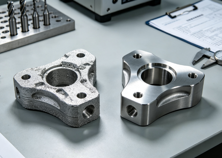
SLM (Selective Laser Melting, PBF-LB/M) 3D printing creates complex biomimetic lattices, conformal cooling channels, internal fluid passages, and gradient geometry impossible to produce via conventional machining—but suffers from poor as-built precision (±0.1mm typical), rough surface finish (Ra 10–25μm), micro-porosity, anisotropic material properties, and residual stress distortion.
5-axis CNC finishing solves precision functional requirements: critical mating flanges, threaded interfaces, bearing seats, sealing surfaces, and instrument datums that demand tight GD&T tolerances, low runout, and validated surface integrity.
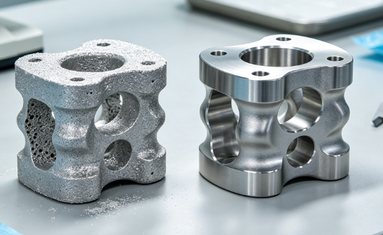
Hybrid manufacturing = SLM builds near-net-shape complex core geometry (lattices, conformal channels) + validated post-processing + 5-axis selective finishing only on critical functional zones (not full-part machining). This balances geometric freedom and precision performance for orthopedic implants, aerospace turbine components, conformal cooling mold inserts, and motorsport parts.
SLM Hybrid Material Basics & Powder Validation
Common SLM Alloys
- Ti6Al4V / Ti6Al4V ELI (Grade 5/23): medical orthopedic implants, aerospace structural components
- Inconel 718 / Hastelloy X: gas turbine hot-end parts, energy components
- AlSi10Mg / Scalmalloy: aerospace brackets, conformal cooling mold inserts, UAV frames
- 316L / 17-4PH: fluid manifolds, valve bodies, semiconductor hardware
Powder & Material Compliance Rules
- Validate powder chemistry, particle size distribution, oxygen content, recycling protocols (regulatory critical: ISO 13485, AS9100)
- Limit powder reuse cycles to avoid contamination, micro-inclusions, and inconsistent microstructure
- Record batch/powder heat-lot traceability for regulated industries
- XRF alloy verification on finished hybrid parts
- Key Material Property Note: SLM parts have anisotropic (direction-dependent) mechanical properties (different strength/stiffness parallel vs perpendicular to build layers)
- Build orientation defined upfront per DFM rules, validated via tensile/fatigue coupon testing
- As-built micro-porosity requires HIP (Hot Isostatic Pressing) for fatigue-critical load-bearing components
- Baseline As-Built Specs
- Dimensional tolerance: ±0.1mm
- Surface roughness: Ra ~10–25μm
- Required 5-axis machining stock: 0.1–0.3mm on functional finish zones (compensate for HIP shrinkage/distortion)
Core Challenges of SLM + 5-Axis Hybrid Manufacturing
- Anisotropic Material Machining: Layered microstructure causes variable cutting forces, chatter, BUE (built-up edge), inconsistent surface finish
- Residual Stress & Dimensional Drift: SLM thermal cycling creates locked-in residual stress; HIP/heat treatment causes volumetric shrinkage and distortion
- If 5-axis finishing is done before thermal processing, critical GD&T features will drift out of spec
- Lattice / Porous Geometry Risk: Directly machining porous lattices causes strut breakage, micro-debris contamination, biocompatibility risk
- Lattice zones must be masked and excluded from 5-axis cutting cycles
- Datum Alignment Variability: Asymmetric near-net-shape geometry lacks standard reference datums → 5-axis fixturing error and tolerance stack-up
- Regulatory Validation Burden: Full process validation, traceability, NDT, biocompatibility / fatigue testing for medical/aerospace end-use
- Hidden Residual Powder / Support Residues: Unremoved trapped powder/support material in lattices causes contamination, sterilization failure, fatigue crack initiation
Regulated End-to-End Workflow
1: DFM CAD Split Design
- Define 2 core zones + transition buffer zone:
- Lattice / conformal channel zones (SLM only, no 5-axis machining)
- Solid functional zones (SLM near-net + 5-axis finish machining, 0.1–0.3mm stock)
- 1.5mm+ solid transition buffer band to separate lattice and solid zones, reduce stress concentration and prevent 5-axis tool damage to lattice struts
- Add dedicated solid fixture/datum lugs (non-flight/non-end-use geometry) for repeatable 5-axis fixturing
- Create validated build orientation + support structure layout (minimize internal trapped support/powder)
- Run full 5-axis CAM collision simulation (Vericut/NX) pre-production
2: SLM Powder Bed Printing
- Inert argon atmosphere, validated laser parameters, controlled build plate temperature
- Build sacrificial datum fixture lugs as part of the SLM geometry
- Full process log: laser parameters, layer height, scan strategy, build time, powder batch ID
3: Post-Build Initial Processing
- Depowdering: automated powder removal, ultrasonic cleaning, compressed air lattice channel purging
- Support removal: wire EDM / controlled milling to remove external supports; validate no residual support in lattices
- Initial stress relief annealing (per alloy spec) to reduce raw SLM residual stress
- Pre-HIP NDT screening (CT/X-Ray): reject parts with large interconnected voids (HIP cannot fix large voids)
4: HIP + Formal Heat Treatment (Fatigue-Critical Parts Only)
- HIP cycle (Ti6Al4V: 920°C, 100MPa argon, 2hr hold): eliminate micro-porosity, improve fatigue performance
- Follow-up beta/temper annealing to refine microstructure, reduce residual stress, stabilize dimensions
- Critical Rule: All HIP/heat treatment must be completed BEFORE 5-axis precision finishing
- Record full NADCAP/AMS furnace logs for regulated aerospace/medical batches
- 24–48hr ambient soak validation post thermal cycles to identify delayed dimensional drift
5: 5-Axis Precision Finishing
- Single-setup 5-axis machining, referenced to validated primary solid datum (not lattice geometry)
- Mask all lattice zones with silicone/protective fixturing; only machine pre-defined solid functional zones
- Light finish passes to minimize new residual stress and surface damage
- In-process probing cycles for datum validation, SPC monitoring of critical GD&T features
6: Final Surface Treatments & Validation
- Controlled deburring, medical electropolish / passivation, targeted coating (mask datums)
- Full CMM GD&T inspection, NDT (DPI/CT), surface roughness validation, biocompatibility/leak testing as required
- UDI/laser traceability marking (non-lattice, non-fatigue zones)
- Batch documentation, FAI/AS9102, DHF/DFMEA records for regulated devices
7: Cleanroom Packaging & Sterilization Validation (Medical/High-Purity Applications)
- Deep ultrasonic / DI water cleaning, vacuum bake-out (semiconductor/implant parts)
- ETO/gamma sterilization validation per medical standards
DFM Design Rules: Lattice Zones vs 5-Axis Machined Zones
Lattice DFM Rules (SLM Only Zones)
- TPMS Gyroid lattice preferred for biomimetic bone ingrowth / conformal cooling
- Pore size: 500–800μm (ortho implants), strut thickness ≥0.3mm (avoid ultra-fine fragile struts)
- Self-supporting overhang angles ≥45°, minimize hidden internal support geometry
- No direct extension of lattice struts into 5-axis machined solid mating zones
- Gradual modulus transition across the 1.5mm solid buffer band to reduce stress concentration
- FEA modal validation to avoid vibration resonance
5-Axis Machined Solid Zone DFM Rules
- Unified primary GD&T datum defined on thick solid base geometry (spindle-aligned for 5-axis repeatability)
- Tight GD&T tolerances only on validated mating/thread/sealing surfaces; relax non-critical solid geometry
- Add consistent radii (R≥0.5mm), avoid sharp internal corners to reduce residual stress and chatter
- Specify uniform 0.1–0.3mm finish stock; validate HIP shrinkage offset via first article trials
- Avoid deep blind pockets and extreme thin walls in 5-axis finish zones; add DFM sacrificial supports if required
Transition Zone Rule
- 1.5mm minimum solid transition buffer between lattice and machined solid zones to prevent 5-axis tool impact damage and reduce stress risers
- Validate via FEA fatigue simulation for cyclic load applications
5-Axis Fixturing, Datum Setup & Tooling Best Practices
Fixturing & Datum Alignment
- Dedicated SLM-printed solid datum lugs / fixture pads (not direct clamping of lattice or thin walls)
- 3-point repeatable locating fixture plates, custom vacuum/soft-jig fixturing
- Full 5-axis probing cycle to reference primary datum, validate alignment offset, eliminate re-fixture stack-up
- Avoid multiple repeated re-fixturing where possible (single-setup 5-axis preferred)
- Add sacrificial support geometry for thin solid finish zones, remove in final light passes
- Machine Requirements
- Rigid trunnion/gantry 5-axis CNC with thermal compensation, glass linear scales, full collision simulation software
- Temperature-controlled enclosures (±1°C) for micron tolerance medical/aero components
- High-speed balanced spindles, HSK tooling, spindle load monitoring
5-Axis Tooling Selection
- Tool Types: Fine-grain coated carbide (TiAlN/DLC), variable pitch flutes (chatter suppression), short rigid tool holders / shrink-fit tooling to minimize overhang
- Avoid long reach tools for anisotropic SLM material finishing
- Thread whirling / form taps for medical/aero precision threads
- Damped boring bars for deep bore finishing
- Coolant: High-pressure synthetic coolant, through-spindle delivery for Ti/Inconel alloys
- Mask lattice zones to prevent coolant/swarf contamination of porous structure
- Filter coolant to eliminate fine metal swarf
- Mirror finish passes: controlled mist lubrication, avoid full flood where surface integrity is critical
- Tool Monitoring: Scheduled tool change cycles + spindle load monitoring to prevent surface damage, residual stress, and strut contamination risk
5-Axis Machining Parameters & Anisotropic Material Considerations
Core Principles
- Light depth of cut, constant chip load, trochoidal adaptive milling cycles to reduce residual stress and chatter
- Adjust parameters for anisotropic layered microstructure: reduce radial engagement vs solid billet material
- Validate finish passes with surface roughness measurement (profilometer) and micro-inspection for subsurface damage
Baseline Ti6Al4V Hybrid 5-Axis Parameters (Finish Pass)
- Spindle speed: moderate RPM, avoid excessive heat input (prevents alpha-case formation and tensile residual stress)
- Feed per tooth: low, consistent feed (0.03–0.08mm/rev)
- Axial depth of cut: 0.05–0.15mm (light skim finish only)
- Spindle speed variation (SSV) where chatter is detected
- Simultaneous 5-axis finish passes only for validated freeform solid zones, grouped similar angles to reduce B/C-axis jerk
- Final mirror skim pass: new sharp finish insert, minimal heat input, validated surface integrity
Surface Roughness Targets
- Machined critical zones: Ra ≤0.2μm (medical/aero sealing/mating zones)
- Lattice zones: controlled as-built + bead blast finish (Ra 3–6μm for bone ingrowth)
- General solid non-critical zones: Ra 1.6μm to reduce cycle time
HIP, Heat Treatment & Residual Stress Control
Residual Stress Risks
- Raw SLM residual stress + aggressive 5-axis finishing = delayed dimensional drift, fatigue microcracks, implant loosening / aero component failure
Mitigation Process
- Initial SLM stress relief annealing (post-print, pre-HIP) to reduce primary thermal residual stress
- HIP + validated full heat treatment (NADCAP/AMS compliant for aerospace) to close micro-porosity, homogenize microstructure, reduce residual stress
- Never perform full 5-axis precision finishing before HIP/heat treatment
- Low-temperature post-finish stress relief (if validated by FMEA) for ultra-precision regulated components
- 24–48hr soak validation + CMM GD&T check to verify dimensional stability before final coating/assembly
- SPC continuous monitoring of key GD&T features for serial production batches
- Cryogenic treatment (optional for Ti medical implants) for dimensional stabilization, validated for biocompatibility
Surface Finishing, Validation & Regulatory Compliance
Surface Treatment Rules
- Lattice Zones: Controlled glass bead blasting (mask solid 5-axis zones), cleanroom ultrasonic DI water cleaning
- No direct 5-axis machining of lattices
- Medical implants: validated electropolishing only on solid machined surfaces, biocompatible passivation (ASTM A967)
- Solid 5-Axis Zones: Targeted PVD coating, DLC, TiN, or anodizing (mask critical datums first with validated silicone jigs)
- Validate coating thickness, adhesion (ASTM D3359 cross-hatch test), and no dimensional interference
- Full biocompatibility testing (ISO 10993) for medical implant batches
Inspection & Compliance
- Dimensional Validation: CMM GD&T, roundness tester, optical 3D scanning, profilometer
- SPC sampling for non-critical features, full validation for regulated critical features
- NDT Validation: X-Ray CT, DPI, ultrasonic inspection for microcracks, residual powder, porosity
- Full fatigue cycle validation (aerospace/medical)
- Traceability & Documentation
- AS9100 / ISO13485 / IATF16949 batch travelers, powder/heat-lot logs, HIP/heat treat logs, FAIR/AS9102
- UDI laser marking (MIL-STD-130 compliant) on non-lattice/non-fatigue zones only
- Device History File (DHF) documentation for medical implants, formal DFM/DFMEA records
- Regulatory Validation
- FDA / MDR / NADCAP validation for medical/aerospace serial production
- RoHS/REACH compliance, material validation, foreign material inspection
Common Defects & Troubleshooting
- Dimensional Drift / GD&T Tolerance Failure
- Root Cause: 5-axis finishing before HIP/heat treatment, residual stress, poor datum alignment, thermal drift
- Fix: Lock thermal processing sequencing, validate datum probing, enable thermal compensation, 24hr soak validation, SPC monitoring
- Lattice Strut Damage / Micro-Debris Contamination
- Root Cause: Incorrect 5-axis masking, tool collision, unvalidated CAM paths, residual trapped powder
- Fix: Full 5-axis simulation, validated masking SOP, post-lattice NDT/CT inspection, deep ultrasonic cleaning
- Chatter & Poor Surface Finish on 5-Axis Zones
- Root Cause: anisotropic material cutting, long tool overhang, resonance RPM, inadequate fixturing
- Fix: variable pitch tools, SSV spindle variation, reduce depth of cut, add DFM supports, shorten tool overhang
- Subsurface Damage / Tensile Residual Stress (Fatigue Risk)
- Root Cause: aggressive 5-axis finishing passes, excessive heat input, dull tools
- Fix: light skim finish cycles, validated tool change schedules, micro-surface inspection, controlled finish parameters
- Residual Powder / Support Residue in Lattices
- Root Cause: inadequate depowdering, hidden support geometry
- Fix: DFM lattice design for full depowder access, automated ultrasonic/airflow depowdering, post-batch CT validation
- Anisotropic Fatigue Failure
- Root Cause: unvalidated build orientation, incomplete HIP treatment, surface micro-notches
- Fix: formal build validation, full HIP + fatigue testing, controlled micro-deburring
Real-World Case Study: Ti6Al4V Spinal Fusion Cage Hybrid Manufacturing
Original Legacy Process
Full monolithic SLM print + post arbitrary 5-axis machining, no formal HIP sequencing, mixed datum referencing, full-batch CMM inspection
- Issues: runout error, residual stress warpage, trapped lattice powder, inconsistent osseointegration, long lead time
Revised Hybrid DFM + Workflow
- DFM: Gyroid lattice outer zones, 1.5mm Ti solid transition buffer, central threaded solid core (5-axis finish), dedicated SLM datum lugs
- SLM Ti6Al4V ELI build, validated depowdering + pre-HIP stress relief
- HIP + beta annealing (ISO 13485 validated), 48hr soak dimensional validation
- Single-setup 5-axis cleanroom finishing (only central core/endplate datums), silicone lattice masking, light finish passes
- Medical electropolish, biocompatibility validation, UDI marking, DHF documentation
Results
- CMM validated critical endplate flatness ≤0.004mm, threaded positional tolerance ±0.003mm
- Full ISO 13485 / FDA validation, zero trapped powder failures, consistent osseointegration performance
- Serial production repeatability validated, 40% reduction in 5-axis cycle time
- Passed cyclic fatigue testing and 5-year clinical follow-up validation
FAQ
Why can’t we machine the entire SLM part with 5-axis?
Lattice/TPMS porous geometry cannot be fully machined without destroying critical bone ingrowth/conformal cooling structure and creating micro-debris contamination risk. Hybrid design = selective 5-axis finishing only on validated solid functional zones.
What is the correct process order for HIP and 5-axis finishing?
SLM Print → Depowder/Support Removal → Pre-HIP Stress Relief → HIP + Formal Heat Treatment → Soak Validation → 5-Axis Precision Finishing
- Never perform full precision 5-axis machining before HIP/thermal cycles to avoid post-treatment dimensional drift.
How to protect SLM lattice zones during 5-axis machining?
Use validated silicone masking jigs, DFM transition buffer zones, full CAM collision simulation, dedicated 5-axis cutting paths that avoid lattice geometry entirely, and post-process CT inspection to confirm no damage.
How to handle anisotropic SLM material in 5-axis programming?
Use light constant-chip-load adaptive/trochoidal cycles, variable pitch anti-chatter tooling, reduce radial engagement, validate finish surface integrity via micro-inspection, and conduct material coupon cutting trials.
What is the ideal finish stock thickness for SLM hybrid 5-axis zones?
0.1–0.3mm uniform finish stock, adjusted based on validated HIP shrinkage and thermal distortion data via first article trials.
Is integrated in-machine hybrid (laser + 5-axis milling) the same as separate SLM + 5-axis workflow?
A: In-machine hybrid machines allow alternating additive/subtractive cycles for localized features, while separate SLM powder bed + 5-axis is best for large lattices and regulated serial medical/aerospace batches with formal HIP/NDT validation.
Q7: What NDT validation is required for fatigue-critical hybrid aerospace/medical parts?
Pre-HIP X-Ray/CT screening, post-HIP CT/ultrasonic/DPI NDT, periodic fatigue coupon validation, plus formal FMEA/DFMEA risk documentation.
How to achieve mirror finish on hybrid medical implant mating surfaces?
Cleanroom 5-axis light skim finish with validated TiAlN fine-grain carbide tools, followed by medical-grade electropolishing, validated Ra measurement and biocompatibility testing.
What traceability rules apply to ISO 13485 hybrid medical implants?
Full single-part UDI traceability, powder/batch/HIP/heat treat logs, DHF device history records, FAI validation, and periodic process audits, with all critical process parameters logged and archived per regulatory retention rules.
What volume is hybrid SLM + 5-axis most cost-effective for?
Low-to-medium volume (10–500 pcs), patient-specific implants, custom aerospace motorsport components, conformal cooling molds; not ideal for high-volume simple prismatic parts (standard CNC/injection molding is more cost-effective).
Quick Hybrid Manufacturing Checklist
DFM & CAD Pre-Check
Color-coded lattice vs solid 5-axis zones defined, validated 1.5mm solid transition buffer
Unified primary solid datum geometry designed upfront (no lattice datums)
Dedicated SLM fixture/datum lugs added to CAD, validated 5-axis CAM simulation
FEA fatigue/vibration validation completed, validated SLM build orientation
Finish stock set to 0.1–0.3mm (HIP shrinkage validated via FA)
SLM Printing & Depowdering
Validated powder batch records, alloy/oxygen testing, controlled reuse cycles
Full inert argon SLM build, laser parameter logs recorded
Automated depowdering + ultrasonic lattice cleaning, residual powder CT validation
External support removal completed, pre-HIP stress relief annealing applied
Pre-HIP NDT (X-Ray/CT) screening to reject large void defects
HIP & Thermal Processing
NADCAP/AMS validated HIP + heat treatment cycle, full furnace log documentation
Post-thermal 24–48hr soak validation + CMM GD&T check
SPC monitoring of key GD&T dimensions, residual stress validation
Regulated batches: formal AS9102/FAIR first article validation
Biocompatibility/fatigue coupon validation (medical/aerospace)
5-Axis Machining & Masking
Single-setup 5-axis machining, validated primary datum probing cycle
Lattice zones fully masked with validated silicone jigs, no direct 5-axis cutting
Anti-chatter variable pitch tooling, light constant chip-load finish cycles
Thermal compensation enabled, spindle warm-up cycles complete
Post-finish surface roughness / GD&T validation via CMM/profilometer
Finishing, Compliance & Traceability
Medical electropolish / passivation (if applicable), biocompatibility validated
Regulated UDI laser marking on non-lattice non-fatigue zones only
Full batch traveler, MTR, HIP, NDT, FAI records archived (ISO13485/AS9100)
Formal DHF/DFMEA documentation completed for medical devices
Final cleanroom packaging, sterilization validation (medical)
Safety & Quality
5-axis full collision simulation validated before serial production
Post-batch CT inspection for lattice damage/residual powder (regulated parts)
Foreign material / ferrous contamination validation
SPC continuous process monitoring for critical GD&T features
Formal periodic hybrid process validation audit schedule defined
Closing Wrap-Up
Hybrid SLM + 5-axis manufacturing delivers a breakthrough balance of biomimetic lattice geometry and precision functional interfaces—but it hinges on correct DFM zoning, fixed HIP-then-5-axis workflow, validated datum fixturing, residual stress control, and full regulatory traceability validation. The biggest risks are residual stress distortion, lattice contamination, wrong process sequencing, and unvalidated regulatory documentation.
When applied correctly, hybrid manufacturing enables high-performance medical implants, aerospace components, and conformal cooling molds that no single manufacturing process can replicate. Always validate first articles, material fatigue performance, and regulatory compliance before serial production.
If you share a hybrid SLM part STEP file and industry/regulatory specs, I can create a DFM zoning review and validated 5-axis CAM template.


