
Publisher: Zorapid.Ltd
Every mold maker knows this frustrating bottleneck.
You finish roughing and heat treat core and cavity inserts to HRC 48–54.
You run CNC finishing, and the part looks good while clamped on the machine.
After cooling, you find wave-like chatter marks on deep curved walls.
Uneven tool lines cover the contoured surface, and the shut-off parting line develops a small step.
Worse still, the cavity slowly warps 24 hours later due to trapped cutting stress.
You spend dozens of extra hours hand polishing just to remove CNC tool marks, raising mold lead time and labor cost sharply.
High-precision finishing for hardened mold core and cavity is not just about running high spindle RPM.
Relies on rigid workholding, optimized tooling, stress-controlled process flow and advanced CAM toolpaths.
At Zorapid, we specialize in hard milling finishing for S136, NAK80 and H13 mold inserts for medical and automotive injection molds.
We consistently achieve Ra 0.2~0.4μm CNC surface directly from the spindle, hold micron-level dimensional stability, and cut polishing time by 75%.
Today we break down the complete high-precision finishing technology step by step, with proven parameters and process controls tested on our 5-axis hard milling cells.
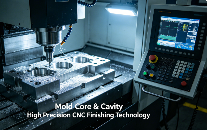
Key Precondition: Eliminate Residual Stress Before Starting Finishing
Most dimensional drift and slow warpage happen long before the finishing pass begins.
Rough milling and quenching lock heavy stress inside hardened mold steel.
If you jump straight into finishing, internal tension will slowly bend the core and cavity after you release the fixture.
Zorapid Pre-Finishing SOP
- After rough milling, run low-temperature aging treatment to release rough-cutting stress.
- Let the insert cool fully to 20°C constant workshop temperature before semi-finishing.
- Leave only 0.15~0.25mm uniform stock across all curved surfaces and shut-off faces. Never leave uneven stock thickness.
- Machine datum planes first to lock stable positioning; avoid re-clamping during finishing cycles.
5-Axis Low-Overhang Tooling to Eliminate Chatter Vibration
Chatter ripples are the No.1 defect on deep mold cavity curved surfaces.
On standard 3-axis mills, you have to use long extended tools to reach deep pocket bottoms.
Long slender tool holders bend and vibrate under cutting load, leaving periodic wave marks on vertical walls.
5-Axis Finishing Solution
- Tilt the spindle or trunnion table to keep the tool short and rigid. Tool overhang can be reduced by 70%.
- Use short shrink-fit holders and variable-pitch AlTiN coated ball end mills designed for hardened steel. Variable pitch flutes break resonance and suppress vibration effectively.
- Keep the tool tip close to the holder; avoid long extension collets at all cost.
Result:
No more fish-scale chatter on deep ribs and contoured curved surfaces. Thin core pins stay straight without bending during high-speed finishing.
Constant Scallop Height 3D Toolpath
Conventional raster parallel finishing creates inconsistent stepover distance on steep curved slopes.
Flat zones have tiny step lines, while steep walls leave wide scallops.
This creates uneven surface texture, requiring heavy hand polishing to level the surface.
Advanced CAM Finishing Strategy We Use Every Day
- Enable constant scallop height in your CAM software. The program automatically adjusts step-over distance according to surface slope. Scallop height stays fixed at 0.002~0.003mm across the entire 3D cavity surface, no matter flat or steep.
- Use spiral 3D offset finishing instead of back-and-forth raster moves. Avoid frequent direction reversal that leaves small stop marks on curved surfaces.
- Add small arc lead-in and lead-out moves at the end of each tool path segment to prevent tiny entry notches.
With this toolpath strategy, the whole cavity gets a consistent fine texture, and you cut polishing workload drastically.
Hard Milling Finishing Parameters For HRC 48~54 Mold Steel
Improper feeds and speeds cause tool burn, surface hardening and uneven material removal.
For hardened mold core and cavity (S136, STAVAX, H13), we strictly follow this finishing parameter set:
- Tool: Ultra-fine grain solid carbide ball mill, TiSiN / AlTiN high-temperature coating
- Spindle SFM: 350 ~ 500, stable high-speed cutting without thermal shock
- Radial stepover: Controlled strictly by constant scallop value, never fixed wide step
- Depth of cut (Z): Light shallow finishing passes, 0.08~0.12mm per cut only
- Cutting mode: Strict climb milling, never conventional up-cutting. Up-cutting creates edge tearing and surface burrs.
Cooling Control Rule
Run through-spindle high-pressure coolant (700+ PSI).
Flush chips continuously out of deep narrow ribs to avoid local overheating and burnt surface layers.
Trapped heat creates a brittle recast layer that ruins surface integrity and long-term mold wear life.
Split Semi-Finish & Finish Passes to Lock Dimensional Stability
One single finishing pass always creates uneven stress on hardened mold inserts.
We split the final machining into two independent light passes to control surface stress:
- Semi-finish pass: Trim stock down to 0.05~0.08mm, stabilize the surface contour, remove most tool load stress.
- Stop the machine and let the part cool completely to ambient temperature.
- Run the final ultra-light finishing cut with minimal material removal.
This two-stage finishing prevents thermal expansion from shifting core and cavity dimensions mid-cut.
Shut-off faces, curved contours and hole positions maintain tight tolerance all the way through.
Zero-Step Machining For Core & Cavity Parting Shut-Off Faces
A small step on the parting line causes plastic flash during injection molding, which is the most common assembly defect.
Most shops machine core and cavity on separate setups, leading to minor datum shift and mismatched shut-off surfaces.
Zero-Step Finishing Process
- Clamp core and cavity inserts on the same zero-point pallet with one unified global coordinate system.
- Machine all mating shut-off faces in the same 5-axis setup without re-fixturing.
- Finish the flat parting plane first before machining curved cavity contours.
- Use light face milling with sharp square end mills to keep shut-off surfaces perfectly coplanar.
We regularly hold parting line mismatch below 0.003mm, eliminating flash issues from poor finishing alignment.
Thermal & Fixture Control To Avoid Post-Finish Deformation
Hardened mold steel expands easily with small temperature changes.
Even 2°C workshop temperature swing will shift the cavity size beyond micron tolerance.
Strict Environmental & Clamping Rules
- Keep the toolroom temperature locked at 20±1°C during all finishing cycles.
- Warm up the CNC spindle for 30 minutes before starting precision finishing to stabilize thermal drift.
- Clamp the insert on a full solid support plate; no overhanging thin sections during final cuts.
- Never release clamps immediately after machining. Let the core & cavity cool slowly while still fixed on the fixture to avoid spring-back deformation.
6 Common Finishing Defects & Shop-Floor Quick Fixes
| Defect | Root Cause | Immediate CNC Correction |
|---|---|---|
| Wave chatter marks on curved cavity walls | Long tool overhang + equal-pitch flute vibration | Switch to 5-axis short rigid tool + variable-pitch ball mill |
| Uneven scallop texture on steep slopes | Fixed stepover raster toolpath | Enable constant scallop height 3D finishing |
| Burnt blue surface on narrow ribs | Poor chip evacuation & insufficient cooling | Activate through-spindle high-pressure coolant |
| Parting line step between core and cavity | Separate clamping setups | Machine mating inserts on one zero-point pallet |
| Core slowly warps after finishing | Unreleased cutting stress | Add semi-finish cooling pause + pre-finish aging |
| Fine tool lines left all over the surface | Frequent toolpath direction reversal | Use continuous spiral offset finishing |
Zorapid Full High-Precision Finishing Workflow For Mold Core & Cavity
Copy this SOP to achieve Ra 0.2~0.4μm CNC surface and ±0.005mm stable tolerance:
- Rough mill → stress relief aging → leave 0.2mm uniform finishing stock
- Machine primary datum planes, clamp on zero-point rigid fixture with full base support
- 5-axis setup with short variable-pitch carbide ball mills, high-pressure through-tool coolant
- Semi-finish pass → pause for full thermal cooling
- Constant scallop height spiral 3D finish with climb milling, light shallow cuts
- Finish shut-off parting faces first to ensure zero-step core-cavity matching
- Keep inserts clamped until fully cooled to room temperature
- 3D CMM inspection on geometry, flatness and surface roughness
Measurable Production Result:
Old 3-axis single-pass finishing: Heavy tool marks, 6~8 hours hand polishing, tolerance drift up to 0.012mm
Optimized 5-axis multi-stage finishing: Near-mirror CNC surface, polishing time reduced by 75%, stable tolerance ≤ ±0.004mm
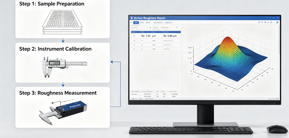
Real EU Client Case Study
A Belgian medical OEM ordered 16-cavity S136 core and cavity inserts.
Their original finishing process had two major quality issues:
- Visible chatter ripples on deep curved cavity walls requiring long manual polishing
- A 0.01mm step appeared on the parting line, causing PEEK part flashing during molding
We upgraded the whole finishing process following our technical standards:
- Switched to 5-axis short rigid tooling to eliminate tool vibration
- Rewrote the CAM program with constant scallop height spiral 3D toolpaths
- Mounted core and cavity on the same zero-point pallet for one-setup shut-off face machining
- Split semi-finish and final finishing with cooling pauses to control residual stress
Final outcome:
Smooth burr-free CNC surface with Ra 0.28μm, parting line mismatch held below 0.0025mm.
Polishing labor was cut dramatically, and the mold ran 1.2 million injection cycles without surface wear or flash.
Conclusion
High-precision CNC finishing for mold core and cavity is not just about running fast spindle speeds.
Stable quality and mirror as-machined surfaces depend on six linked technologies:
- Pre-finish stress relief to stop post-machining warpage
- 5-axis short rigid tooling to eliminate chatter vibration
- Constant scallop height spiral toolpaths for uniform fine texture
- Two-stage semi-finish + ultra-light final hard milling to control surface stress
- Unified zero-point fixturing for zero-step core & cavity shut-off faces
- Strict thermal environment and fixture cooling to lock dimensional stability
If you master these steps, you can get SPI Class A surface directly off the CNC machine and drastically cut bench polishing time.
At Zorapid, we deliver high-precision hard milling finishing for hardened mold core and cavity inserts across medical, automotive and consumer injection molds for clients all over Europe and North America.
If you keep fighting chatter marks, uneven tool lines and parting line mismatch, send your 3D model and material grade. Our CNC programmers will build a full toolpath, tooling and finishing parameter plan for your next mold project.
FAQ
Can I reach SPI Class 101 surface directly from CNC hard milling?
With constant scallop finishing and sharp coated ball mills, we consistently hit Ra 0.2~0.4μm. Only minor buffing is needed, removing 70% of traditional hand polishing work.
Why does the mold cavity warp only after finishing is fully completed?
Heavy single-pass finishing locks high tensile stress inside hardened steel. Splitting the cut into semi-finish + finish with cooling pauses releases tension gradually and prevents delayed bending.
Is constant scallop finishing better than fixed stepover raster milling?
Yes. Fixed stepover creates wide scallops on steep curved walls. Constant scallop automatically adjusts step distance to keep surface texture consistent on flat and curved geometry.
Can I finish core and cavity on separate 3-axis setups without a parting line step?
It is very hard to hold zero-step matching. Even small re-clamp offset creates a visible shut-off mismatch. One unified 5-axis zero-point setup remains the most reliable solution.


