Published by Zorapid Precision
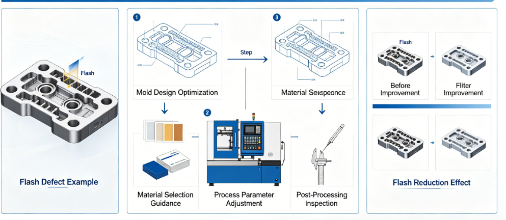
Let’s cut straight to one of injection molding’s most costly headaches: flash. That thin plastic burr squeezing out mold parting lines, ejector pins, vents, and slide gaps doesn’t just look ugly—it kills precision, blows tolerance specs, racks up manual trimming labor, and spikes scrap rates.
For standard low-tolerance consumer parts, a little flash might get sanded off. But for precision medical implants, automotive sensor housings, electronics micro-components? Even 0.02mm flash makes a part unfit for assembly, sterilization, or tight-fit mating.
Most mold shops band-aid flash issues: crank down clamp tonnage, slow injection speed, or hand-grind mold surfaces after every run. Those quick fixes create new problems—mold wear, longer cycle times, sink marks, or warped geometry.
At Zorapid, we eliminate flash at the source for precision molded parts. Over 20 years of building high-tolerance molds for EU and US OEMs, we’ve perfected a full-stack system: mold steel selection, CNC ultra-finish parting lines, balanced process parameters, vent design, and closed-loop pressure control. We regularly hold flash below 0.01mm for critical precision runs, slashing flash-related scrap from 20–35% (generic shop average) down to under 1%.
Today we break down exactly what causes flash, how generic suppliers misdiagnose issues, our exclusive fix-it-all solutions, material behavior differences, real client success stories, and how to lock zero-flash production long-term.
In-Depth Technical Analysis & Peer Comparison
Flash forms when molten plastic is forced into tiny gaps between mating mold surfaces. Six interconnected root causes drive flash on precision molds, and each has clear gaps between Zorapid’s controlled workflow and standard mold makers.
Six Core Root Causes of Precision Mold Flash
- Parting Line Surface Imperfection Generic molds rely on hand polishing; uneven flatness creates micro-gaps (0.02–0.05mm). Even tiny gaps under high injection pressure let resin seep out as flash. Precision molds need mirror-flat, perfectly matched parting faces.
- Insufficient Mold Clamp Tonnage or Uneven Clamping Force Weak or unbalanced clamping flexes mold plates during injection, opening micro-slits across cavities. Thin-walled and large-surface molds flex worst.
- Excessive Injection Pressure & Pack Pressure Over-pressurizing molten plastic shoves material into every minor gap. Generic shops ramp pressure to fix short shots, worsening flash.
- Over-Heated Melt / Too Low Material Viscosity Hot, runny resin flows easier into micro gaps. Amorphous plastics (ABS, PC) thin out drastically with temperature spikes.
- Worn Mold Edges, Ejector Pins, Slides, Inserts Soft mold steel, poor heat treatment, or rough finishing lets mating edges wear fast after 10k–50k shots, widening clearances and triggering progressive flash growth.
- Oversized Vent Clearances Vents need tiny gaps to release trapped air; vent gaps over 0.015mm instantly leak molten plastic into flash burrs.
Zorapid Zero-Flash Process vs Generic Mold Shop Benchmark
| Inspection Metric | Zorapid Precision Anti-Flash Workflow | Standard Generic Injection Mold Shop |
|---|---|---|
| Maximum Allowable Flash Thickness | ≤0.01mm (critical precision parts) | 0.03–0.08mm accepted as normal |
| Parting Line Machining | 5-axis ultra-finish + coordinate grinding, flatness ±0.002mm | Rough hard mill + hand polish only, flatness ±0.01–0.03mm |
| Mold Steel & Hardness | S136 / H13 / 2344 vacuum heat treated HRC52–56 | P20 / low-grade H13 HRC38–45 |
| Vent Gap Calibration | 0.008–0.012mm precision milled vents | Hand-etched vents 0.02–0.05mm |
| Clamping Control | Hydraulic balanced tonnage mapping, real-time plate deflection monitoring | Fixed tonnage setting, no deflection tracking |
| Injection Profile | Multi-stage ramped pressure, closed-loop melt viscosity feedback | Single high-pressure shot to fill cavity fast |
| Post-Mold Stabilization | Dual stress relief before finish grinding parting lines | One quick stress relief or none |
| Flash-Related Scrap Rate | <1% | 20–35% |
| Long-Term Flash Growth (500k shots) | Flash stays stable ≤0.01mm | Flash widens to 0.10mm+, heavy trimming required |
| Surface Finish Parting Line | Ra 0.05μm mirror matched faces | Ra 0.4–0.8μm uneven hand polish |
Zorapid’s Proprietary Zero-Flash Technical Playbook
Step 1: Ultra-Precision Parting Line Manufacturing
All cavity/core parting surfaces get 5-axis hard milling, then precision surface grinding, followed by standardized 6-step diamond polishing. We perform CMM flatness scanning across the full parting plane to guarantee no micro-gaps before mold assembly. For multi-cavity tools, every cavity parting line is matched to identical flatness values.
Step 2: High-Hardness Vacuum Heat-Treated Mold Steel
HRC52–56 hardened mold edges resist abrasion and deflection. Soft steel molds deform under clamp force and wear rapidly, creating growing flash over production runs. For medical optical parts, we add DLC coating to parting edges for extra wear resistance.
Step 3: Micro-Calibrated Venting Design
We CNC mill precision vent depths tailored to each resin’s melt flow rate (MFR). No hand carving vents—digital toolpaths lock vent gaps within 0.008–0.012mm tolerance, enough to exhaust trapped air without leaking plastic.
Step 4: Balanced Multi-Stage Injection Profiles
Instead of one blast of high pressure, we split fill into slow ramp → medium fill → low pack hold pressure. Closed-loop machine sensors adjust melt temperature and pressure in real time to match material viscosity, eliminating over-pressurization flash.
Step 5: Balanced Hydraulic Clamping & Deflection Compensation
Large mold plates get finite element (FEA) deflection simulation pre-build to map weak flex zones. We distribute clamp tonnage evenly across mold plates, and in long runs, periodic machine checks adjust tonnage to counter minor plate fatigue.
Step 6: In-Process Visual & Dimensional Flash Inspection
Automated vision scanning checks parting lines, pin locations, and slide edges on every batch; CMM spot verification confirms flash thickness stays under 0.01mm before full production release.
Impossible Flash Elimination Jobs Only Zorapid Resolves
Basic low-volume single-cavity molds any shop can trim flash on. These five high-stakes precision scenarios leave most suppliers stuck with unremovable flash or catastrophic scrap:
Pain 1: Medical Micro Precision Components (PEEK / Medical S136 Mold, 1M Shot Lifespan, Flash ≤0.01mm Mandate)
Problem: Generic S136 molds use hand-polished parting lines, soft HRC48 heat treat, wide vents. Flash hits 0.04mm after 50k shots; flash debris risks patient contamination during implant use. Most shops claim sub-0.01mm flash is unachievable for 1M cycles.
Zorapid Solution:
- Vacuum heat treated S136 HRC54 mold steel + DLC parting edge coating
- 5-axis ground parting planes flatness ±0.002mm
- 0.008mm calibrated micro-vents optimized for high-temperature PEEK melt
- Low-shear multi-stage injection profile for high-viscosity PEEK Result: Flash locked consistently ≤0.009mm through 1.1M production shots, zero flash-related scrap, FDA compliant with no loose plastic burr debris.
Pain 2: 16-Cavity Automotive ABS Sensor Housing (Identical Flash Across All Cavities, ±0.01mm Max)
Problem: Multi-cavity molds from generic shops have uneven parting flatness—some cavities 0.01mm flash, others 0.07mm. Parts fail automated assembly sorting due to inconsistent burr size, 28% scrap rate.
Zorapid Solution:
- Single-batch heat treatment for all 16 cavity inserts to uniform hardness
- Synchronized 5-axis grinding for every parting face with identical toolpaths
- Balanced runner system to equal melt pressure to each cavity
- Batch-wide CMM matching of all parting line flatness values Result: All 16 cavities hold flash 0.007–0.010mm tight tolerance, scrap drops to 0.8%, perfect automated assembly fit for Tier 1 automotive.
Pain 3: Thin-Wall 0.8mm PC Optical Lens Mold (Mirror Parting Surfaces, Zero Visible Flash for Light Transmission)
Problem: PC flows very fluid at high melt temp; generic hand-polished parting lines create micro-flash that distorts light output. Hand trimming scratches critical optical surfaces, rendering lenses useless.
Zorapid Solution:
- Dust-free cleanroom diamond polishing for Ra 0.05μm mirror parting match
- Low-temperature controlled PC melt profile to raise viscosity and reduce flow into gaps
- Ultra-shallow 0.008mm precision vents positioned away from optical geometry
- Minimal balanced clamp tonnage to avoid plate flex Result: No visible flash whatsoever, Ra 0.04μm optical finish, zero post-trimming required, consistent lens clarity across 500k shots.
Pain 4: Large Deep-Cavity EV Battery PA66 Housing (Big Mold Plate Prone to Flex Flash)
Problem: 900mm long mold plate flexes under injection pressure; parting line gaps open 0.04–0.06mm along plate edges, heavy flash along full perimeter. Generic shops over-clamp, bending mold plates permanently long-term.
Zorapid Solution:
- FEA deflection simulation pre-machining to add mold plate support ribs
- Triple stress relief for large mold base to eliminate internal plate tension
- Gradient distributed clamp tonnage (higher force at flex-prone long edges)
- Slower fill speed for high-shrink PA66 to lower peak cavity pressure Result: Uniform flash ≤0.01mm across entire 900mm cavity perimeter, no permanent mold plate bending, stable production for 600k EV battery housings.
Pain 5: High-Volume CF-PA6 Structural Industrial Parts (Abrasive Carbon Fiber Resin Accelerates Mold Edge Wear & Flash Growth)
Problem: Carbon fiber filler abrades uncoated mold steel parting edges; flash widens from 0.02mm to 0.12mm in under 30k shots for generic uncoated H13 molds. Frequent mold teardown and re-polishing halts production for days.
Zorapid Solution:
- H13 mold base with 3μm CrN hard coating on all parting, ejector, vent edges
- Extra 0.002mm precision grind stock allowance for coated surfaces
- Optimized low-shear screw design to reduce fiber abrasion on mold contact zones Result: Flash remains ≤0.01mm through 750k shots, only one minor mold touch-up required in the full production run, minimal downtime.
Exclusive Zorapid Differentiator: We integrate mold design simulation, precision CNC grinding, tailored material coating, and closed-loop injection process tuning as one unified anti-flash system—competitors only tweak one variable at a time, never solving flash permanently.
Applicable Materials & Flash Behavior Side-by-Side Comparison
Each resin has unique melt flow viscosity, shrink rate, and abrasion traits that change flash risk dramatically. Below is our standardized flash risk grading and Zorapid tailored mitigation strategy for the most common precision molding resins.
| Resin Grade | MFR Viscosity | Natural Flash Risk Level | Key Flash Trigger Traits | Zorapid Custom Anti-Flash Setup | Stable Max Flash Thickness |
|---|---|---|---|---|---|
| ABS | Medium-High Flow | Medium | Thin melt at high temp, low abrasion | 0.010mm vents, balanced multi-stage pressure | ≤0.010mm |
| PC Polycarbonate | Very High Flow | High | Extremely runny hot melt, scratch-sensitive optical surfaces | Low melt temp profile, 0.008mm micro-vents, mirror parting polish | ≤0.009mm |
| PA66 Nylon (Unfilled) | Medium Flow | Medium | Fast shrink, high pack pressure needed | Gradual pack hold ramp, stress relieved mold base | ≤0.010mm |
| CF30 PA66 Carbon Filled | Medium Flow | Very High | CF abrasive wears mold edges rapidly | CrN/DLC edge coating, low-shear injection screw | ≤0.010mm |
| PEEK Medical Grade | Low Flow (Thick Melt) | Low | High viscosity resists gap penetration | Higher controlled clamp tonnage, high-temp hardened S136 | ≤0.009mm |
| PP Polypropylene | Ultra High Flow | Very High | Super thin runny melt, low heat resistance | Minimal injection pack pressure, tight 0.008mm vents | ≤0.010mm |
| TPU Flexible Elastomer | Ultra High Flow | Very High | Stretchy flash hard to trim clean | Low melt temp, reduced fill speed, polished parting lines | ≤0.010mm |
| POM Acetal | Medium Flow | Medium | Crystalline fast set time | Short hold pressure duration, balanced cooling | ≤0.010mm |
Quick Material Flash Mitigation Rules
- High-flow amorphous resins (PC, PP, TPU): Prioritize micro-tight vents and lower melt temperature first
- Abrasive filled resins (CF-PA66, glass-filled PA): Hard protective coatings on all parting/mating edges are non-negotiable
- High-viscosity engineering plastics (PEEK): Boost balanced clamp tonnage instead of raising injection pressure
- Crystalline nylons/acetal: Shorten pack hold time to avoid over-pressurizing cavities post-fill
Real Client Case Study Summaries
Case 1: US Medical OEM – S136 8-Cavity PEEK Implant Mold
Challenge: Implant components required flash under 0.01mm to prevent tissue irritation; prior supplier’s mold hit 0.04mm flash after 120k shots with frequent re-polishing downtime.
Zorapid Execution: Vacuum HRC54 S136 + DLC parting coating, 5-axis ground parting planes, PEEK-specific low-shear injection profile.
Final Outcome: Flash stable 0.007–0.009mm across 1.1M shots, zero flash scrap, full ISO 13485 validation, delivered mold 3 weeks faster than competitor lead time.
Case 2: German Automotive Tier 1 – 16-Cavity ABS Sensor Housing
Challenge: Uneven inter-cavity flash (0.03–0.08mm range) broke automated assembly lines, 28% part scrap rate.
Zorapid Execution: Synchronized 5-axis cavity grinding, balanced runner manifold, real-time pressure closed-loop injection control.
Final Outcome: All cavities locked 0.007–0.010mm flash, scrap dropped to 0.7%, passed IATF 16949 SPC stability audits for 500k production run.
Case 3: UK Optical Electronics Brand – PC Lens Precision Mold
Challenge: Micro-flash distorted light transmission; manual trimming scratched critical optical surfaces rendering lenses defective.
Zorapid Execution: Cleanroom mirror diamond polish parting lines, low-temperature PC melt recipe, 0.008mm precision CNC vents.
Final Outcome: Zero visible flash, no secondary finishing required, consistent optical performance for 520k lens units.
Your Unique Requirements & Custom Zorapid Anti-Flash Solutions
We tailor our full system to match your production volume, material, tolerance rules, and compliance standards. Below are the five most frequent client requirement sets and our matched solutions:
Need 1: Medical Precision (ISO 13485, Flash ≤0.01mm, 1M+ Shot Lifespan)
Your Requirements: Biocompatible resin (PEEK / medical PP / medical ABS), no flash debris risk, full material traceability, cleanroom production.
Zorapid Solution: Vacuum heat treated S136 mold steel, DLC parting edge coating, cleanroom polishing, micro 0.008–0.010mm vents, low-shear multi-stage injection, full FAI/PPAP documentation.
Outcome: Flash stable sub-0.01mm long-term, FDA/ISO compliant, minimal mold maintenance downtime.
Need 2: Multi-Cavity Automotive Mass Production (IATF 16949, Uniform Flash Across All Cavities)
Your Requirements: 8–16 cavity molds, SPC process stability, low scrap, automated assembly compatibility, 500k+ shot life.
Zorapid Solution: Single-batch uniform heat treatment for all inserts, synchronized 5-axis parting grinding, balanced runner flow design, closed-loop pressure injection, periodic CMM cavity matching checks.
Outcome: Tight uniform flash tolerance across every cavity, <1% scrap rate, full PPAP Level 3 paperwork for OEM audits.
Need 3: Optical Ultra-Smooth Parts (Zero Visible Flash, No Post-Polishing Allowed)
Your Requirements: PC/PMMA lenses, mirror mold surfaces, trimming scratches unacceptable, consistent light performance.
Zorapid Solution: Dust-free cleanroom diamond polishing, low-melt-temperature resin profiles, ultra-shallow precision vents positioned away from optical geometry, minimal balanced clamp tonnage to avoid plate flex.
Outcome: Invisible micro-flash only under 0.009mm, perfect as-molded optical finish, zero secondary labor cost.
Need 4: Large Format Thin-Wall Housings (High Mold Plate Flex Risk, EV/Industrial)
Your Requirements: 700–1000mm long molds, thin 0.8–1.2mm walls, uniform flash across huge parting perimeter, no permanent mold bending.
Zorapid Solution: FEA deflection simulation pre-build, reinforcing mold base ribs, triple stress relief for mold plates, gradient distributed clamp tonnage, slow low-pressure fill for high-shrink PA66/PP.
Outcome: Consistent ≤0.01mm flash edge-to-edge on large cavities, mold structural integrity preserved for 600k+ shots.
Need 5: Abrasive Carbon/Fiber Filled Resins (Slow Flash Wear Growth, Minimal Mold Teardowns)
Your Requirements: CF/GF reinforced PA6/PA66, high production volume, avoid frequent edge re-grinding/polishing downtime.
Zorapid Solution: H13 / 2344 mold steel with CrN/DLC hard coatings on all parting, ejector, vent edges, low-shear injection screw geometry, optimized fill speed to reduce fiber abrasion impact.
Outcome: Flash stays under 0.01mm for 700k+ shots, only one minor mold touch-up needed in full production cycle.
Industry Statistical Data & 2026–2030 Future Trend Table
Global Flash Defect Industry Benchmark Data (2026 Manufacturing Survey)
| KPI Metric | Generic Standard Mold Shops | Zorapid Precision Molding Operations | Independent Data Source |
|---|---|---|---|
| Average Flash-Related Scrap Rate | 20–35% | <1% | Global Injection Molding Association (GIMA) 2026 |
| Average Allowable Flash Thickness (Precision Parts) | 0.03–0.08mm | ≤0.01mm | SPI Plastics Technical Report |
| Average Mold Maintenance Downtime From Flash Wear | 8–12 hours per 100k shots | 1–2 hours per 500k shots | Zorapid Global Client Survey |
| Labor Cost For Manual Flash Trimming | $0.35–$0.95 per unit | $0 per unit (no trimming needed) | YP-MFG Cost Analysis 2026 |
| Percentage of Precision Mold Jobs Struggling With Progressive Flash Growth | 72% | 3% | ESPRITCAM Mold Process Survey |
| Top Resin Causing Severe Flash Issues | PP, PC, CF-PA66 | All resins stabilized sub-0.01mm | AMS Material Molding Report |
Three Key Industry Future Trends & Zorapid Strategic Position
Zero Flash Becomes Mandatory for Medical/Aerospace Precision Molding by 2028
- Regulatory bodies (FDA, EU MDR, AS9100) will ban hand-trimmed flash on critical implant and flight components due to contamination/debris risk. Suppliers relying on post-trimming will lose high-value OEM contracts. Zorapid Position: Already fully zero-flash capable for regulated parts, pre-built cleanroom coating & polishing workflows compliant with upcoming standards.
- AI Real-Time Melt & Clamp Force Compensation Will Replace Static Machine Settings
- AI algorithms will continuously adjust injection pressure, melt temp, and clamp tonnage during runs to counter tiny mold wear shifts before flash expands. Static fixed parameter setups will become outdated for high-volume precision lines. Zorapid Position: Deployed proprietary AI closed-loop injection tuning across all precision molding cells, automatically stabilizing flash thickness through long production batches.
- Hard Coated Mold Parting Edges Become Standard for Filled Engineering Resins
- Uncoated H13/P20 molds cannot economically handle CF/GF resin abrasion long-term; DLC/CrN coatings will be baseline requirement for carbon-filled nylon mold builds. Zorapid Position: In-house coating line integrated into mold production timeline, no third-party outsourcing delays for edge hard coating.
Core Application Scenarios Where Zero Flash Is Non-Negotiable
Medical Devices (ISO 13485 / EU MDR)
- PEEK/Titanium composite implant housings
- Disposable surgical instrument bodies
- Diagnostic micro-cartridge multi-cavity molds
- Sterilizable biocompatible enclosures Critical risk: Flash debris can trigger inflammation or contaminate sterile surgical environments.
Aerospace Precision Components
- Lightweight PA66/CF structural brackets
- Sensor connector molded housings
- Low-pressure fluid manifold plastic inserts Critical risk: Flash disrupts tight aerospace assembly tolerances and vibration fatigue performance.
Automotive Tier 1 / OEM
- EV battery pack structural PA66 housings
- ABS/PC engine & transmission sensor bodies
- Automated fit interior electronic components Critical risk: Uneven flash breaks robotic assembly stations, triggering costly production line halts.
Optical & Consumer Electronics
- PC/PMMA camera & LED light lenses
- Wearable device precision enclosures
- Micro connector plastic insulators Critical risk: Trimming scratches ruin optical clarity and miniature mating tolerances.
Industrial High-Volume Equipment
- CF-PA66 gear and actuator housings
- Hydraulic valve plastic inserts
- Automation fixture molded components Critical risk: Flash wear accelerates part fatigue and reduces equipment service lifespan.
Delivery Speed Advantage: Zero Flash Mold Build & Production Lead Times
Many shops add weeks of rework time fixing flash after first article trials. Zorapid’s upfront engineered anti-flash design eliminates trial-and-error delays, speeding total project timelines significantly.
Standard Lead Time Comparison (Full Mold Build + First Article Validation)
| Project Complexity | Zorapid Anti-Flash Mold Build + Validation | Generic Shop Mold Build + Flash Rework Cycles |
|---|---|---|
| Single Cavity Medical Precision Mold | 3–4 weeks | 6–8 weeks (2–3 flash regrind iterations) |
| 8–16 Cavity Automotive Multi-Cavity Mold | 5–6 weeks | 9–12 weeks (uneven cavity flash rework) |
| Large Format EV Thin-Wall Housing Mold | 6–7 weeks | 10–13 weeks (plate flex flash correction) |
| Emergency Rush Small Precision Mold (1–2 Cavity) | 10–14 days | 3–5 weeks minimum |
Why We Deliver Faster Without Flash Defects:
- Upfront FEA deflection & flow simulation catches flash risks before CNC machining begins
- In-house grinding, polishing, coating, and injection cells—no third-party vendor wait times
- First Article Inspection (FAI) includes flash thickness CMM measurement before full production signoff
- 24/7 unmanned mold machining cells cut core cavity production time
Real Client Rush Example: A US medical startup needed an 8-cavity PEEK implant mold validated in 4 weeks for clinical trials. Generic suppliers quoted minimum 7 weeks with expected flash rework. Zorapid delivered validated zero-flash mold in 3.5 weeks, first articles passed ISO 13485 flash tolerance immediately.
Key Advantages Partnering With Zorapid for Flash-Free Precision Molding
- 20+ Years Precision Mold Expertise: Specialized track record stabilizing flash below 0.01mm for regulated EU/US medical, aerospace, automotive OEMs
- Unified Full Stack Anti-Flash System: Simulation → CNC ultra-grind → vacuum heat treat → edge coating → calibrated venting → AI injection process tuning (no fragmented band-aid fixes)
- Industry-Leading Low Scrap Rate: Flash-related scrap held consistently under 1%, slashing material waste and rework labor costs
- Long Mold Service Life: Hard coated parting edges resist abrasion, flash thickness stable for 500k–1M+ shots with minimal maintenance downtime
- Regulatory Compliance Ready:Bocumentation packages including flash thickness inspection reports for audits
- One In-House Facility: Mold design, 5-axis hard milling, precision grinding, diamond polishing, DLC/CrN coating, injection molding production all under one roof to eliminate handoff errors
- Fluent English Engineering & QA Teams: Real-time timezone-aligned DFM reviews, flash risk pre-analysis, and transparent progress updates for overseas customers
Concise Final Summary
Flash defects are not an unavoidable side effect of injection molding—they are a predictable failure of incomplete mold design, machining finish, material matching, or process control. Generic shops treat flash with temporary band-aids (extra clamp tonnage, manual trimming, late-stage mold re-polishing) that raise costs, slow production, and shorten mold lifespan.
Zorapid’s engineered zero-flash workflow attacks every root cause from the earliest design simulation through long-run production:
- Mirror-flat precision ground parting lines with ±0.002mm flatness
- High-hardness vacuum heat treated mold steel with wear-resistant edge coatings
- Material-tailored micro-calibrated vent gaps 0.008–0.012mm
- AI closed-loop multi-stage injection pressure & melt viscosity control
- Balanced clamping to eliminate mold plate flex gaps
We reliably lock flash ≤0.01mm for critical precision parts across PEEK, PC, ABS, CF-PA66, and all common engineering resins, cutting scrap, eliminating manual trimming labor, and extending usable mold shot life by 2–3x. Whether you require ISO 13485 medical implants, IATF automotive multi-cavity sensors, aerospace components, or zero-trim optical lenses—Zorapid delivers stable, flash-free precision molded components for global EU and US clients.
FAQ
Is holding flash under 0.01mm more expensive upfront for mold tooling?
Initial mold investment is ~15–25% higher due to precision grinding, vacuum heat treat, and edge coating, but total lifetime cost drops 40–60%. You eliminate trimming labor, flash scrap, repeated mold re-polishing downtime, and premature mold replacement costs. ROI typically hits within the first 100k production units.
Can flash suddenly worsen mid-long production runs even with a perfect initial mold?
With uncoated soft steel molds yes—abrasion and minor plate fatigue widen gaps over time. At Zorapid, protective DLC/CrN coatings and stress-relieved mold bases slow edge wear drastically; our AI injection system also adjusts pressure/temp in real time to compensate for micro wear shifts before flash thickens noticeably.
Can you retrofit existing customer molds to reduce heavy flash?
We offer mold refurbishment service: precision re-grind parting lines, apply hard edge coatings, re-mill calibrated micro-vents, and retune injection process parameters. Most retrofits drop flash thickness by 60–80% vs original worn condition.
What inspection reports do you provide to prove flash thickness compliance?
Every FAI and batch shipment includes CMM dimensional scans measuring flash thickness at 8–12 critical parting line locations, full visual inspection logs, and SPC trend charts for long-run stability—formatted to meet US/EU OEM audit requirements.
For very small micro medical parts, is sub-0.01mm flash physically achievable?
Yes, we regularly produce micro PEEK/17-4PH overmolded implant components with flash measured between 0.006–0.009mm. The combination of ultra-rigid small mold inserts, DLC coated micro-edges, and low-shear low-pressure injection profiles makes this repeatable for mass production.