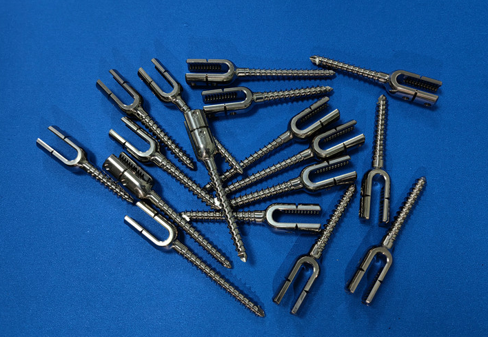
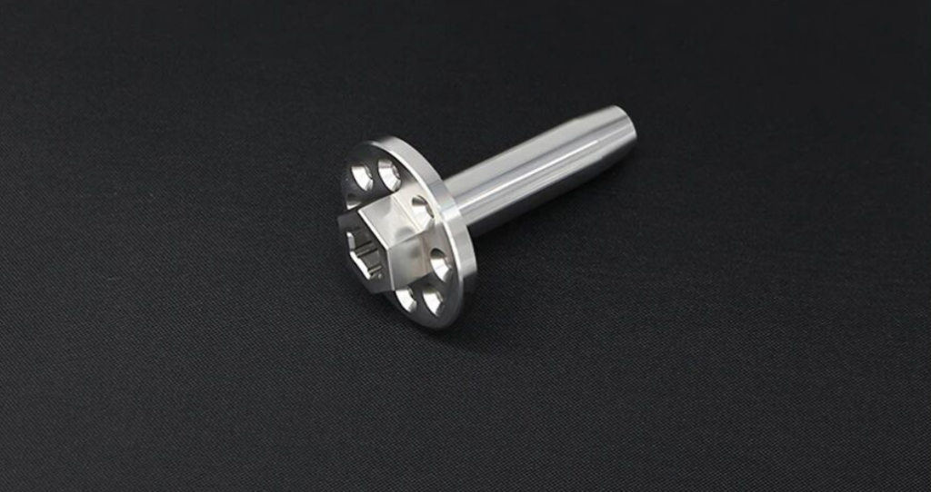
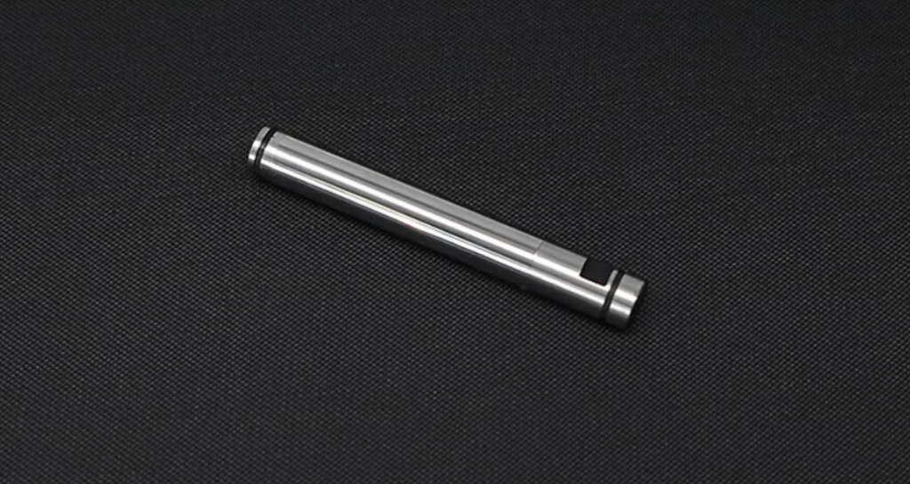
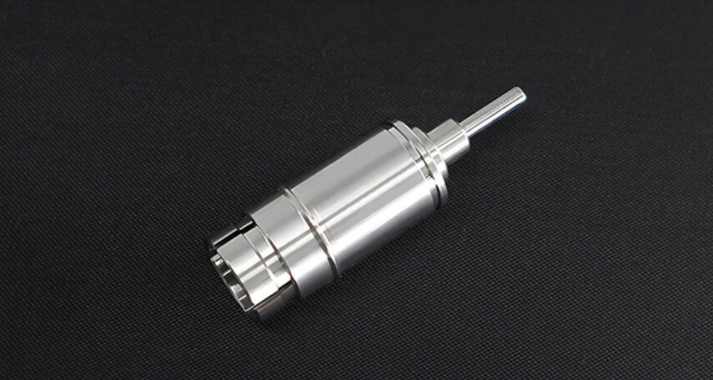
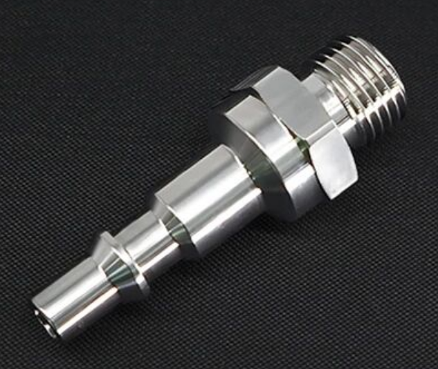
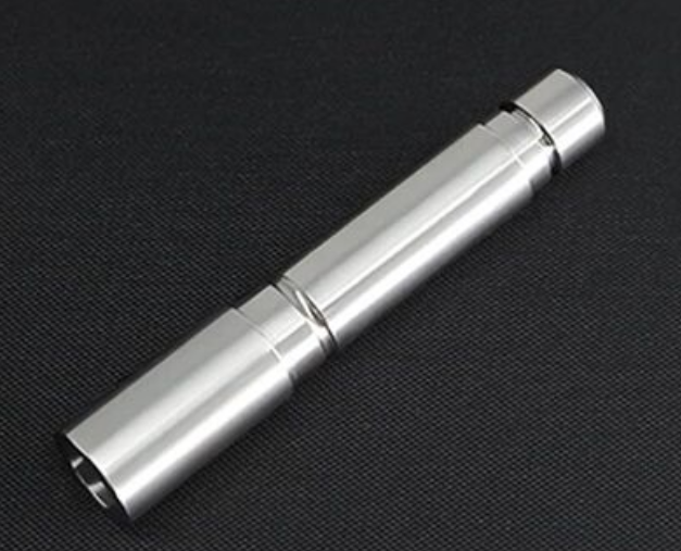
Shaft parts are a common type of mechanical component with a rotary structure. Generally longer in length than diameter, they are widely used in various mechanical equipment to support transmission components, transmit torque and bear loads.
Technical Requirements for Shaft Parts Machining
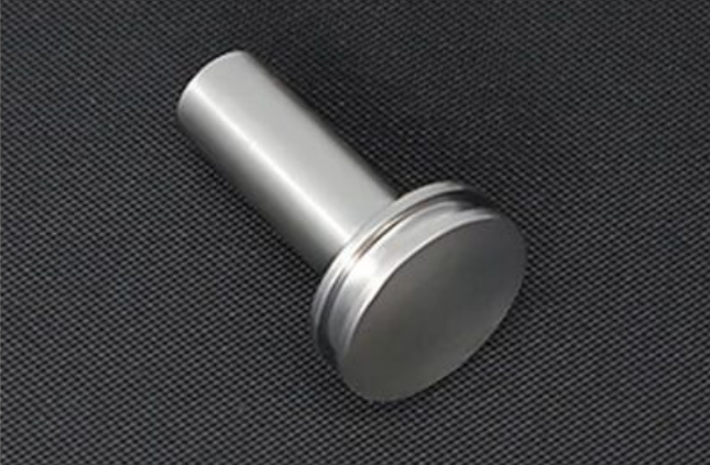
Dimension Accuracy:The main surfaces of shaft parts are generally divided into two categories. The first type refers to the outer circular journals fitted with bearing inner races, namely supporting journals. They determine and support the shaft position and require high dimensional accuracy, usually ranging from IT5 to IT7. The second type are mating journals for assembling various transmission components, with slightly lower precision, commonly specified as IT6 to IT9.
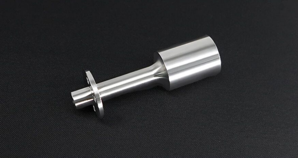
Geometric Shape Accuracy:Roundness and cylindricity of critical surfaces such as journal surfaces, outer conical surfaces and tapered holes. Their errors shall generally be limited within the dimensional tolerance range. For precision shafts, additional specifications on geometric shape accuracy shall be indicated separately on the part drawing.
Mutual Position Accuracy:Coaxiality of outer surfaces and critical shaft surfaces, radial runout of circles, perpendicularity of key end faces to the shaft centerline, parallelism between end faces, etc.
Surface Roughness:All shaft machined surfaces require specified surface roughness, determined by process feasibility and cost. Support journals: Ra 0.2~1.6 μm; transmission fitting journals: Ra 0.4~3.2 μm.
Requirements for heat treatment, chamfering, edge breaking and surface finishing.
Machining Process of Shaft Parts
Basic Principles of Machining Process Formulation
Machining shall be performed first at positions close to the tool setting point, followed by positions far from the tool setting point. Arrange rough machining for internal and external surfaces first, and then carry out finish machining. Simplify the program flow to reduce error risks and improve programming efficiency.
Division of Processes:Divide one clamping and machining operation into a single process, which applies to parts with limited machining content.Divide processes by the machining content completed with the same cutting tool.Divide processes by machining positions, suitable for workpieces with a large amount of machining content.
Clamping Method:
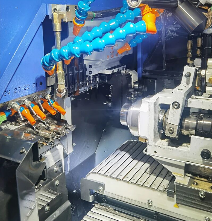
The general fixture of CNC lathes is the chuck, mostly a three-jaw chuck. When machining shaft parts with a three-jaw chuck, the axis of the workpiece coincides with the center line of the chuck. Alignment is usually unnecessary, featuring fast clamping efficiency.
High-precision parts use the following machining methods
Double center clamping:
Suitable for long workpieces or parts requiring multiple clampings, such as long shafts and lead screws. It features easy operation, no alignment needed and high clamping accuracy. However, center holes must be drilled on the workpiece end faces before clamping.
Single chuck and single center mounting
Double-center clamping features high accuracy but low rigidity, restricting cutting parameters. For common shafts and heavy workpieces, adopt one-end clamping plus tail center support.
The center hole of shaft parts serves as the design datum, machining datum and inspection benchmark for qualification evaluation. Thus, center holes are critically important, whose angle, roundness and surface roughness must meet specified precision requirements.