
Publisher: Zorapid.Ltd
Designing custom sheet metal brackets feels straightforward — until your first batch arrives and mounting holes no longer line up, flanges won’t sit flat, and assembly crews waste hours forcing parts together.
We run a 3,000㎡ precision sheet metal workshop at Zorapid. Every month we review hundreds of bracket DXF and STEP files from Europe and North America.
80% of assembly failures come down to one simple problem: poorly defined tolerances.
Two costly scenarios repeat nonstop:
- You write zero tolerance notes on the drawing. The fabricator uses loose commercial standards, and your brackets fail alignment.
- You lock every single dimension to ±0.05mm. Production slows, inspection work explodes, and your part cost jumps 35% for zero real functional benefit.
This is a fully practical tolerance reference built exclusively for custom sheet metal brackets. We break down laser cutting, CNC bending, hole positioning, flatness, and GD&T rules based on ISO 2768 international standards.
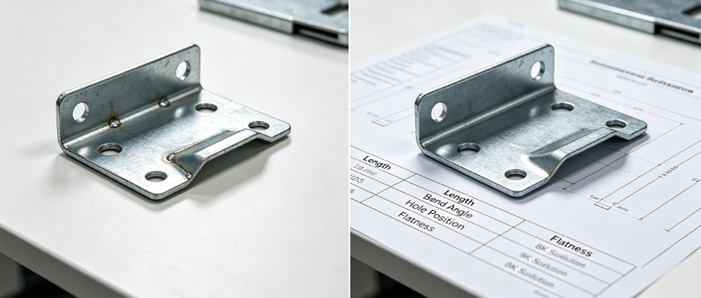
What Makes Sheet Metal Brackets So Tricky for Tolerance Control?
Brackets always combine multiple processes: fiber laser cutting, CNC press brake bending, hole punching, tapping, and welding. Every step adds minor dimensional variation.
Three unavoidable manufacturing variables shift your finished size:
- Material springback Aluminum, stainless steel, and high-strength carbon steel bounce back after bending. Even identical programs produce slight angle shifts.
- Bend deduction stack-up Each fold adds cumulative error. 3 or 4 bends on a simple L-bracket multiply small deviations into big alignment gaps.
- Thermal deformation during cutting Laser heat warps thin sheets. Thin 1.0mm aluminum brackets will lose flatness if tolerance rules do not account for heat distortion.
Flat plate cutting alone is easy. Once you add folded flanges, holes near bend lines, and mounting slots, your tolerance rules need strict process-based limits.
Base Standard
Nearly all industrial sheet metal shops worldwide follow ISO 2768-1 as the default tolerance rule unless you specify otherwise.
Zorapid strictly uses ISO 2768-m (medium grade) as our baseline for all standard brackets. We split tolerances into three tiers for bracket projects:
- Coarse (c): Low-cost non-structural mounting brackets
- Medium (m): Standard industrial equipment brackets (90% of our customer orders)
- Fine (f): Precision positioning brackets for automation, semiconductor and automotive assemblies
Linear Dimension Tolerance Table (Bracket Overall Length & Flange Sizes)
| Nominal Dimension (mm) | Coarse ± (mm) | Standard Medium (m) ± (mm) | Precision Fine (f) ± (mm) |
|---|---|---|---|
| 0 ~ 30 | 0.30 | 0.20 | 0.10 |
| 30 ~ 120 | 0.60 | 0.30 | 0.15 |
| 120 ~ 400 | 1.00 | 0.50 | 0.25 |
| Over 400 | 1.50 | 0.80 | 0.40 |
Quick rule from our engineering team:
Only mark tight fine-grade tolerance on critical mounting dimensions. Leave non-critical outer profiles at medium grade to cut cost and lead time.
Breakdown — Tolerance Reference For Every Bracket Feature
This is the core checklist you can paste directly into your drawing notes. We split each feature into standard commercial tolerance and precision tight tolerance, tested on thousands of Zorapid bracket jobs.
1. Laser Cut Outer Profiles (Blank Flat Pattern)
- Standard Tolerance: ±0.15 ~ ±0.20 mm
- Precision Grade (thin sheet <3mm): ±0.05 ~ ±0.10 mm
- Limit: Laser cutting cannot hold ±0.03mm consistently on steel thicker than 6mm due to beam kerf deviation.
2. CNC Bending (Biggest Source of Bracket Errors)
Bend tolerance directly controls flange flatness and hole alignment after folding.
| Bending Feature | Standard Commercial Tolerance | Precision Bending (With Angle Compensation) |
|---|---|---|
| Bend Angle | ±1.0° | ±0.5° (requires coining tooling) |
| Flange Length (Bend Position) | ±0.30 mm | ±0.15 mm |
| Cumulative Size After Multiple Bends | Total ±0.5~0.8 mm | Total ±0.3~0.5 mm |
Key note: Stainless steel and spring steel have stronger springback. Always relax bend angle tolerance by 0.5° compared to mild SPCC carbon steel.
Hole & Slot Tolerance (Most Critical For Bracket Assembly)
Mounting holes decide whether your bracket bolts line up perfectly. We separate common holes into two categories:
A) Regular Bolt Clearance Holes
- Hole diameter: +0.2 ~ +0.4 mm
- Hole-to-hole center distance: ±0.20 mm (standard) / ±0.10 mm (precision positioning)
- Hole to bend line: Minimum 2.5 × material thickness to stop hole deformation during folding. If you place holes closer, we have to relax position tolerance.
B) Dowel Pin Locating Holes (High-precision fixtures)
- Hole size tolerance: ±0.05 mm
- Position GD&T: True Position 0.1mm @ MMC We use punching or drilling instead of laser cutting to avoid tapered hole walls for pin fit.
Flatness & Form Tolerance (GD&T For Flange Mounting Surfaces)
Many brackets fail field installation simply because mounting flanges warp and cannot sit flush on machine frames.
We follow ISO 2768-2 flatness specs for bracket mating faces:
- Standard mounting flange flatness: 0.2 ~ 0.4 mm per 100mm length
- Precision fixture bracket flatness: 0.05 ~ 0.15 mm per 100mm length
If you do not add flatness notes, warped thin aluminum brackets will pass dimensional checks but fail assembly.
Thickness Tolerance
Always match sheet stock tolerance to your bracket design:
- Cold rolled steel sheet: ±0.08 ~ ±0.15mm
- 5052 / 6061 aluminum sheet: ±0.10 ~ ±0.20mm Thickness variation changes bend deduction and shifts finished flange size automatically.
Material Adjustments — Modify Tolerances By Sheet Alloy
The same tolerance value does not work across all bracket materials. Here is our Zorapid shop rule:
- Mild Steel (SPCC, SGCC) Low springback. You can stick strictly to ISO 2768-m standard values without extra relaxation.
- 304 / 316 Stainless Steel Strong springback after bending. Add +0.3mm to linear tolerance and +0.5° to bend angle tolerance.
- 6061 Aluminum Alloy Thin sheets easily warp from laser heat. Increase flatness tolerance on large flanges by 50%.
- High-strength steel (HRPO) High rebound. Tight bend tolerances will lead to high scrap rates unless we add coining compensation.
We always run material-specific bend simulation before writing our CNC programs for bracket batches.
5 Costly Tolerance Mistakes We See On Bracket Drawings
These 5 errors cause 75% of rework and delayed shipments for custom sheet metal brackets.
Mistake 1: No tolerance note written anywhere on the drawing
When dimensions have no tolerance, fabricators default to the loosest commercial grade. Your carefully positioned mounting holes drift out of alignment.
Fix: Add one line on every drawing: All untoleranced dimensions follow ISO 2768-m medium class.
Mistake 2: Lock every feature to ultra-tight ±0.05mm
Tight tolerances on non-mating edges double inspection time, slow cutting speed, and raise your quote by 25~40% with zero improvement in bracket performance.
Fix: Only apply fine tolerance to hole positions and mating flange surfaces. Leave outer cutouts at standard grade.
Mistake 3: Holes placed too close to bend lines
Holes within 2× material thickness of a fold will distort when pressed. Even perfect laser-cut holes turn oval after bending, ruining bolt alignment.
DFM Rule: Keep all hole centers at minimum 2.5T away from bend lines; otherwise relax positional tolerance.
Mistake 4: Ignoring tolerance stack-up on multi-fold brackets
Three or four bends create cumulative error. If you set ±0.2mm per flange, total overall length error can reach ±0.6~0.8mm.
Fix: Mark total overall dimension tolerance separately instead of only controlling single flange lengths.
Mistake 5: No flatness GD&T on mounting flanges
Engineers only control length and hole position, but warped flanges create rocking during installation.
Fix: Add flatness callout on every critical mating surface of the bracket.
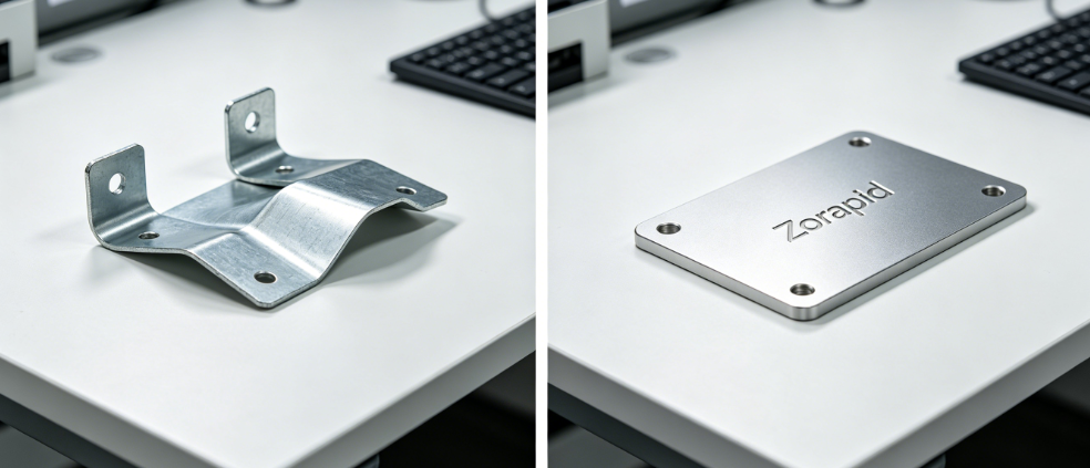
Zorapid Real Bracket Case Study
Project Info
Automation equipment mounting bracket | Material: 2.5mm 304 stainless steel | 4 folded flanges + 6 mounting holes
Original Drawing Problem
The engineer set ±0.1mm tolerance on every linear dimension, plus ±0.2mm hole position across the whole part.
- Production issue: 28% scrap rate due to stainless steel springback
- Lead time extended 3 days for 100pcs
- Quoted cost was 32% higher due to full-part precision inspection
Our Tolerance Revision (No change to assembly fit)
- Keep hole position tolerance at ±0.12mm (critical assembly feature)
- Relax non-critical flange length to ISO 2768-m ±0.3mm
- Adjust bend angle tolerance from ±0.5° up to ±1.0° with springback CNC compensation
- Keep flatness on the bottom mounting face at 0.2mm
Final Result
Scrap rate dropped below 1.1%. Production speed increased, total part cost reduced by 27%, while all bolt holes maintained perfect alignment during on-site assembly.
We finished DFM tolerance revision and updated drawing notes free of charge before starting cutting.
Ready-to-Use Tolerance Note Template
Standard Bracket Drawing Note (ISO 2768-m)
- All untoleranced linear dimensions comply with ISO 2768-1 medium grade (m).
- Bend angle tolerance: ±1.0°; flange length tolerance ±0.3mm.
- Hole position tolerance: ±0.2mm for general bolt holes; ±0.1mm for locating dowel holes.
- Mating flange flatness: 0.3mm / 100mm length.
- Features within 2.5T of bend lines shall have positional tolerance relaxed by 50%.
Precision Fixture Bracket Note
- Critical mounting dimensions follow ISO 2768 fine grade (f).
- Bend angle controlled within ±0.5° with coining compensation.
- Hole true position GD&T: Ø0.1mm at MMC.
- Mounting surface flatness limited to 0.15mm maximum.
How Zorapid Guarantees Tolerance Consistency On Custom Brackets
With more than 20 years in sheet metal fabrication, we deliver consistent bracket accuracy for aerospace, automation, medical and new energy clients across EU and North America.
Our tolerance control system includes:
- Free DFM tolerance audit We review your bracket 3D file, flag unrealistic tight tolerances, adjust bend feature layout and send revised drawing notes within 24 hours — no extra fees.
- Springback CNC compensation Our press brakes run pre-programmed material offset for aluminum, stainless and carbon steel to keep bend variation locked inside your tolerance window.
- First Article Inspection (FAI + CMM Report) We measure hole positions, bend angles and flatness on a coordinate measuring machine before mass production, and share full inspection reports.
- Separate tolerance zoning We split the bracket into critical assembly zones and non-critical blank zones, balancing precision and manufacturing cost intelligently.
We avoid the trial-and-error scrap that comes from poorly defined tolerances.
Conclusion
Most bracket assembly issues are not caused by bad machine work — they start with sloppy, over-tight or missing tolerance rules on your engineering drawing.
Stick to three core principles:
- Use ISO 2768-m as your default baseline for all standard sheet metal brackets.
- Reserve tight fine-grade tolerances only for mounting holes and mating flange surfaces; relax all non-critical features to control cost.
- Always account for bend stack-up, material springback, and hole-to-bend clearance when setting positional limits.
Clear, process-matched tolerances keep your brackets fitting perfectly every run, cut scrap rates, and prevent expensive post-production rework.
Send your bracket DXF or STEP files to Zorapid today. Our sheet metal engineers will complete a full tolerance review and send optimized drawing specifications in one working day.
FAQ
Can I use ±0.05mm tolerance on a folded stainless steel bracket?
You can hold this only on flat laser-cut profiles. After multiple bends, material springback makes ±0.05mm on overall length unrealistic unless you apply coining tooling, which raises cost significantly. We recommend ±0.1~0.15mm as the practical precision limit for bent brackets.
What happens if I do not write any tolerance on the bracket drawing?
The supplier will use loose commercial shop tolerances. Hole positions and bent flanges will vary widely, leading to misaligned assemblies. Always add the ISO 2768 clause on every sheet metal drawing.
How much cost will over-specifying tolerances add?
Applying fine-grade tolerance to the entire bracket usually increases total cost by 20%~45% due to slower cutting and full-part CMM inspection. Zoned tolerances keep cost low while protecting assembly accuracy.
Do thin aluminum brackets need stricter flatness tolerance?
No — thin sheet warps from laser heat. You need to slightly relax flatness limits instead of tightening them, or add fixture support during cooling after cutting.


