Published by:Zorapid.Ltd
Let’s talk about the biggest hidden cost in CNC manufacturing: default tight tolerances on every single dimension.
Most designers copy-paste ±0.01 mm across the whole print just to “play it safe.” No one stops to ask: does this outer non-mating surface really need micron-level precision?
We see this mistake every single day at Zorapid’s 3000㎡ precision machining center. Over-specification slows down spindle speed, burns through cutting tools, requires full CMM inspection, and pushes total part cost up 2x, 3x, even 5x for no functional gain.
You don’t need to sacrifice fit, assembly quality or part lifespan. You only need smarter tolerance selection.
In this post, we break down actionable, shop-tested rules. You will cut unnecessary CNC cost, shorten lead time, and keep your engineering performance fully intact.
Why Over-Tight Tolerances Blow Up Your CNC Budget
Tighter tolerances don’t just add a small markup. They trigger a whole chain of extra work inside the machine shop.
When you tighten a dimension below standard CNC capability, the manufacturer must:
- Slow spindle feed and cutting depth to avoid thermal deformation
- Stop production repeatedly to re-calibrate tool offsets
- Use high-precision solid carbide cutters instead of standard tooling
- Run temperature-controlled 5-axis cells instead of regular milling machines
- Inspect every piece on a CMM machine instead of basic calipers
- Scrap far more parts when tiny size drift goes out of spec
The worst part? 60% of these strict tolerance rules apply to cosmetic, non-locating, non-mating surfaces that never touch another component. You pay premium pricing for features that never affect assembly or function.
Industry data confirms it: 40% of all CNC part overspending comes purely from poorly written tolerance notes on engineering drawings.
The Non-Linear Cost Curve: Tolerance vs CNC Pricing
Cost does not rise evenly as you narrow your tolerance window. The price jumps sharply once you cross standard machine limits.
Here is our shop cost benchmark at Zorapid (Aluminum 6061-T6, 3-axis milling, baseline = ±0.1 mm standard tolerance):
| Tolerance Range | Extra Cost Multiplier | Required Equipment |
|---|---|---|
| ±0.08 ~ ±0.12 mm | 1.0x (baseline) | Standard 3-axis CNC, caliper check |
| ±0.04 ~ ±0.06 mm | 1.4 ~ 1.8x | Precision milling, micrometer inspection |
| ±0.01 ~ ±0.02 mm | 2.8 ~ 4.0x | 5-axis + frequent tool reset, partial CMM |
| ≤ ±0.005 mm | 6 ~ 12x | Climate-controlled cell, grinding + 100% CMM testing |
Key takeaway:
Moving from ±0.1 mm down to ±0.05 mm adds moderate cost. But tightening further to ±0.01 mm more than triples your total expense.
For most commercial, automotive and low-volume aerospace parts, ±0.05 mm hits the sweet spot: solid precision without exponential price hikes. Reserve sub-0.01mm tolerance only for bearing bores, press-fit holes and sealing faces.
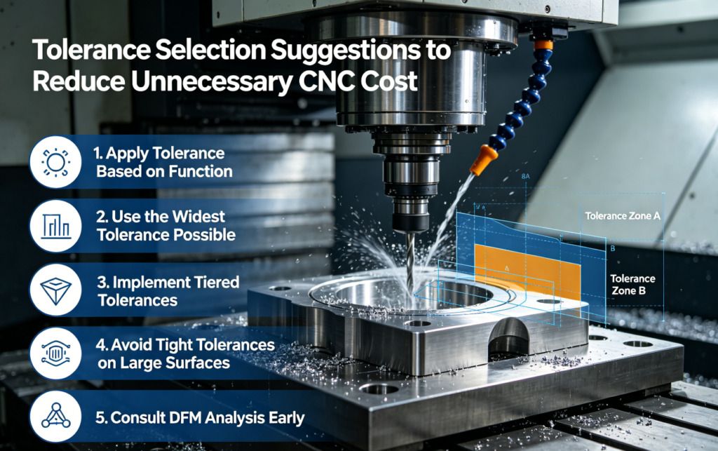
Our Go-To 3-Tier Tolerance Framework (Zorapid DFM Standard)
Stop putting identical tight tolerances on every line item. We teach all our clients to split dimensions into three clear tiers on the drawing. No guesswork for the machinist, no extra cost for your project.
A: Critical Mating Features (Only Here You Use Tight Tolerances)
- Bearing holes, shaft fits, sealing surfaces, alignment dowel holes
- Recommended tolerance: ±0.01 mm ~ ±0.02 mm
- Apply GD&T (position, concentricity) only on these limited features
B: Semi-Locating Assembly Surfaces
- Mounting slots, clearance holes, mating flanges with loose fit
- Recommended tolerance: ±0.05 mm ~ ±0.08 mm
- No complex geometric controls unless assembly demands it
C: Non-Critical Structural & Cosmetic Surfaces
- Outer housing walls, unused flat faces, bracket bodies, decorative profiles
- Use your drawing’s default block tolerance: ±0.1 mm or looser
- No extra inspection required at all
Simple rule to remember:
Tighten Tier A only. Relax Tier B and C fully to machine-shop standard tolerance.
We run this tier check for free during every Zorapid DFM review. In most prints, only 5%~10% of dimensions fall into Tier A. The other 90% can safely run on loose standard limits.
GD&T Traps That Create Hidden CNC Expense
Many engineers add GD&T symbols out of habit, not functional need. Every extra geometric requirement adds setup time and inspection cost.
These GD&T controls drive up cost the fastest:
- Position tolerance with tight boundary on multiple hole patterns
- Flatness over large thin-walled plates
- Concentricity and runout on long turned shafts
- Tight parallelism across multiple disconnected surfaces
Quick Fix:
- Limit position GD&T strictly to hole groups used for precise alignment
- Replace strict flatness requirements with general profile tolerance on non-sealing plates
- Reduce the number of datum references. Match datums directly to how the part gets clamped in fixtures.
When you cut redundant GD&T work, you often eliminate full CMM batch testing entirely, cutting QC labor cost by 35% or higher.
Material Difference: Alloys Shift Your Tolerance Cost Threshold
Your material grade changes how expensive tight tolerances become. Harder alloys need far slower cutting and more frequent tool changes.
Aluminum 6061-T6 / 7075-T6
Holds size well. You can run ±0.02 mm on standard 5-axis machines without huge cost spikes.
Stainless Steel 316L, 17-4PH & Titanium Ti-6Al-4V
Tool wear spikes rapidly. Holding ±0.01 mm adds 60%+ extra cycle time due to thermal expansion. Only lock tight tolerances on truly critical bores.
High-Temp Alloys IN718, H13 Hardened Steel
Thermal drift is severe. Sub-0.01mm tolerance requires temperature-stabilized workshops, which multiplies cost drastically. Loosen every non-mating dimension wherever possible.
Plastics (PEEK, POM, GF-PA66)
Warpage is the main issue. Over-tight tolerances on thin walls lead to high scrap rates. Leave structural plastic features at ±0.1 mm unless sealed fit is required.
Zorapid Real-World Case Study
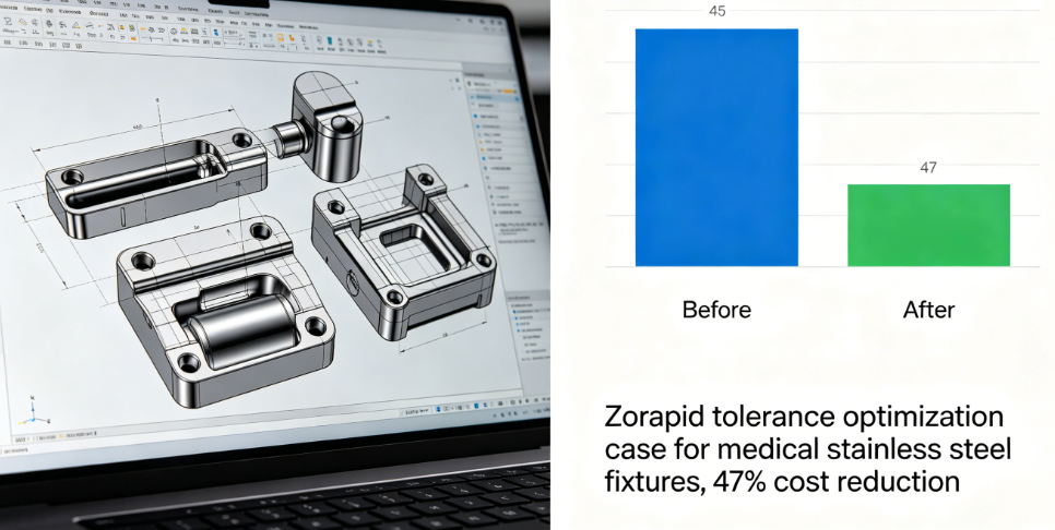
A US medical device client sent us a stainless steel fixture drawing with ±0.01 mm tolerance on every dimension, plus full position GD&T on all 12 holes.
Our DFM team ran a tolerance map:
- Only 2 bore holes needed tight ±0.01 mm for shaft assembly (Tier A)
- 6 mounting holes worked perfectly with ±0.06 mm (Tier B)
- The remaining outer profiles could shift to default ±0.1 mm with zero impact on fixture stability (Tier C)
We also stripped redundant flatness GD&T on the outer plate surface.
Final Result:
- Total CNC machining cost reduced by 47%
- Machining cycle time shortened by 32%
- CMM inspection time cut by 60%
- Part assembly fit and long-term dimensional stability stayed 100% unchanged
The client kept full engineering performance while slashing per-unit cost for small-batch production. This is the exact win we deliver with every tolerance optimization at Zorapid.
Step-by-Step Pre-Quote Tolerance Checklist
Run this quick check before you send drawings to any CNC machine shop:
- Highlight all mating, sealing and bearing features. Mark these Tier A only.
- Set all non-assembly dimensions to your title block’s default loose tolerance.
- Delete every GD&T symbol that does not directly affect part fit and function.
- Check material grade: loosen tight limits further on titanium, stainless steel and high-temperature alloys.
- Send your print to Zorapid for a free DFM tolerance review before requesting formal quotes.
Five minutes of drawing cleanup often knocks 30% off your final invoice.
FAQ
What is the standard default CNC tolerance I should use for non-critical features?
Stick with ±0.1 mm (±0.004 inch) for all non-mating surfaces. This matches the baseline capability of most 3-axis and 5-axis CNC mills with no extra production cost.
Will relaxing tolerances create fit issues during assembly?
No, if you follow the 3-tier rule. Only loosen dimensions that never touch other parts. All mating interfaces stay locked at precision tolerance. Our clients never report assembly problems after tolerance optimization.
Can I lower CNC lead time by adjusting tolerance settings?
Absolutely. Ultra-tight micron tolerances require scheduled precision cell time, which pushes lead times out 7~14 days. Relaxing non-critical tolerances lets us run parts on regular production lines and ship faster.
Does Zorapid offer free tolerance & DFM analysis for CNC drawings?
Yes. We provide no-charge DFM reviews for all incoming CNC projects, including tolerance rationalization, GD&T cleanup and thin-wall warpage checks for aerospace, medical, semiconductor and automotive components.
Closing
Tolerance selection is not just engineering detail. It is your biggest lever to control CNC part cost.
Stop paying premium prices for unnecessary micron precision on cosmetic surfaces. Separate critical mating features from basic structural geometry, apply our 3-tier framework, and cut 30%~50% of unnecessary manufacturing expense without sacrificing part quality.
If you have a CNC drawing waiting for quotation, send your files to Zorapid right now. Our engineering team will sort your tolerances, strip redundant GD&T, and deliver the most cost-effective machining plan for your prototype or low-volume production run.
Free DFM & Tolerance Review | Send your CAD files | Zorapid Precision CNC Machining | ISO Certified 5-Axis & Hybrid Manufacturing