
Published:Zorapid.Ltd
5-axis CNC machining is advanced subtractive computer numerical control manufacturing. It enables cutting tools or workpieces to move along 3 linear axes (X/Y/Z) plus 2 independent rotary axes (A/B/C) simultaneously. Unlike 3-axis CNC limited to vertical fixed spindle cutting, 5-axis machines access nearly all workpiece angles, machining complex curved, multi-angle components in one clamping setup. It is widely applied in aerospace, medical implants, automotive molds, turbine parts, and precision semiconductor hardware.
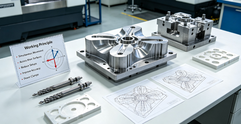
Basic Definition & Axis Naming Rules
All CNC machine motion falls into linear axes and rotary axes.
- Linear axes: X (left-right), Y (front-back), Z (up-down). These three axes exist on all CNC milling machines.
- Rotary axes: A, B, C. Named based on their rotation centerline:
- A axis: Rotation around the X-axis
- B axis: Rotation around the Y-axis
- C axis: Rotation around the Z-axis
A standard 5-axis machine integrates X+Y+Z linear axes + 2 rotary axes. Different machine structures carry different rotary combinations (A/C, B/C are most common for industrial milling). The spindle or worktable can tilt and spin synchronously.
Two Major 5-Axis Operating Modes (Critical for Designers & Buyers)
Not all 5-axis machines work the same way. They split into positional 3+2 5-axis and simultaneous continuous 5-axis, with totally different usage and costs.
3+2 Indexed 5-Axis (Positional 5-Axis)
Working principle The machine rotates and locks the spindle/worktable to a fixed tilt angle first. Once angles are locked, the tool runs regular 3-axis milling motion. Rotation stays stationary during actual cutting.
- Every new tilt angle requires one index lock action.
- CAM programming is highly similar to regular 3-axis programming, with low technical barriers.
Suitable features: fixed-angle inclined holes, tilted flat planes, angled slots, tilted rectangular pockets.
Continuous Simultaneous 5-Axis
Working principle All five axes move synchronously at all times during cutting. The tool tip continuously adjusts its angle to stay perpendicular to curved surfaces. The cutting path follows organic freeform geometry dynamically.
- CAM simulation and programming are complex, needing full 5-axis toolpath verification to avoid collision.
Suitable features: smooth organic curves, turbine blades, medical implant contours, sculpted molds, uninterrupted curved blending surfaces.
Common 5-axis Machine Structures
- Table-Tilting 5-axis: Worktable rotates/tilts; spindle remains fixed. Good for medium/small workpieces, high rigidity.
- Head-Tilting 5-axis: Spindle head tilts; table only rotates. Fits long oversized parts with limited table travel.
- Hybrid Head-Table 5-axis: Both spindle and table have rotary movement, highest flexibility for varied part sizes.
mplete Working Principle of 5-Axis Machining
- CAD & CAM Preparation Designers complete 3D CAD models. Programmers build 5-axis toolpaths in CAM software, adding collision checking for spindle, fixture, workpiece and machine limits. The program outputs coordinates for all 5 moving axes.
- Workpiece Single-Setup Clamping Operators fix the blank on fixtures once. No need to remove and re-clamp the part multiple times. The machine’s rotary axes reach nearly all outer surfaces by tilting the part or spindle.
- Multi-Angle Cutting Execution
- For 3+2: Axis tilts lock at target angles; X/Y/Z complete milling, drilling and tapping. The machine indexes to other angles for remaining features.
- For simultaneous 5-axis: Five axes coordinate movement continuously. The cutting angle keeps consistent against curved surfaces to maintain uniform contact.
- One-Time Complete Machining After all angles and surfaces are machined, the part is unloaded. All dimensional tolerances reference the same original clamping datum. No cumulative positioning errors from repeated re-fixturing.
Core underlying logic: Rotary motion eliminates the limitation of fixed spindle orientation. Tools access angled and curved surfaces without repositioning the workpiece.
7 Core Advantages of 5-Axis CNC Machining
Exceptionally Higher Geometric Precision & Stable GD&T Tolerance
3-axis multi-clamping shifts part datums every time you reposition the blank, accumulating positional deviation. 5-axis completes most features in one clamping. All holes, planes and profiles share the identical datum, drastically improving position tolerance, perpendicularity and concentricity. It meets strict GD&T requirements for aerospace and medical components.
Better Surface Finish with Reduced Tool Vibration
When machining deep angled cavities with 3-axis mills, machinists must use long, slender tools prone to chatter and vibration. 5-axis tilts the spindle to use short, rigid cutting tools. Shorter tools have minimal deflection and vibration, delivering smoother surface roughness (lower Ra value) and fewer chatter lines. Surface consistency across curved surfaces improves significantly.
Wider Design Freedom for Complex Geometry
Features impossible or uneconomical for 3-axis are machinable on 5-axis:
- Deep angled hole arrays
- Continuous freeform curved surfaces
- Mild undercut structures
- Complex twisted contours (blades, impellers)
Engineers are no longer forced to simplify functional geometry to fit 3-axis machining limits. Lightweight complex structural designs become feasible.
Shorter Total Production Lead Time
3-axis complex parts need multiple setups, manual re-clamping, repeated alignment and extra inspection steps. These manual operations waste hours or days. 5-axis cuts all manual fixture adjustments. Total machining and handling time drops sharply, especially for low-volume prototypes and customized precision parts. Faster turnaround accelerates product iteration.
Lower Total Scrap Rate
Every manual re-clamping introduces human error. Misalignment causes out-of-tolerance dimensions and scrapped parts. Single-setup 5-axis removes most human positioning variables, lowering reject rates and reducing material waste cost.
Uniform Surface Texture on Curved Parts
On 3-axis curved surface milling, the tool hits different surface angles randomly, leaving uneven tool marks and inconsistent roughness. Simultaneous 5-axis keeps the tool contact angle consistent across the entire curve. Stepover stays even, creating uniform matte or glossy finish without patchy texture. Less post-polishing work is needed.
Simplified Fixture Design
3-axis needs multiple custom fixtures for different machining sides. 5-axis often uses simple standard vises or zero-point fixtures. Fewer custom fixtures cut fixture manufacturing cost and shorten pre-production preparation cycles.
Typical Industries & Parts That Rely on 5-Axis CNC
- Aerospace & Aviation Turbine blades, engine housings, aircraft structural brackets, landing gear components, complex titanium structural parts. Strict tolerance + curved aerodynamic surfaces make 5-axis mandatory.
- Medical Devices Titanium orthopedic implants, spinal plates, surgical instrument housings. Biocompatible alloys demand high precision; complex ergonomic curves require simultaneous 5-axis cutting.
- Mold & Die Manufacturing Injection mold cavities, blow molds, die-cast molds with deep curved contours. 5-axis delivers smooth mold surfaces and reduces hand polishing work.
- Automotive Racing High-performance engine manifolds, turbo parts, custom racing cylinder heads. Complex curved flow paths rely on multi-angle 5-axis machining.
- Semiconductor & Automation Equipment Precision vacuum chambers, semiconductor jigs, multi-angle fluid manifolds. Tight dimensional accuracy and clean smooth surfaces match 5-axis strengths.
Clear Difference: 3+2 vs Continuous 5-axis (Cost & Application Reference Table)
| Item | 3+2 Indexed 5-Axis | Continuous Simultaneous 5-Axis |
|---|---|---|
| Axis motion | Locked rotary angles, only X/Y/Z cut | All axes move synchronously during cutting |
| Programming difficulty | Low; similar to 3-axis CAM | High; requires full collision simulation |
| Machining hourly cost | Moderate (20%–40% higher than 3-axis) | Premium (50%–100% higher than 3-axis) |
| Best geometry | Fixed tilted holes, angled planes, angled pockets | Smooth freeform curves, twisted blades, organic surfaces |
| Surface uniformity | Good for flat tilted surfaces | Perfect for continuous curved surfaces |
| Most suitable | Prototypes, general precision parts, bulk angled features | High-end curved aerospace/medical parts |
Frequently Asked Questions
Is 5-axis always better and replaces 3-axis CNC?
No. Simple flat prismatic blocks, regular straight holes and standard simple parts gain zero benefit from 5-axis. 3-axis costs less and runs faster for basic geometry. 5-axis is targeted at complex multi-angle/curved workpieces rather than all machined parts.
Can 5-axis machine all sides of any part in one clamping?
Most outer surfaces are machinable in one setup. Fully enclosed internal sealed cavities still need two-sided clamping. Design open geometry whenever possible to achieve full single-setup machining.
Why do many factories choose 3+2 5-axis instead of continuous 5-axis?
3+2 has lower programming cost, cheaper machine time and stable precision for most angled industrial parts. Most consumer equipment, automation fixtures only need fixed tilt angles; simultaneous 5-axis would bring unnecessary extra cost.
Does 5-axis eliminate all clamping errors entirely?
It removes errors caused by multiple re-clamping. Minor errors still exist from machine precision, tool wear and original fixture alignment, but tolerance stability improves drastically compared with repeated 3-axis setups.
Can 4-axis replace 5-axis for round rotary parts?
4-axis (X/Y/Z + single rotary C axis) works well for cylindrical shafts and radial holes with only rotational movement. It cannot tilt the spindle to machine non-radial tilted angles, so complex tilted curved parts still require 5-axis.
Final Summary
5-axis CNC machining adds two rotary axes on top of basic X/Y/Z linear travel, split into indexed 3+2 and continuous simultaneous operation modes. Its core value lies in single-setup machining: higher dimensional accuracy, cleaner surface finish enabled by short rigid tools, greater design flexibility, faster lead times and fewer defective parts.
Designers and manufacturers should select reasonably: use low-cost 3+2 5-axis for parts with fixed-angle inclined features, reserve continuous 5-axis exclusively for smooth freeform curved components. Simple flat parts remain most cost-effective on standard 3-axis mills. Matching part geometry with the right 5-axis mode balances precision, lead time and overall manufacturing cost.


