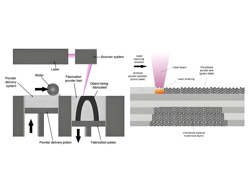
Selective Laser Sintering (SLS) is an additive manufacturing technology that forms parts by layer-by-layer stacking through the interaction between laser and powder materials. It generally adopts a CO₂ laser as the light source and selectively scans each layer according to the layered data input from a computer.
As an additive manufacturing technology with high flexibility and adaptability, SLS breaks through the technical limitations of material deformation forming and subtractive manufacturing. It fabricates parts by adding materials without the need for molds or support structures. Boasting high design freedom, shortened product R&D cycles and low manufacturing costs in producing complex-shaped parts, it enables the rapid fabrication of complex components made of polymers, metals and ceramics.
Principle of Selective Laser Sintering Forming
Before scanning, selective laser sintering preheats the powder to a temperature below its melting point, which reduces thermal deformation and powder sticking during laser scanning, and facilitates bonding between adjacent layers.
Computer software controls laser operation and power regulation, as well as the entire laser printing process, powder preheating, and the movement of the powder spreading roller and powder cylinder.
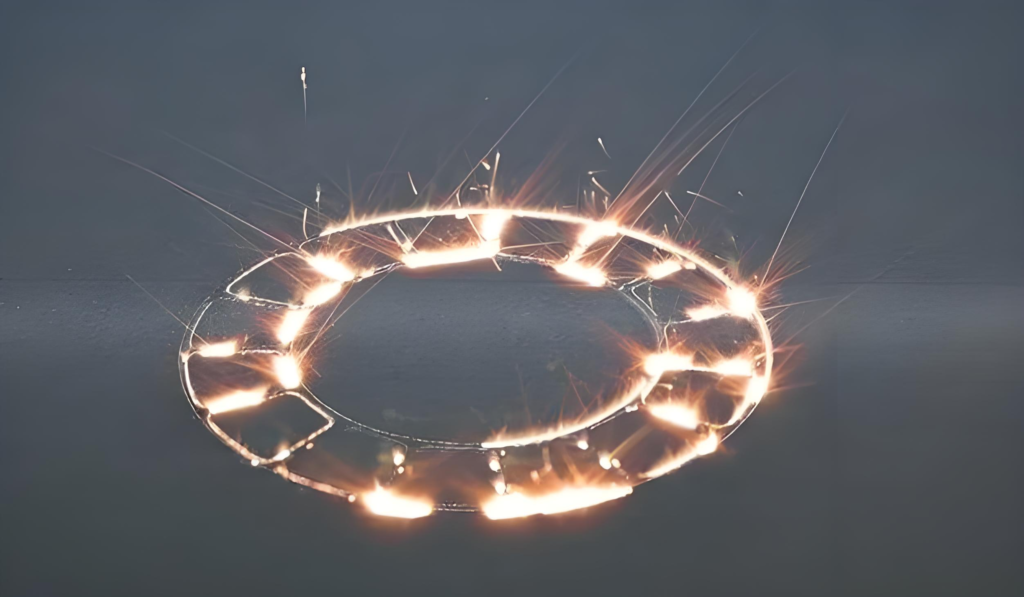
After determining the laser process parameters such as laser power, scanning speed, scanning spacing, and layer thickness, the computer controls the laser to emit a high-precision laser beam. The beam selectively scans the powder bed according to the imported 3D layered model data. The scanned area on the powder layer absorbs laser energy and its temperature rises continuously. When the temperature reaches the softening point or melting point of the powder material, the scanned powder gradually flows. Individual powder particles come into contact with each other, form sintering necks, and bond together to take shape. The unscanned area remains in a loose powder state and acts as natural support for the sintered region.
After the laser completes scanning the designated area
part of the heat transfers to the underlying powder layer through thermal conduction, creating a bonded connection between the scanned layer and the lower powder layer. The remaining heat gradually dissipates via surface convection and radiation, causing the temperature to drop. The powder particles cool and solidify gradually, bonding with one another within the scanned area to form the required contour.
Once the laser beam finishes scanning one sliced layer, the build cylinder descends by one layer thickness, while the corresponding feed cylinder rises by a height proportionate to the layer thickness. The powder spreading roller then translates and rotates toward the build cylinder, pushing excess powder from the feed cylinder above the working plane to evenly cover the surface of the powder bed in the build cylinder.
This covers the previously sintered layer with a fresh powder layer of precise slice thickness. The system then proceeds with sintering the next layer. This process repeats continuously with layer-by-layer stacking until the entire part is fully sintered and formed.
After full cross-section sintering, take the printed part out of the powder bed, clean all unsintered powder from surfaces and complex internal structures, then grind, dry and finish to get the final 3D solid part.
As a rapid manufacturing technology completely different from traditional subtractive manufacturing, SLS offers numerous advantages in part fabrication:
Wide range of material sources
Theoretically, any powder capable of particle bonding via laser sintering can serve as SLS forming material.
Simple manufacturing process
The whole process is fully computer-controlled. Just design the model and prepare raw materials, then SLS can make parts — greatly simplifying production.
High forming accuracy
Part precision relies on laser scanning accuracy and heat-affected zone size, both adjustable via SLS process parameters.
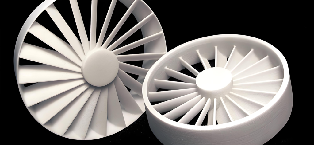
Suitable for manufacturing complex-shaped parts without support structures or molds
Unscanned unsintered powder stays intact after laser scanning and naturally supports overhangs. No mold design needed, enabling free fabrication of highly complex parts.
High material utilization rate
Unused unsintered powder is fully recyclable, boosting material utilization and cutting production costs.
Selective Laser Sintering Process
A wide variety of powder materials are now available for laser sintering technology to fabricate components of corresponding materials. With mature process technology, printed parts generally feature high precision and superior strength.
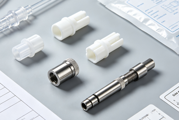
The biggest advantage of SLS lies in its capability to directly print finished metal parts. The fabricated components can fully meet functional testing requirements. Laser sintering supports both direct and indirect sintering of metal parts, and the final parts deliver far higher material strength than those made by other 3D printing technologies.
From the SLS working principle above, its process steps can be summarized below.
The print chamber stays slightly below the powder’s melting point throughout printing. Powder is evenly spread and leveled over the finished part layer. A high-power CO₂ laser scans the part’s cross-section on the new powder bed. Intense laser heat sinters the powder and bonds it to the layer below. After one layer sinters, the system lays fresh powder and repeats for the next layer.
Laser Sintering Technology
Although laser sintering technology boasts remarkable advantages, it also has inherent limitations. Firstly, powder sintering results in rough surface finish, which requires subsequent grinding and post-processing. Secondly, it relies on high-power lasers, bringing high equipment and maintenance costs, as well as the need for supporting protective and control components. The overall equipment features high technical complexity and manufacturing difficulty, making it unaffordable for ordinary users and hard to achieve large-scale popularization.
Process Parameters of Selective Laser Sintering
High-quality SLS printed parts require sufficient dimensional accuracy and mechanical strength.Insufficient accuracy of formed parts will make the final products fail to meet application requirements; if the strength is too low, the parts cannot maintain complex geometric shapes, nor withstand post-processing operations after printing, resulting in part damage and substandard strength that render the parts unusable.
Sufficient softening and bonding of powder particles are essential to improve the strength of SLS parts, which requires adequate heat input in the laser sintering zone to melt the powder particles. However, excessively high laser energy density will expand the heat-affected zone caused by thermal conduction, leading to large dimensional errors and poor forming accuracy.Therefore, it is necessary to comprehensively consider the influence of laser energy density on both strength and accuracy, so as to formulate reasonable process parameters.
Laser Power
The output of laser energy is mainly determined by laser power. When laser acts on powder material, the generated heat has three dissipation paths:
Absorption by powder in the selected sintering region;
Transfer to the surrounding area through thermal conduction;
Dissipation into the air via convection, radiation and reflection.
The laser beam acts as a moving heat source, and its interaction time with powder generally ranges from several milliseconds to tens of milliseconds. Therefore, the heating and cooling rate of the powder is extremely fast.
During heating, the thermophysical properties of powder material such as laser absorptivity, reflectivity and thermal conductivity change with rising temperature. Meanwhile, the temperature at every point inside the powder bed varies constantly. This is an extremely complex unsteady heat transfer process.
Scanning Speed
During the laser sintering forming process of powder materials, as the laser scans within the working plane, powder particles melt under laser irradiation, flow and bond with each other. The laser scans point by point to form lines, then scans line by line to form planes, and finally accumulates layer by layer to form a solid part.
When the scanning speed decreases, the laser energy density increases, and the energy absorbed by the material around the scanning spot rises accordingly. This expands the width and depth of the molten region, which helps improve the mechanical strength of the formed part.
The width and depth of the molten region have a significant influence on scanning spacing and layer thickness. Therefore, the scanning speed must be matched reasonably with these two parameters.
Reducing the scanning speed will lower manufacturing efficiency. Meanwhile, when the laser scans the part boundary, the expanded molten region enlarges the heat-affected zone, resulting in reduced dimensional accuracy of the printed part.
Scanning Spacing
Scan spacing is the gap between adjacent laser scan lines. Only powder inside scan lines sinters, while the scanned temperature field minimally affects surrounding powder.
Scan spacing is typically set slightly smaller than laser spot diameter. This creates slight overlap between adjacent scan lines, eliminating layer bonding boundaries and ensuring full-layer fusion. It also minimizes thermal impact on surrounding powder and secures the sintered part’s dimensional accuracy.
Layer Thickness
Layer thickness refers to the powder spreading depth, namely the height by which the build cylinder descends for each layer.The distribution of laser energy density gradually decreases along the thickness direction, which limits the feasible sintering layer thickness. Excessively large layer thickness will result in weak interlayer bonding, possibly causing delamination of the green part and reduced mechanical strength in the height direction. By contrast, overly small layer thickness may cause re‑sintering of already sintered powder and degrade the forming quality of the part.
During powder laying, the spreading roller exerts downward pressure on the powder, which helps increase the powder bulk density. Accordingly, the smaller the layer thickness, the higher the density of the sintered part. Meanwhile, the roller also produces a horizontal force, which may cause slight displacement between layers and reduce dimensional accuracy. Especially for parts with curved surfaces, laser sintering tends to form a stepped profile instead of a smooth transition, lowering both the surface finish and geometric accuracy of the green part.
For curved components, the machining error generated during laser sintering is related to both the slope of the curved surface and the layer thickness. As layer thickness increases, the staircase effect becomes more prominent, enlarging deviations in volume, shape and dimension between the actual sintered part and the original design. Therefore, when fabricating curved green parts, it is advisable to appropriately reduce the layer thickness and carefully select the building orientation to achieve higher forming accuracy.
Spot Diameter
When the laser beam irradiates the powder surface, it forms a light spot with a certain size. During laser sintering of powder materials, there is a deviation between the contour of the formed part and the scanning trajectory of the spot center, which leads to dimensional enlargement of the part’s outer profile.
The laser spot also rounds off sharp corners of the formed part and impairs its geometric accuracy. To a certain extent, the influence of spot size on part accuracy outweighs the effect of powder particle size.
The laser spot diameter also has a significant impact on forming efficiency. At the same scanning speed, increasing the spot diameter improves the uniformity of laser energy density distribution and allows a larger scanning spacing, thereby boosting production efficiency.
Adopting a small spot diameter helps enhance interlayer bonding strength and improves the mechanical properties of formed parts.
With variable spot technology, small spots can be used for boundary scanning and large spots for internal scanning. This method not only improves scanning efficiency and reduces thermal deformation, but also produces formed parts with higher mechanical strength.
SLS Selective Laser Sintering Materials
Selective Laser Sintering (SLS) is a powder bed-based additive manufacturing technology. The properties of powder materials exert a great influence on the performance of SLS printed parts, among which the particle size, particle size distribution and particle morphology of powder are the most critical factors.
SLS supports a wide range of forming materials. At present, a variety of SLS materials have been developed both at home and abroad. According to material properties, they can be classified into the following categories: metal-based materials, ceramic-based materials, coated sand, and polymer materials.
Polymer Materials
A prominent advantage of SLS technology is its compatibility with a wide range of materials, including polymers, metals, and ceramics. Compared with metals and ceramics, polymer materials feature lower forming temperature, lower required laser sintering power, and higher dimensional accuracy. For this reason, polymers have become the earliest, most widely used, and most successful SLS forming materials, occupying a vital position in SLS material systems. Their diverse grades and properties, together with various modification technologies, further broaden their application prospects in SLS.
SLS uses polymer powder with average particle size 10–100 μm. The powder must melt, soften or bond with laser energy without serious thermal degradation. Mainstream SLS polymers are thermoplastics and their composites, classified as crystalline or amorphous.
Amorphous Polymers
For amorphous polymers, the movement of macromolecular chain segments becomes active at the glass transition temperature (Tg), causing the powder to start bonding and its fluidity to decrease.
In the SLS process, the preheating temperature of amorphous polymer powder must not exceed Tg. To reduce warpage of sintered parts, the preheating temperature is usually set slightly below Tg. After the material absorbs laser energy, its temperature rises above Tg and sintering occurs.
Amorphous polymers exhibit high viscosity at Tg, and the sintering rate is inversely proportional to material viscosity. This results in a low sintering rate for amorphous polymers. The sintered parts feature low density and mechanical strength with a porous structure, yet maintain relatively high dimensional accuracy.
Increasing laser energy density can improve the density of sintered parts. However, excessively high laser energy density often triggers severe thermal decomposition of the polymer, which instead reduces part density. It also intensifies secondary sintering and degrades dimensional accuracy.
Amorphous polymers are generally used to fabricate parts with low strength requirements but high dimensional accuracy.
Common amorphous polymers applied in SLS include: Polycarbonate (PC), Polystyrene (PS), High Impact Polystyrene (HIPS), and Poly(methyl methacrylate) (PMMA).
Crystalline Polymers
The sintering temperature of crystalline polymers is above the melting temperature (Tm). Above Tm, crystalline polymers possess extremely low melt viscosity, leading to a high sintering rate and excellent densification of sintered parts, generally over 95%. When the bulk material has high intrinsic strength, crystalline polymer sintered parts deliver superior mechanical strength.
Crystalline polymers undergo substantial shrinkage during melting and crystallization, accompanied by significant volumetric shrinkage during sintering. This makes crystalline polymers prone to warpage and deformation in the sintering process, resulting in poor dimensional accuracy of finished parts.
Nylon is the most widely used crystalline polymer for SLS. Other crystalline polymers applied in SLS include polypropylene, high-density polyethylene, and PEEK (Polyether Ether Ketone).
Industrial thermoplastics typically come in pellet form, which must be ground into fine powder for SLS use.
Polymer materials feature viscoelasticity. When pulverized at room temperature, heat generated during grinding increases their viscoelasticity, making pulverization difficult. Meanwhile, crushed particles tend to re-bond, lowering grinding efficiency and even causing melting and wire drawing. Conventional pulverization methods cannot produce powder that meets SLS process requirements.
Cryogenic pulverization is the standard method for making micron‑level polymer powder. It leverages polymer low‑temperature brittleness to produce qualified powder. Common polymers including polystyrene, polycarbonate, PE, PP, polymethacrylates, nylon, ABS and polyester can all be powdered by this method.
Zorapid’s 3D printing services mainly cover materials including PA11, PA12, glass-filled PA12, TPU and PP.
Coated Sand Materials
SLS-grade powder is made by coating zircon and quartz sand with phenolic and other thermosetting resins.
During the laser sintering process, laser heating softens and cures the phenolic resin, bonding the coated sand particles to complete forming.
Laser heating is extremely brief, leaving phenolic resin under-cured and sintered parts with low initial strength.
Therefore, the sintered parts require post-heat treatment. Post-curing enables the parts to serve as foundry sand molds and cores for metal casting.
Metal-Based Powder Materials
In the indirect SLS method for forming metal parts, metal powder is uniformly blended with polymer powder serving as the binder. The powder material absorbs laser energy, and the resulting temperature rise softens or even melts the polymer binder into a viscous flow state, bonding the metal powder particles together to form an initial green metal part. Subsequent processes such as debinding, high-temperature sintering, metal infiltration, or resin impregnation are then adopted to obtain the final metal components.
Another approach adopts low-melting-point metal powders such as copper (Cu) and tin (Sn) as binders to fabricate composite metal parts. This type of metal binder remains inside the green part after forming. Low-melting-point metal binders possess good inherent strength, enabling the green parts to achieve high densification and mechanical properties. High-performance metal parts can be obtained without post-treatment procedures like debinding and high-temperature sintering.
With the development of SLM technology, research on fabricating metal parts via SLS is gradually declining.
Application of Selective Laser Sintering Forming Technology
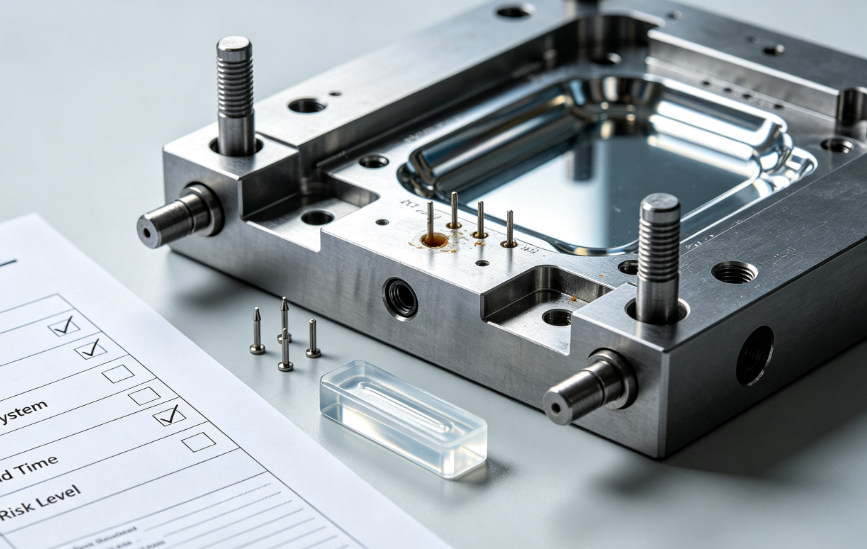
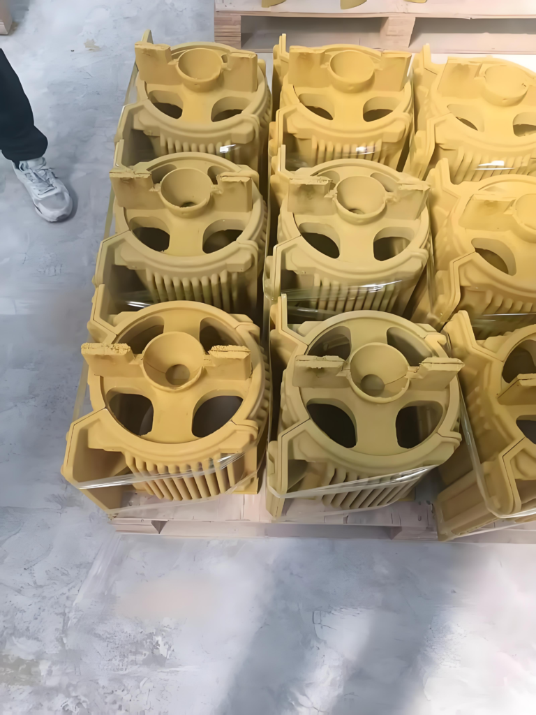
Forming of Foundry Sand Cores, Molds and Investment Patterns
Large, complex and precision investment patterns and sand molds can be fabricated within hours or even days by using large-format Selective Laser Sintering (SLS) equipment with investment casting and sand mold materials.
During forming, under a preset preheating temperature, a layer of powder material is first spread on the building platform by a powder laying roller. Under computer control, the laser beam scans the powder within the solid section contour of the investment pattern and sand mold according to sectional profile data. The powder temperature rises to the melting point, causing melting at the boundaries of powder particles and bonding them together.
The unsintered powder remains loose and acts as support for the fabricated part and the subsequent powder layer. Once one layer is completed, the building platform descends by one layer thickness, followed by powder spreading and sintering of the next layer. This cycle repeats until a three‑dimensional investment pattern or sand mold is finally formed.
The rapidly formed investment patterns and sand molds are applied in investment casting and sand casting to manufacture key components for high-demand fields including aerospace, military industry, shipbuilding, automotive and machine tools in China.
This technology simplifies the process flow, shortens production cycles and reduces manufacturing costs, enabling the casting process to cut both cost and lead time by half, and upgrading the overall level of traditional casting technology.
The fabrication of coated sand cores by SLS technology possesses broad application prospects in the foundry industry.
Biomanufacturing
The SLS forming of biopolymers for the fabrication of customized medical implants and tissue engineering scaffolds is currently one of the research hotspots in the SLS field.
With computer-aided design, SLS technology enables the fabrication of three-dimensional interconnected porous tissue scaffolds and personalized biological implants with controllable structure and mechanical properties. It allows effective regulation of porosity, pore morphology, pore size and external structure, thereby promoting cell adhesion, differentiation and proliferation and improving the biocompatibility of scaffolds.
At present, biopolymers applicable to SLS are mainly synthetic polymers, including poly(L-lactic acid) (PLLA), polycaprolactone (PCL), polyether ether ketone (PEEK), and polyvinyl alcohol (PVA). These materials are often compounded with bioactive ceramics such as hydroxyapatite (HAp) or β-tricalcium phosphate (β-TCP) to achieve favorable bioactivity.
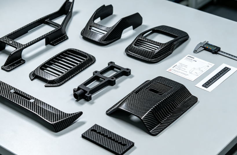
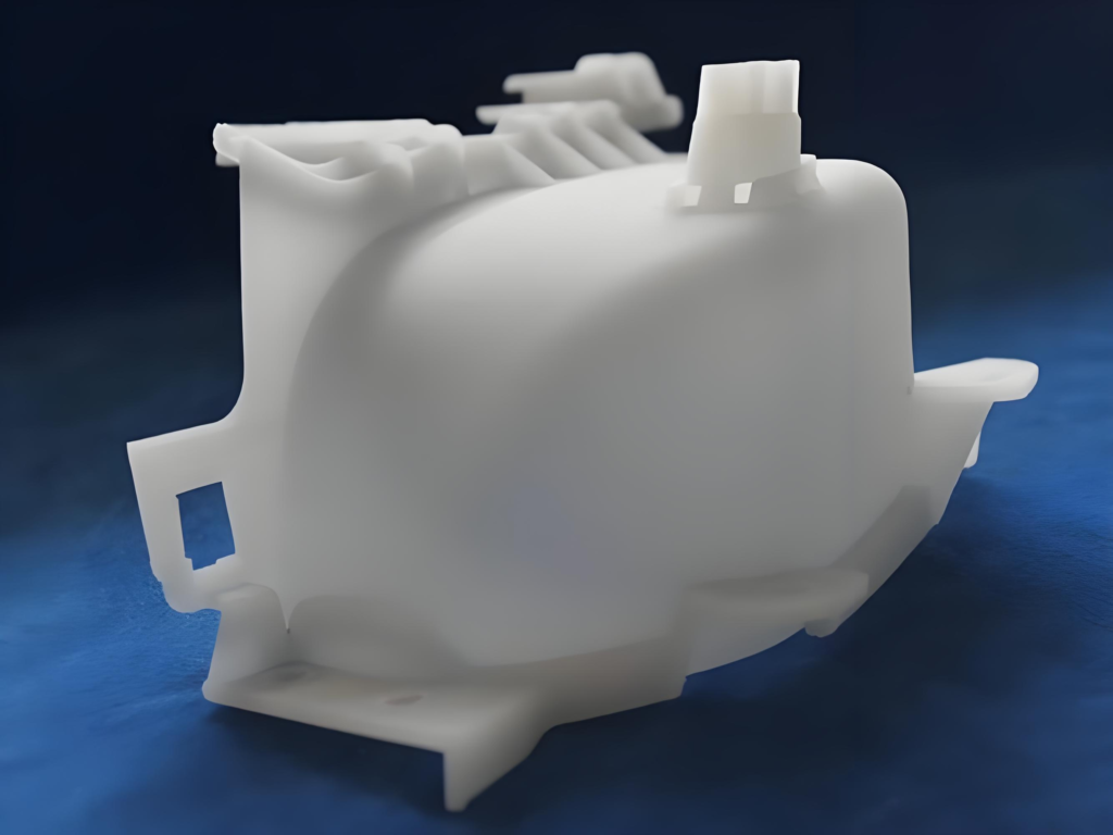
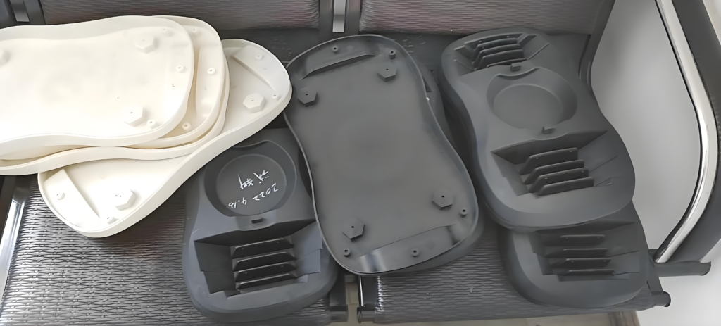
Manufacturing of Polymer Functional Parts
Polymer parts fabricated by SLS exhibit excellent comprehensive performance and can be directly applied as plastic functional components.
The main materials used for SLS forming are thermoplastic polymers and their composite materials. Thermoplastic polymers can be further divided into crystalline and amorphous types. Due to the distinct differences in thermal properties between crystalline and amorphous polymers, there are significant disparities in laser sintering parameter configuration and the final performance of formed parts.
About Us
Zorapid specializes in customized manufacturing services for non-standard parts.Our manufacturing capabilities cover CNC machining, sheet metal processing, aluminum profile fabrication and more.From conceptual design to functional prototypes, and from one-piece rapid prototyping to low-volume production of up to 5,000 units, we leverage our in-house quality factory and partnered manufacturing capacity to help you achieve the fastest product development timeline.
Core Principle
Powder Deposition: A roller spreads a thin powder layer of 0.05–0.1 mm on the build platform.
Laser Sintering: The laser scans following the cross-section of the 3D model. Powder is heated close to its melting point (approximately 180℃ for PA12), and particles fuse together.
Layer-by-Layer Stacking: The platform descends by one layer height, and the process of powder deposition and laser sintering repeats until the part is fully completed.
Powder Cleaning: Unsintered powder naturally supports the part. After printing, the part can be easily taken out by pouring out the loose powder.
Key Features
Support-Free Printing: Unsintered powder acts as natural support, enabling the fabrication of hollow structures, internal cavities and overhanging geometries.
Industrial-Grade Strength: Parts feature high density and good toughness, with performance close to injection-molded components.
High Material Utilization: Unsintered powder is recyclable, with a recycling rate of about 80–90%.
Efficient Batch Production: Multiple parts can be nested within one powder bed and printed simultaneously.
FAQ
Is post-processing complicated?
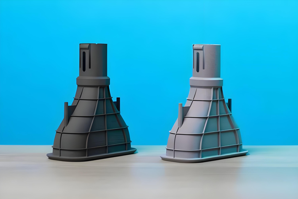
Basic post-processing:Powder cleaning (compressed air / brush) → remove residual loose powder.
Advanced post-processing:
- Sandblasting: Achieve a finer surface finish;
- Dyeing / Spraying: Add color and improve weather resistance;
- Resin impregnation: Seal surface pores and enhance mechanical strength.
Can it print metal?
Strictly speaking, no. SLS is mainly designed for polymer powder materials.
For metal parts, choose SLM/DMLS: Selective Laser Melting adopts higher-power lasers to fully melt metal powders such as titanium alloy and aluminum alloy, which belongs to the category of metal 3D printing.
What are the commonly used materials?
PA12 (Nylon 12): The most widely used material with balanced strength, toughness and chemical resistance.
PA11: Better flexibility and outstanding impact resistance.
Glass-filled PA6: High strength and heat resistance, ideal for structural parts.
TPU / TPE: Elastomers for flexible components such as seals and insoles.
PS (Polystyrene): Used for lost foam casting (burn-out disposable pattern).