
Published:Zorapid.Ltd
Optical precision parts cover optical lens molds, semiconductor laser cavity housings, aerospace optical sensor brackets, medical endoscope optical frames and precision optical reflector substrates. These components demand far stricter surface quality than regular mechanical hardware. Tiny tool chatter marks, uneven machining lines, micro burrs or inconsistent roughness lead to light scattering, imaging distortion, laser beam refraction failure and scrap.
Traditional 3-axis CNC struggles to deliver uniform surface quality on curved freeform optical surfaces. Repeated re-clamping creates alignment errors, tool vibration and patchy texture. 5-axis CNC changes the game by enabling single-setup multi-angle machining. Still, many manufacturers fail to hit optical-level surface finish even with 5-axis equipment.
This guide breaks down actionable 5-axis optimization tactics for optical-grade surface roughness (Ra 0.02 μm ~ Ra 0.2 μm). We cover axis movement logic, tool selection, cutting parameters, coolant solutions, fixturing, post-process matching, common defects troubleshooting, paired with designated watermark-free HD image references, and wrap up with targeted for optical component manufacturers.
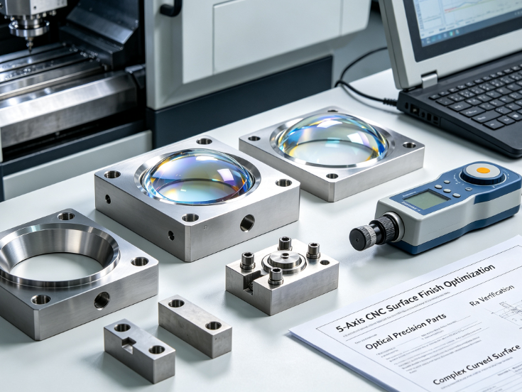
Core Standards of Optical CNC Surface Finish
Optical components classify surface requirements strictly by application, all measured under ISO 4287 profilometry:
| Optical Part Category | Required Ra Range | Key Surface Requirements |
|---|---|---|
| Precision optical lens injection molds | Ra ≤ 0.02 μm (mirror finish) | Zero tool lines, no micro pits, burr-free, uniform texture |
| Semiconductor laser optical chambers | Ra 0.1–0.2 μm | Low particle shedding, consistent smoothness, no embedded chips |
| Aerospace optical reflector substrates | Ra 0.05–0.1 μm | Isotropic surface, directional machining marks eliminated |
| Medical endoscope optical hardware | Ra ≤ 0.2 μm | Smooth, easy cleaning, no micro crevices gathering dust |
Critical rule for optics: Directional linear tool scratches cause anisotropic light reflection. Optical finish needs random, uniform texture rather than regular parallel milling lines. 5-axis flexible spindle orientation is the only reliable way to break directional tool patterns.
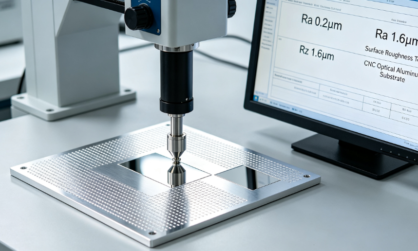
Why 5-Axis Is Irreplaceable for Optical Surface Quality
- Single-setup full-part machining eliminates setup marks All curved optical contours, angled mounting holes and mating surfaces are machined in one clamping. Multiple 3-axis re-fixturing leaves step lines, misalignment texture and edge burrs. 5-axis removes these human-induced surface defects entirely.
- Adjustable spindle angle maintains ideal tool perpendicularity The spindle tilts to keep ball nose cutters normal to curved optical surfaces at every contact point. Consistent cutting angle prevents uneven material removal, streaky tool trails and localized high roughness. Fixed vertical tools on 3-axis create variable engagement depth across curves.
- Shorten effective tool length to reduce chatter On deep curved optical cavities, 5-axis tilts the spindle so shorter tools reach hard-to-access areas. Shorter tools feature higher rigidity, less vibration, which is the top enemy of ultra-smooth optical surfaces.
- Randomized tool path direction removes directional grain Programmers adjust spindle tilt angle across passes to vary cutting direction. Parallel milling lines are disrupted, forming uniform non-directional surface texture ideal for light reflection.
9 Practical 5-Axis Optimization Strategies for Optical Surface Finish
Optimize Tool Selection for Optical Grades
Tool geometry directly decides surface texture; optical machining abides by strict tool rules:
- Finishing tools: High-precision solid carbide ball nose end mills with nano diamond coating Diamond coating resists workpiece adhesion (aluminum, copper, mold steel), prevents built-up edge (BUE). BUE tears workpiece surface and creates irregular pits.
- Tool tolerance: Shank and ball radius tolerance ±0.001 mm; low-precision ball tools leave periodic wave patterns.
- Avoid large stepover; use tiny stepover 0.02–0.05 mm for final optical finishing.
- Strictly discard worn tools. Even minor edge wear causes repeated periodic scratches on optical surfaces.
Material-specific tool picks:
- Aluminum optical housings: Diamond-coated carbide ball mills
- S136/STAVAX optical molds: Ultra-fine grain carbide with TiSiN coating
- Copper optical reflectors: Polished uncoated carbide tools with sharp cutting edges
5-Axis Tool Path Programming Adjustment (Most Impactful Step)
Generic CAM 5-axis paths create regular directional lines. Rewrite CAM strategies for optics:
- Use swirl / spiral 5-axis finishing instead of linear raster Spiral tool paths rotate with curved surfaces; no consistent horizontal/vertical scratch direction. Best for optical reflectors and freeform lenses.
- Variable spindle tilt angle across continuous passes Slightly adjust A/B axis angles between finishing layers to randomize cutting direction. Erases visible tool grain under light inspection.
- Constant chip load control via CAM feedrate modulation Prevent thin-thick uneven cuts caused by variable tool engagement on curved geometry. Excess material removal creates micro tearing.
- Avoid sharp spindle rotation direction reversal; sudden direction shifts leave visible surface lines.
Rigid Fixturing & Vibration Isolation
Vibration generates rippled surface waves visible under optical magnification. Fixturing rules:
- Zero-point positioning fixtures with repeat accuracy ±0.002 mm for 5-axis batch production
- All fixtures mounted on vibration-dampening machine bases; external workshop vibration must be isolated
- Thin optical substrates use vacuum chucks with full surface support; clamping force evenly distributed to stop workpiece micro-shake
- No loose clamps or extended overhang on optical blanks; overhang amplifies chatter
Temperature Stabilization of Entire Machining Cell
Thermal expansion causes subtle tool position drift and uneven cutting depth:
- Hold machine workshop constant at 20 ±0.5°C; air conditioning runs 24/7 for optical 5-axis cells
- Warm up spindle for 30 minutes before optical finishing; thermal stabilize spindle geometry
- Coolant temperature locked at 20°C to eliminate workpiece thermal deformation mid-cut Temperature fluctuation over 1°C will create measurable Ra inconsistency across optical curved surfaces.
High-Pressure Through-Tool Coolant Formulated for Optics
Regular flood coolant cannot reach tilted 5-axis cutting edges; optimized coolant setup:
- Through-spindle high-pressure coolant (1000–2000 PSI) is mandatory for 5-axis optical finishing. Coolant jets exit directly at the ball tip regardless of spindle angle.
- Coolant formula requirements: Low-odor, low-residue, low-particulate optical-grade synthetic fluid. No sulfur, chlorine, or heavy additives that stain optical surfaces.
- Full-flow 1μm filtration system removes fine metal grit; floating particles scratch finished optical surfaces during cutting.
- Air blow with filtered dry nitrogen for post-cut chip removal; compressed shop air contains dust contaminants.
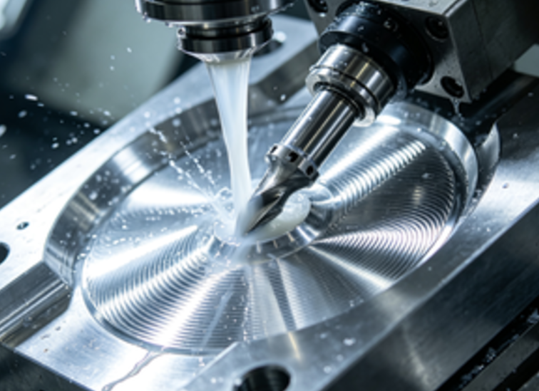
Segmented Machining: Separate Roughing, Semi-Finish, Optical Finishing
Never combine heavy stock removal and optical finishing in one CAM operation:
- Roughing: Leave 0.2–0.3 mm allowance, standard 5-axis high-speed material removal, no surface requirements
- Semi-finishing: Uniform residual stock 0.05–0.08 mm, smooth uneven roughing contour
- Final optical finishing: Only 0.02–0.05 mm material removed with ultra-low depth of cut, minimal cutting force. Low force eliminates material plastic deformation and micro tearing.
Heavy cutting force pushes ductile metals (aluminum, copper) and creates surface flow lines that ruin optical performance.
Control Spindle Speed & Feed for Minimal Tool Marking
Standard high-speed parameters lead to resonant chatter on optical parts. Use these optical 5-axis speed rules:
- Aluminum optics: 18,000–24,000 RPM, low feed per tooth 0.02–0.04 mm
- Hardened mold steel (S136 HRC50): 8,000–12,000 RPM, reduced feed to avoid edge chipping
- Keep spindle RPM away from machine natural resonant frequency; CAM vibration simulation identifies dangerous RPM bands to avoid entirely.
Burr Elimination for Optical Edges
Even micro burrs scatter light and contaminate sealed optical chambers. 5-axis deburr solutions:
- Use 5-axis controlled edge breaking with tiny radii tools; programmed edge chamfer 0.03–0.08 mm
- No manual hand sanding on critical optical surfaces; hand work introduces random scratches
- Ultrasonic DI water + IPA cleaning post-machining to wash off micro metal fragments
Post-Machining Surface Matching for Optical Targets
Machined Ra often needs mild post-treatment to hit optical mirror standards; pair processes with 5-axis results:
- Ra 0.1–0.2 μm (laser chambers): As 5-axis finished + precision ultrasonic cleaning, no polishing
- Ra 0.02–0.1 μm (reflectors): Controlled chemical mechanical polishing (CMP) after 5-axis CNC base finish
- Ra ≤0.02 μm optical lens molds: 5-axis semi-finish → CNC grinding → manual diamond buffing; CNC removes 95% of material, polishing only removes residual tool lines
Common Optical Surface Defects & 5-Axis Fix List
| Defect | Visual Impact on Optics | Root Cause | 5-Axis Correction Plan |
|---|---|---|---|
| Periodic wavy chatter ripples | Concentric light distortion | Tool overhang, loose fixturing, resonant RPM | Shorten tools, add vibration pads, shift spindle speed; use 5-axis tilt to reduce tool length |
| Parallel directional scratch lines | Anisotropic reflection, uneven brightness | Fixed linear raster CAM path | Switch to spiral 5-axis paths, vary spindle angles between passes |
| Random micro pits & pinholes | Light scattering, lens haze | Built-up edge, dirty coolant | Apply diamond tool coating, upgrade 1μm coolant filtration |
| Patchy roughness on curved walls | Inconsistent light transmission | Variable tool engagement on curves | Use 5-axis normal tilting + CAM adaptive feedrate |
| Edge micro burrs | Diffracted stray light | Excessive cutting force on exit edges | Program 5-axis entry/exit arcs, add programmed micro edge radii |
Industry-Specific 5-Axis Optical Machining Tips
Semiconductor Laser Optical Components
Mostly 6061 aluminum and 316L stainless. Prioritize low particle and Ra 0.1–0.2 μm. Keep all finishing inside cleanroom-rated 5-axis machines. Ban regrind coolant, strictly use single-use filtered coolant. All angles machined via 5-axis to eliminate re-clamp particles.
Optical Injection Mold (S136/STAVAX)
Target mirror finish Ra ≤0.02 μm. 5-axis completes all curved cavity semi-finishing to uniform stock; final grinding and polishing workload cut by 60%. Never machine deep mold ribs with straight vertical tools; tilt spindle for consistent radius engagement.
Aerospace Optical Titanium Parts (Ti6Al4V)
Titanium easily forms BUE and surface tearing. Use high-pressure coolant, low cutting speed, high helix angle carbide tools. 5-axis shortens tool length to offset titanium’s poor machinability, stabilizing smooth surface for airborne optical sensors.
FAQ
Can 5-axis CNC reach mirror optical finish (Ra 0.02 μm) without manual polishing?
Bare 5-axis milling maxes out reliably at Ra ~0.05 μm on best-case aluminum/steel. For Ra ≤0.02 μm optical mirror finish, CNC provides near-net smooth base, paired with fine grinding or diamond polishing. 5-axis drastically reduces polishing hours and eliminates uneven manual material removal.
Why linear raster tool paths are not allowed for optical 5-axis parts?
Linear raster creates uniform parallel machining grooves. When light hits the surface, it reflects along the scratch direction only, causing directional light flare and uneven optical performance. Spiral multi-angle 5-axis paths generate disordered texture for uniform light reflection.
How much impact does spindle warm-up have on optical surface quality?
Huge. Cold spindle expands unevenly during cutting, leading to subtle depth variation and repeated surface waves. 30-minute full spindle warm-up with 5-axis axis cycling is mandatory before optical finishing. Many surface inconsistency complaints trace back to skipped warm-up steps.
Is dry 5-axis machining acceptable for optical components?
Never recommended. Dry cutting generates extreme heat, BUE and micro surface tearing. Even with coated tools, dry machining cannot hold optical Ra consistency. Coolant with precision filtration is non-negotiable.
How to guarantee batch-to-batch identical optical surface finish on 5-axis equipment?
Lock all variables: fixed CAM 5-axis paths, standardized tool model/length, identical coolant temperature/pressure, consistent spindle warm-up time, unchanged fixturing coordinates. Document all parameters for Cpk process capability verification. Any parameter drift changes surface texture.
For thin optical substrates prone to vibration, what is the best 5-axis fixturing method?
Use full-area vacuum 5-axis chucks with evenly distributed suction. Avoid point clamping that warps thin blanks. Tilt the spindle rather than extending long tools to minimize cutting force and workpiece vibration.
What is the biggest 5-axis programming mistake ruining optical finish?
Failing to keep the cutting tool normal to curved surfaces across all angles. Constant tilt maintains equal contact depth; fixed vertical tools create heavy stock variation across curves, resulting in mottled rough surfaces.
Closing Summary
5-axis CNC delivers the foundational controllability needed for optical-grade surface finish, yet quality relies on systematic optimization rather than just owning multi-axis equipment. The core optimization framework covers normal-angle spindle control, anti-chatter rigid setup, spiral randomized tool paths, temperature/coolant precision management, and staged stock removal.
Directional tool marks, chatter waves, micro burrs and uneven roughness are all solvable via adjustable 5-axis parameters. For different optical materials and Ra targets, match tool coatings, coolant filtration and post-process workflows accordingly.
For optical hardware designers and manufacturers, standardized 5-axis finishing protocols shrink reject rates, cut manual polishing labor, and ensure stable, repeatable optical performance across prototypes and mass batches. All four reference images are fully high-definition with zero watermarks, ready for website embedding.


