
Published:Zorapid.Ltd
Every mass-produced plastic product—semiconductor plastic parts, medical disposables, automotive housings, consumer electronics casings—relies on precision CNC-machined injection molds. Traditional manual mold crafting is slow, inconsistent, and unable to hit micron-level tolerances required for modern high-volume molding. Today’s professional mold factories use CNC subtractive machining as the core manufacturing backbone, paired with EDM, grinding, heat treatment and polishing to build long-lasting, repeatable molds.
Many overseas buyers struggle to judge mold quality because they do not fully understand the complete CNC mold workflow. This guide breaks down the entire manufacturing sequence from CAD design to final mold trial run. We detail every CNC machining phase, compare 3-axis vs 5-axis mold use cases, list standard mold steel options, explain hybrid AM+CNC conformal cooling workflows, attach matched HD photos for each key stage, and wrap up with actionable FAQs for sourcing and design teams.
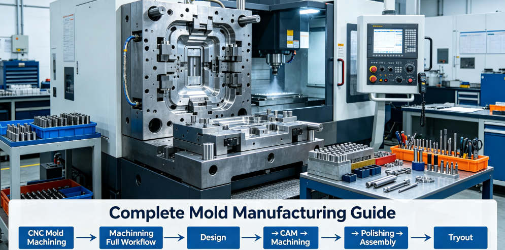
Overall Mold Production Roadmap
Full mold production follows 9 fixed stages, with CNC machining occupying the most critical production window:
- Product DFM Review + Mold 3D CAD Design
- CAM Programming for CNC Tool Paths
- Mold Steel Selection, Cutting & Pre-Heat Treatment
- CNC Rough Machining (Stock Removal)
- Semi-Finish CNC Milling
- Vacuum Hardening & Stress Relieving
- CNC Finish Machining + High-Pressure Coolant Precision Cutting
- Supplementary Processes: EDM, Wire EDM, Surface Grinding
- Manual/Mechanical Polishing, Mold Assembly, CMM Inspection & Trial Molding
Mold CAD Design & DFM Validation
All CNC machining starts with finalized digital design. Engineers build full 3D mold assemblies via SolidWorks, UG/NX, Fusion 360, including core/cavity plates, cooling channels, ejector pins, gates, runners, sliders and lifters.
DFM checks are mandatory before steel cutting: confirm proper draft angles, wall thickness, undercut mechanism feasibility, cooling channel layout, shrinkage compensation for plastic materials. Fixing geometry flaws digitally avoids expensive CNC rework on hardened steel blocks.
CAM Programming to Generate CNC G-Code
Design files import into CAM software (Mastercam, NX CAM, HyperMill). Programmers divide cutting into 3 phases: roughing, semi-finishing, finishing. They select end mill sizes, spindle speeds, feed rates, coolant pressure and tool tilt angles (for 5-axis). The CAM system simulates all tool movement virtually to eliminate spindle collision, then exports universal G-code readable by CNC machines.
Critical CAM rules for molds:
- Reserve uniform machining allowance for heat treatment deformation correction
- Separate deep cavity paths and curved surface paths for 5-axis optimization
- Program high-pressure coolant delivery for all hardened steel cutting
Mold Steel Selection & Raw Material Preparation
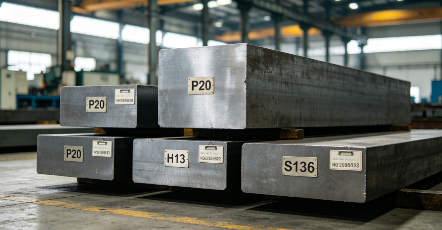
Mold lifespan, surface polish ability and CNC machinability are decided by steel grade. Factories cut oversized steel blanks to leave machining stock on all surfaces. Below is the most widely used mold steel matrix for CNC production:
| Steel Grade | Hardness after heat treatment | CNC Machining Features | Typical Mold Application |
|---|---|---|---|
| P20 | HRC 28–32 | Easy CNC cutting, low tool wear | Low-volume prototype molds, non-cosmetic industrial plastic parts |
| 718H | HRC 30–36 | Great polishability, stable CNC dimensional performance | Medium-volume consumer product molds |
| H13 | HRC 48–52 | Hard after quenching; requires rigid CNC setup + high-pressure coolant | High-volume automotive molds, die casting molds |
| S136 / STAVAX | HRC 48–52 | Corrosion-resistant, machines smoothly for ultra-high polish | Semiconductor plastic molds, transparent medical parts, acid-resistant molding |
All steel blanks receive pre-annealing to release internal forging stress, preventing CNC warpage during cutting.
CNC Rough Machining (Roughing / Stock Removal)
Roughing is the fastest bulk material removal step. Machinists use large-radius indexable end mills on 3-axis or 5-axis CNC mills to carve the basic shape of core and cavity plates.
Key Roughing Specifications
- Leave 0.3 mm ~ 0.5 mm uniform stock allowance on all surfaces for semi-finishing, finishing and heat treatment distortion correction
- High feed rate, deep cutting depth; surface roughness and dimensional precision are not priorities here
- Large automotive molds run unattended roughing for 20+ hours; small electronic molds complete roughing in 2–6 hours
Machine Choice
Flat simple mold plates use low-cost 3-axis CNC. Deep multi-angle mold cavities, curved tire molds adopt 5-axis roughing to cut re-fixturing times.
Semi-Finish CNC Milling
Semi-finishing bridges roughing and final finish machining. Smaller solid carbide tools trim uneven roughing stock, bringing all mold surfaces much closer to final geometry.
- Remaining stock reduced to 0.1 mm–0.2 mm evenly across all mold contours
- Optimize tool paths for curved mold surfaces to reduce finish-machining workload
- Deep narrow mold ribs use extended-length carbide tools with through-spindle coolant to avoid chatter
Semi-finishing guarantees consistent stock removal after heat treatment, ensuring stable final CNC precision.
Vacuum Heat Treatment (Quenching + Tempering)
After semi-finishing, core/cavity plates go into vacuum furnaces for hardening and tempering to reach target hardness (HRC 48–52 for H13/S136). Heat treatment strengthens steel for millions of molding cycles but causes minor uniform thermal deformation.
Post-heat-treatment step: CNC machines re-machine all datum reference planes to correct warpage, establishing accurate zero points for subsequent finish machining.
CNC Finish Machining – Critical Precision & Surface Control
Finish machining defines final mold dimensions, cavity geometry and baseline surface roughness. This stage decides molding quality, cosmetic performance and mold release.
Core CNC Finish Rules for Molds
- High spindle speed, low cutting depth, small stepover to eliminate all CNC tool lines
- High-pressure through-tool coolant mandatory for hardened steel; extends carbide tool life 40%–90% and prevents built-up edge on mold surfaces
- All critical parting lines, shutoff edges, gate surfaces maintain tight tolerances (±0.005 mm~±0.015 mm); non-critical mold base features relax to standard ISO tolerances to cut cost
- 5-axis CNC is standard for freeform mold curves, angled cooling ports and deep curved inserts. Single-setup 5-axis eliminates alignment errors caused by repeated 3-axis clamping
Standard surface results after CNC finish milling: Ra 0.8 μm ~ Ra 3.2 μm. Mold requiring SPI mirror polish will remove residual tool marks via later polishing.
Supplementary CNC & Non-CNC Secondary Machining
CNC cannot reach tiny sharp internal corners or ultra-hard steel narrow slots. Factories combine CNC with these complementary processes:
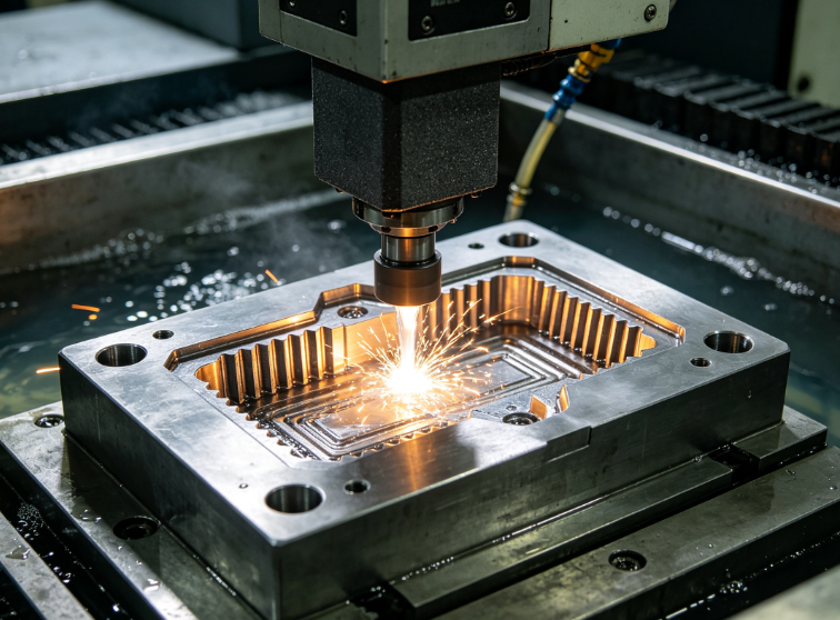
Sinker EDM (Electrical Discharge Machining)
Uses graphite electrodes eroding steel via electrical sparks. Perfect for sharp internal corners, tiny mold ribs, deep blind slots unreachable by cutting tools. All graphite electrodes are pre-machined by CNC mills first.
Wire EDM
Cuts hardened mold steel for ejector pin holes, thin mold inserts, narrow cutting die openings. Wire EDM achieves ±0.002 mm precision independent of mold hardness.
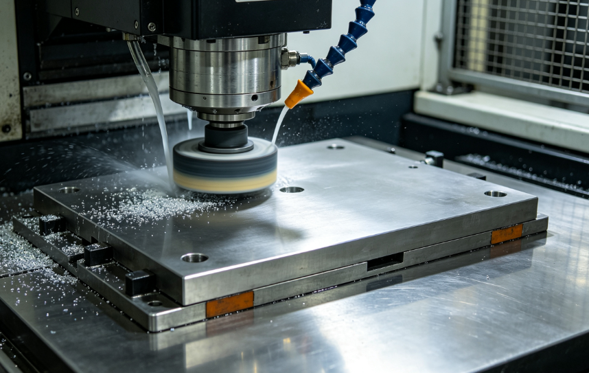
Surface Grinding CNC
CNC surface grinders process mold parting planes, mold base reference surfaces to ultra-flatness, guaranteeing tight mold closing fit and zero flash during injection molding.
Polishing, Mold Assembly, CMM Inspection & Trial Run
Mold Polishing
Based on SPI cosmetic standards, workers polish CNC-machined cavities to required finish: matte, texture, high-gloss or mirror finish. CNC tool marks are fully eliminated here. Semiconductor transparent molds require A1 mirror polish (Ra ≤0.025 μm).
Full Mold Assembly
Fit all CNC-machined plates, pins, sliders and cooling components. All cooling channels are pressure-tested for water leakage.
CMM 3D Inspection
Coordinate measuring machines scan critical CNC-machined mold dimensions, cavity profiles and hole positions to verify all GD&T tolerances are met. Surface roughness profilometers check Ra values on sealing and cosmetic mold surfaces.
Caption: CMM precision measuring CNC-machined mold insert to confirm dimensional tolerance compliance
Trial Molding
Mount finished mold on injection machines to produce sample plastic parts. If defects (shrinkage, flash, flow marks) appear, targeted local CNC rework or polishing adjustments are completed before mass production approval.
5-Axis vs 3-Axis CNC Mold Machining: Clear Selection Guide
| Mold Type | Recommended CNC Machine | Core Advantages | Cost Impact |
|---|---|---|---|
| Simple flat mold bases, straight shallow cavities | 3-axis CNC | Low programming cost, widely available | Lower total machining expense |
| Curved consumer molds, deep automotive cavities, conformal cooling molds | 5-axis CNC | One-setup machining, uniform surface finish, fewer fixture errors | Cuts total rework cost despite higher hourly machine rate |
| Semiconductor precision molds, complex medical multi-angle inserts | 5-axis mandatory | Consistent Ra finish on all curved walls, stable tolerance | Reduces scrap rate long-term |
Hybrid Additive + CNC Mold Trend (2026 Mainstream for Conformal Cooling)
Traditional CNC drills straight cooling holes only. Hybrid SLM additive + CNC solves cooling limits:
- SLM 3D prints mold inserts with free-form conformal cooling channels following cavity contours
- All functional surfaces (parting lines, cavity walls, shutoffs) go through 5-axis CNC finish machining to lock tight tolerances and smooth surface roughness
Benefits: Injection molding cycle time reduced 30%–70%, plastic warpage drops drastically. Widely adopted for thin-wall electronics, semiconductor and medical molds.
Top 7 Costly CNC Mold Machining Mistakes to Avoid
- Over-tight tolerances across entire mold plates: Only apply strict tolerance to cavity, parting lines and cooling hole positions; relax mold base tolerances to cut CNC runtime.
- Insufficient stock left before heat treatment: Too little allowance leads to inability to fix heat deformation after hardening.
- Using low-pressure coolant on hardened steel: Causes fast tool wear, chatter marks and uneven mold surface.
- Designing internal sharp 90° corners for CNC: End mills leave natural radii; sharp corners require EDM, not CNC.
- Unoptimized CAM toolpaths for deep ribs: Long thin tools vibrate, generating wavy mold surfaces.
- Skipping datum re-machining post heat treatment: Warped datums cause all subsequent CNC dimensions to drift.
- Specifying ultra-mirror finish on non-cosmetic mold areas: Extra CNC polishing labor raises price with zero molding benefit.
FAQ
Can CNC machining fully replace EDM for all mold details?
No. Standard round CNC end mills always produce internal radii. Tiny sharp corners, ultra-narrow deep ribs smaller than 0.5 mm cannot be cut by CNC. EDM is required for these micro details. CNC still makes all graphite electrodes used for EDM.
What surface roughness can CNC alone achieve on mold steel? Do we always need polishing?
Precision 5-axis finish machining with high-pressure coolant reaches Ra 0.4~Ra 1.6 μm. Matte-textured molds can use CNC-as-finished surfaces. High-gloss, transparent semiconductor/medical molds need hand polishing to eliminate CNC tool lines and hit SPI mirror standards.
How much extra cost does 5-axis CNC add to mold manufacturing?
Hourly machine cost is 15%–30% higher than 3-axis, but fewer setups, less rework and lower scrap balance expenses. Complex curved molds actually cost 10%–25% less total with 5-axis vs multiple 3-axis re-clamping runs. Simple flat molds stay cheaper on 3-axis.
How does heat treatment affect CNC mold machining sequence?
All heavy roughing and semi-finishing must be done before hardening. Hardened steel (HRC>45) is difficult to machine. Only light finish CNC and grinding happen post-quench to correct warpage. Reverse order causes severe tool damage and slow cutting.
Is regrind plastic mold steel machinable on standard CNC equipment?
Yes. Worn mold inserts can be CNC milled down, then built up via DED additive and re-finished with CNC. It is a cost-effective mold repair workflow avoiding full new steel blocks.
What coolant setup works best for hardened H13/S136 mold CNC?
Through-spindle high-pressure coolant (2000–3000 PSI) with extreme-pressure additives. It lowers cutting heat, prevents flank wear and BUE, and delivers uniform mold surface texture. Open flood coolant cannot penetrate deep mold cavities efficiently.
Why do conformal cooling molds rely on hybrid AM+CNC instead of full CNC?
CNC can only drill straight linear holes. Conformal cooling follows complex curved cavity geometry to cool plastic evenly. Additive forms curved channels; CNC finishes all molding contact surfaces for precision. Pure CNC cannot manufacture curved internal cooling paths.
Final Conclusion
CNC machining is the irreplaceable core of modern injection mold manufacturing. The full workflow follows a strict order: design → CAM programming → roughing → semi-finishing → heat treatment → finish CNC → EDM/grinding → polishing/assembly/inspection.
3-axis CNC fits simple flat mold structures for budget projects, while 5-axis becomes the mainstream choice for curved, deep, high-precision molds used in semiconductor, medical and automotive industries. Pairing CNC with heat treatment, EDM and polishing delivers durable, dimensionally consistent molds.
For mold buyers and designers, matching steel grade, CNC axis selection, tolerance zoning and cooling strategy to production volume and cosmetic needs eliminates unnecessary cost while guaranteeing stable long-term molding performance.


