
Published:Zorapid.Ltd
If you machine custom racing auto parts—Formula car wheel hubs, suspension uprights, turbo manifolds, brake caliper housings, lightweight transmission components, or aerodynamic PEEK duct inserts—you live by one critical metric: 5-axis cycle time.
Motorsport operates on tight deadlines. Teams need prototype iterations in days, not weeks, and low-volume batch runs can’t waste hours of expensive 5-axis machine capacity. Slow cycle times kill profitability, delay vehicle testing, and bottleneck your entire motorsport manufacturing workflow.
Racing components bring tricky geometry: deep thin-wall pocketing, complex 3D aerodynamic contours, compound angled mounting faces, tight weight-saving cutouts, and hard-to-machine titanium alloys. Standard generic 5-axis CAM settings deliver slow, inefficient tool paths.
This guide breaks down proven, shop-tested 5-axis cycle time optimization strategies built exclusively for racing auto parts. We cover CAM programming, tool selection, workholding, speed/feed tuning, single-setup workflows, and a complete FAQ answering the most common motorsport CNC pain points. Every tip cuts real minutes off your run time without sacrificing the ultra-tight tolerances racing hardware demands.
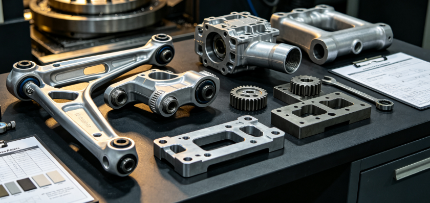
Unique Challenges Machining Racing Auto Parts on 5-Axis
Before optimizing cycle time, address the inherent geometry and material hurdles unique to motorsport components:
- Complex freeform 3D contours Suspension uprights, wheel hubs and aerodynamic ducts require continuous simultaneous 5-axis movement; poorly written tool paths create constant axis jerking and slow feed rates.
- Extensive lightweight pocketing & thin walls Deep, large-area material removal for weight reduction generates long roughing cycles, plus thin sections risk chatter that forces slower finishing speeds.
- Mixed tough materials 6061/7075 aluminum for most structural race parts, Ti-6Al-4V for high-load suspension, carbon-filled PEEK for lightweight non-metallic ducting—each needs separate speed/feed tuning.
- Multiple compound-angle features Mounting bosses, caliper mounting faces, and fastener holes sit at irregular angles; multi-setup 3-axis machining adds hours of re-fixturing labor.
- Small low-volume batches + frequent design revisions Racing teams iterate CAD constantly. You can’t rely on long optimized mass-production cycles; every new prototype needs fast CAM setup and short machining runs.
10 Practical 5-Axis Cycle Time Optimization Rules for Race Components
Rule 1: Machine Every Feature in One Single 5-Axis Setup
The biggest cycle time waste comes from removing, re-clamping, and re-probing parts for secondary operations. Program all roughing, finishing, angled drilling and contouring in one 5-axis fixture.
Time saving: Eliminate 30–60 minutes of re-fixturing, probing and alignment per race component.
Rule 2: Split Roughing & Finishing into Separate Tool Path Strategies
Don’t use small finishing end mills for bulk stock removal. Deploy large high-feed roughers first to hog out lightweight pockets fast, then switch to smaller tools only for tight radii and fine contours.
For racing billets, remove 80% of excess material in fast roughing passes to minimize slow finishing time.
Rule 3: Use Simultaneous 5-Axis for Contours, Indexed 5-Axis for Holes & Bosses
Contoured aerodynamic surfaces run faster with continuous simultaneous 5-axis movement. For angled drilling, tapping and flat boss faces, lock rotary axes in indexed positions—this reduces axis vibration and lets you run higher feed rates.
Rule 4: Minimize Tool Change Count to Cut Idle Spindle Wait Time
Consolidate operations to reduce tool swaps. Match tools to cover multiple feature sizes: use a single high-feed mill for all large pocket roughing, one ball nose for all standard radii, one drill size for common fastener holes.
Every tool change adds 10–30 seconds of dead cycle time; cutting 10 swaps saves multiple minutes per part.
Rule 5: Apply Rest Machining to Avoid Re-Machining Already Cleared Stock
Standard roughing recuts material already removed by larger tools. Enable rest machining in your CAM software to skip cleared pockets entirely. This slashes roughing cycle time on deeply pocketed racing hubs and uprights by 20%+.
Rule 6: Optimize Lead-In / Lead-Out Moves to Eliminate Slow Ramp Downs
Default CAM small ramp angles slow down roughing. For open racing pocket geometry, use high-angle helical entry or direct plunge zones with dedicated plunge tools. Avoid tiny incremental ramps that drag out cycle time.
Rule 7: Control Thin-Wall Chatter to Maintain Maximum Feeds
Racing parts rely on ultra-thin walls for weight savings. Add temporary support tabs during roughing to suppress vibration—this lets you run 30–50% faster finishing feeds without surface defects. Remove tabs in a quick secondary operation after all critical machining.
Rule 8: Limit Rotary Axis Full Rotations That Add Unnecessary Travel
Program CAM to rotate rotary axes the shortest path possible. Avoid full 360° spins between features; small angular jumps cut non-cutting rapid travel time drastically on complex multi-angle race parts.
Rule 9: Batch Multiple Small Race Components on One Fixture Plate
For small brackets, clevises or duct inserts, fixture 4–8 identical billets on a single tombstone plate. The machine runs continuous roughing/finishing without manual reloads, spreading spindle startup and probe time across multiple parts.
Rule 10: Pre-Stress Relieve Billet Stock Before 5-Axis Finishing
If roughing leaves residual material stress, you’re forced to run slow, light finishing passes to counteract warpage. Stress-relieve aluminum/titanium blanks post-roughing. Finishing can then run at full programmed feeds without dimensional risk.
Tooling Strategies to Slash Machining Minutes
Tool selection directly dictates how fast you can remove stock on racing 5-axis parts:
- High-Feed End Mills for Rough Pocketing (Top Time Saver) High-feed cutters with rounded geometries operate at 2–4x faster feed rates than standard square end mills for large lightweight pockets. Ideal for 7075 aluminum wheel hubs and uprights.
- Solid Carbide Multi-Flute Ball Noses for Contour Finishing More flutes enable higher surface speed feeds on aerodynamic curved surfaces; reduce finishing cycle time by 25% vs 2-flute ball tools.
- Short, Rigid Tool Holders to Eliminate Chatter Long tool overhangs force slower feeds for deep racing manifold pockets. Use shrink-fit holders and shortest possible tool lengths to maintain maximum cutting speeds.
- Specialty Titanium Cutters for Ti Suspension Parts Ti-6Al-4V generates high heat; coated carbide tools with chip-breaker geometry boost metal removal rates without premature tool wear.
- Modular Drill/Tap Heads for Compound-Angled Holes Combined drill tap tools cut separate drilling and tapping cycles into one single pass on race mounting bosses.
Workholding & Single-Setup Efficiency Hacks
Poor fixturing creates extra cycle time and limits aggressive machining parameters:
- Use low-profile vacuum chuck plates for thin aluminum racing billets; full part surface clamping eliminates vibration for high-speed roughing.
- Custom low-profile tombstone fixtures hold multiple parts without blocking 5-axis rotary travel limits.
- Design fixture cutouts that fully clear all part geometry—no manual repositioning mid-cycle.
- Install machine probe cycles for one-click datum setting; automatic probing cuts manual setup time and enables consistent batch runs.
- Avoid heavy solid fixture blocks that limit rotary axis movement; lightweight aluminum fixtures maximize axis travel range.
CAM Programming Tweaks Built for Motorsport Geometry
These CAM parameter adjustments deliver immediate cycle time reduction without sacrificing surface finish:
- Increase stepover for roughing (stay within tool manufacturer safe limits) to remove more material per pass.
- Enable constant chip load to maintain consistent feed rates regardless of part contour shape.
- Shorten rapid travel distances by reordering tool path sequence to minimize rotary axis movement.
- Turn off unnecessary fine smoothing on non-critical internal pocket surfaces; reserve tight tolerance smoothing only for mating sealing faces.
- Use trochoidal milling for deep narrow slots common on brake caliper housings—reduces tool load and allows faster feeds.
- Reduce idle rapid traverse delay values in machine controller parameters for fast axis repositioning.
Material-Specific Speed & Feed Tuning (Racing Common Materials)
Optimize parameters per material to hit maximum metal removal rates safely:
7075-T6 Aluminum (Wheel Hubs, Uprights, Control Arms)
- Rough high-feed mill: 8,000–12,000 RPM, 6–10 m/min feed
- Thin-wall finishing: 6,000–9,000 RPM, 3–5 m/min feed
- Biggest gain: Aggressive trochoidal roughing with high-feed cutters
Ti-6Al-4V Titanium (High-Load Suspension Components)
- Lower spindle speeds 1,200–2,800 RPM, moderate feed rates
- Small stepdowns to control heat buildup; avoid heavy roughing passes
- Use flood high-pressure coolant to maintain consistent cutting speeds
Carbon-Filled PEEK (Aero Ducts, Lightweight Inserts)
- Lower RPM to prevent melting, sharp polished tool edges
- High feed finishing to reduce contact time between tool and plastic surface
Common 5-Axis Mistakes That Blow Up Race Part Cycle Times
- Running small finishing tools for bulk rough pocket removal
- Multiple separate setups instead of single-operation 5-axis programming
- Excessively small stepover values for non-critical rough stock
- Long tool overhang causing chatter, forcing reduced feed rates
- Unoptimized tool path order with constant large rotary axis rotations
- Skipping stress relief, requiring slow light finishing passes to counter warpage
- Too many unique tool sizes leading to frequent, time-consuming tool changes
- Default CAM small ramp angles for all pocket entry moves
- Over-smoothed tool paths on non-visible internal lightweight cutouts
- Single-part fixturing when multiple small race components can nest on one plate
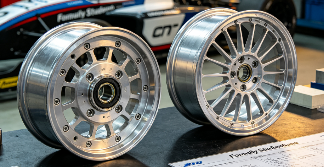
Real-World Optimization Case: Formula Student Wheel Hub
Original Baseline Process
- Material: 7075-T6 aluminum wheel hub, extensive lightweight pocketing + compound angle bolt bosses
- Old workflow: 3 separate 5-axis setups, standard square end mill roughing, generic CAM parameters
- Total original cycle time: 1 hour 42 minutes per unit
Implemented 5-Axis Optimization Changes
- Redesigned fixture for full single-setup machining
- Swapped to high-feed roughing mills + rest machining enabled
- Consolidated tool count from 12 down to 7 tools to cut swaps
- Stress-relieve billet post-roughing for full-speed finishing
- CAM reordering to minimize large rotary axis rotations
- Added temporary thin-wall support tabs to eliminate chatter slowdowns
Final Result
- Optimized cycle time: 58 minutes per hub
- Total time reduction: 44 minutes per component (43% cycle time cut)
- No loss of dimensional tolerance or surface finish quality
- Batch of 8 hubs now finishes in one full machine shift vs two shifts previously
FAQ
What delivers the largest single cycle time cut on racing 5-axis components?
Combining single-setup 5-axis machining and high-feed rough milling. Eliminating multiple re-fixturing removes 30–60 minutes of dead time, while high-feed roughers slash bulk stock removal time by half on heavily pocketed lightweight race parts.
Can I run faster feeds on thin-wall racing parts without dimensional defects?
Yes, with temporary support tabs during roughing. Tabs suppress vibration and chatter, allowing full programmed feed rates. Remove tabs in a quick final pass after all critical geometry is machined. Skipping tabs forces you to drop feed speeds drastically to avoid wall deflection.
Is simultaneous 5-axis always faster than indexed 5-axis for racing parts?
Not entirely. Curved aerodynamic contours run faster with continuous simultaneous movement. For flat angled bosses, drilling and tapping, lock rotary axes in indexed positions—this reduces axis jerk and vibration to support higher feed rates. Mix both modes in one program for maximum efficiency.
How much cycle time can rest machining save on deeply pocketed motorsport billets?
20–35% roughing time reduction. Rest machining skips areas already cleared by larger roughing tools, eliminating redundant recutting of empty pocket space common on wheel hubs and suspension uprights.
Does batch nesting multiple small race brackets on one fixture improve cycle time?
Dramatically. Probing, spindle warm-up and fixture clamping overhead is spread across all nested parts. A plate of 6 small clevises cuts per-unit idle setup time by over 70%.
What’s the biggest CAM programming mistake that slows racing 5-axis machining?
Unoptimized tool path sequencing that forces constant large rotary axis rotations between features. Reorder operations to machine all features on similar angular positions consecutively, minimizing full rotary swings.
Can cycle time optimization risk losing the tight tolerances racing components require?
Properly implemented optimization does not impact tolerance. All speed/feed increases target roughing and non-critical geometry; mating sealing surfaces and mounting datums retain conservative finishing parameters. Stress relief and rigid workholding eliminate warpage risks from faster roughing passes.
How do I optimize 5-axis cycle time for titanium suspension race parts?
Use dedicated titanium coated carbide tools, small depth-of-cut roughing passes, high-pressure flood coolant, and trochoidal milling to control heat buildup. Avoid aggressive high-feed parameters used for aluminum; titanium requires moderate consistent feeds to prevent tool failure.
Should I stress-relieve billets to speed up finishing cycles?
Absolutely. Unrelieved aluminum/titanium retains internal roughing stress that warps thin walls during finishing. Stress-relieved stock lets you run full-speed finishing passes without slowing feeds to compensate for shifting geometry.
For low-volume racing prototype batches, is single-setup 5-axis still worth programming time?
Yes. Even for 1–2 prototype units, the time saved skipping re-fixturing, re-probing and re-alignment far outweighs minor extra CAM programming effort for full single-setup tool paths.
Quick 5-Axis Cycle Time Reduction Checklist (Shop Floor Use)
Fixture & Setup Optimization
All part geometry machined in one single 5-axis setup
Multiple small race components nested on one fixture plate
Low-profile rigid holders to avoid long tool overhang chatter
Automatic probing cycle pre-programmed for fast datum setting
Tooling & Roughing Efficiency
High-feed end mills deployed for all large pocket roughing
Tool count consolidated to minimize time-consuming tool swaps
Rest machining enabled in CAM to skip pre-cleared stock
Temporary support tabs added to thin-wall lightweight sections
CAM Programming Parameters
Shortest rotary axis travel path selected for all moves
Aggressive high-angle helical entry ramps instead of tiny incremental ramps
Constant chip load enabled to maintain consistent maximum feeds
Non-critical surfaces set to wider roughing stepover
Material & Stress Control
Billet stock stress-relieved post roughing before finishing
Material-specific speed/feed tables applied (Aluminum / Ti / PEEK)
High-pressure coolant active for titanium hard material runs
Closing Wrap-Up
5-axis cycle time optimization for racing auto parts isn’t just cranking up spindle speed and feed rates—it’s a balanced workflow of single-setup fixturing, smart tool selection, CAM path refinement, chatter control, and material-specific tuning.
Motorsport’s unique lightweight pocketed geometry, mixed hard materials and frequent prototype iterations make inefficient machining costly and time-consuming. By implementing these shop-proven strategies, you can slash cycle times by 30–45% on wheel hubs, suspension uprights, brake components and aerodynamic inserts while holding the precision racing teams rely on.
If you’re looking to optimize your existing 5-axis CAM programs for motorsport parts, send over your racing component CAD files for a free cycle time reduction DFM & programming review. Our CNC engineers will flag slow tool paths and deliver parameter tweaks to cut run time immediately.


