
Published:Zorapid.Ltd
If you design industrial equipment, EV packs, medical diagnostic devices, semiconductor tools, or racing hardware, precision custom sheet metal is almost always your go-to structural housing solution.
Unlike rough general sheet metal work, precision fabrication holds strict dimensional tolerances, consistent bend angles, leak-tight welds, and uniform surface quality—critical for parts that mate with CNC machined frames, vacuum chambers, PEEK internal components, or battery module assemblies.
Many engineering teams waste budget and hit production delays because they don’t understand precision sheet metal’s process limits, material rules, or DFM standards. This complete guide walks you through every stage of precision sheet metal production, from material selection and CAD design to laser cutting, CNC bending, welding, finishing, and quality inspection. We also break down cost drivers, common precision defects, and a full FAQ answering the most frequent sourcing questions for global industrial OEMs.
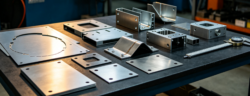
Core Materials for Precision Sheet Metal Fabrication
Material choice directly impacts achievable tolerances, weight, corrosion resistance, and fabrication difficulty. Below are the most widely used grades for precision custom parts:
Aluminum Alloys (Lightweight EV & Diagnostic Housings)
- 5052-H32: Balanced formability, moderate strength, ideal for enclosures, battery tray frames, easy bending
- 6061-T6: Higher rigidity, weldable, used for structural precision frames; hard anodize compatible
- 3003: Soft alloy for complex deep bending, low-cost non-load-bearing covers
Stainless Steel (Semiconductor, Medical, UHV Equipment)
- 304L: General corrosion resistance, cleanroom compatible, good for lab equipment housings
- 316L: Superior resistance to chemical reagents, plasma, salt exposure; mandatory for etch tool enclosures
- 316L VIM-VAR: Low carbon low outgassing grade for vacuum-adjacent sheet metal components
Cold Rolled Steel (Low-Cost Industrial Structural Frames)
- SPCC: Budget structural supports, always requires powder coating to prevent rust; not recommended for medical/semiconductor clean environments
Specialty Materials
- Galvanized steel: Outdoor industrial enclosures, avoid welding (zinc fumes & coating failure)
- Copper sheet: Thermal shielding, heat spreaders for battery cooling systems
Full Step-by-Step Precision Fabrication Workflow
Every precision sheet metal order follows this standardized quality-controlled sequence to guarantee consistent tight tolerances:
- CAD DFM Review Manufacturer engineers audit drawings for bend relief, minimum hole sizes, tolerance over-specs, and weld accessibility before cutting stock.
- Raw Material Prep Flat sheet stock cut to master blank sizes, deburred, cleaned to remove surface oil and oxidation.
- High-Precision Laser Cutting / CNC Punching All cutouts, mounting holes, weight relief cutouts processed with ±0.02mm positional accuracy.
- CNC Precision Bending Program-controlled press brakes with angle compensation to lock repeatable bend tolerances across batches.
- Secondary Forming Roll forming, hemming, embossing, countersinking for mounting hardware.
- Precision Welding & Assembly TIG / laser welding for leak-tight, low-distortion precision joints; spot welding for lightweight assemblies.
- Deburr & Edge Finishing Vibratory finishing, micro-brush deburring to eliminate sharp edges without distorting thin sheet geometry.
- Surface Treatment Anodize, powder coat, electropolish, passivation, PTFE coating based on end-use requirements.
- Dimensional QC Inspection CMM, digital calipers, angle gauges, flatness testing for critical mating surfaces; batch certification reports provided.
- Cleanroom Packing & Shipping Anti-scratch film, nitrogen-sealed packaging for semiconductor/medical precision parts.
Key Precision Fabrication Processes Explained
1. Fiber Laser Cutting (Primary Precision Cutting Method)
Best for complex custom outlines, micro cutouts, vent slots, and precise hole patterns.
- Precision: ±0.015–0.03mm positioning tolerance
- Advantages: No tool wear, fast prototyping, sharp burr-free edges with clean laser beam
- Ideal for thin gauges 0.8–6mm aluminum/stainless sheet
2. CNC Punching
Cost-effective for high-volume runs with repeated standard holes, slots, and emboss features.
- Limitation: Limited custom complex contours; only standard tool shapes available
- Best for mass production equipment housings with uniform mounting hole grids
3. CNC Press Brake Bending (Most Critical Precision Step)
Programmable press brakes with real-time angle feedback control eliminate bend inconsistency—the #1 source of sheet metal precision errors.
- Precision standard: Bend angle ±0.3°, flange length ±0.05mm
- Critical design rules: Add bend relief notches to avoid material tearing and dimensional shift
4. Precision Welding Variants for Tight Tolerance Parts
- Laser Welding: Low heat input, minimal part warpage, ultra-thin seams for leak-tight EV tray frames and vacuum enclosures
- TIG Welding: Clean, high-strength joints for stainless medical/semiconductor parts; minimal spatter
- Spot Welding: Fast assembly for multi-layer aluminum sheet assemblies, no filler material
- Avoid MIG welding for high-precision components: Excess heat causes warpage and dimensional drift
5. Hemming & Roll Forming
Hem folded edges boost rigidity without adding thickness, eliminate sharp edges for safety-critical diagnostic equipment housings. Roll forming creates consistent curved profiles for ductwork and aerodynamic covers.
Critical Tolerance Standards for Precision Sheet Metal
Unlike solid CNC machined blocks, sheet metal has inherent forming limits—these are industry-standard precision specs for quality manufacturers:
Linear Dimensions (Flat Blank Features)
- General non-mating cutouts: ±0.05 ~ ±0.10 mm
- Critical mounting hole patterns / datum edges: ±0.02 ~ ±0.04 mm
Bend & Flange Tolerances
- Flange length: ±0.04 mm
- Bend angle: ±0.3°
- Inside bend radius deviation: ±0.2 mm
Flatness & Parallelism
- Large enclosure mating surfaces: ≤0.1mm flatness per 300mm span
Hole & Slot Precision
- Standard through holes: ±0.03 mm positional tolerance
- Long narrow vent slots: ±0.05 mm
Design Rules to Boost Precision & Cut Manufacturing Cost
Follow these DFM guidelines to avoid precision failures and reduce fabrication lead time & unit pricing:
- Standardize minimum bend radii Aluminum sheet: R ≥ material thickness; Stainless steel: R ≥ 1.5 × sheet thickness. Smaller radii cause cracking and inconsistent bend angles.
- Always add bend relief notches Without relief, sheet material stretches during bending, warping adjacent hole patterns and breaking tight tolerances.
- Separate critical tolerance zones from bend areas Holes within 3× material thickness of a bend will shift during forming; relocate datums and mounting points away from bend lines.
- Keep uniform sheet gauge across single assemblies Mixed thickness sheets require separate tooling and bending programs, increasing setup cost and alignment errors.
- Avoid overly thin unsupported panels Large flat thin sheet sections warp easily; add stamped reinforcing beads to improve flatness without thickening material.
- Design weld joints with accessible line of sight Hidden internal weld seams force slow, inconsistent manual welding that ruins dimensional precision.
- Limit tight tolerances only to mating surfaces Relax non-critical cosmetic cutouts to ±0.1mm to reduce laser cutting inspection time and unit cost.
Surface Finishes for Precision Sheet Metal Components
Each finish serves distinct precision industrial applications and impacts dimensional consistency:
Aluminum Sheet Finishes
- Clear / Type II Hard Anodize: Wear resistance, dielectric insulation for electronic diagnostic enclosures; maintains tight dimensional stability
- Powder Coating: Thick uniform protective layer for EV battery trays; note coating thickness (0.05–0.12mm) must be accounted for in mating gap design
- Brushed Aluminum: Cosmetic equipment housings, scratch-resistant surface
Stainless Steel Finishes
- Electropolish: Ultra-smooth low-outgassing surface for semiconductor vacuum adjacent enclosures, easy to clean, reduces particle trapping
- Passivation: Removes free iron to prevent corrosion for medical lab hardware, no dimensional change
- Matte bead blast: Uniform non-reflective surface for optical diagnostic equipment
Common Defects That Ruin Precision & How to Avoid Them
- Bend angle inconsistency Cause: Worn press brake dies, missing bend relief, inconsistent sheet grain direction Fix: CNC program angle compensation, add relief notches, orient blanks to uniform grain
- Warpage after welding Cause: High heat input, uneven single-sided welding Fix: Use laser/TIG low-heat welding, fixture parts rigidly during welding, stress relief flatting post-weld
- Hole position shift near bend lines Cause: Material stretching during forming Fix: Move holes minimum 3× sheet thickness away from all bend lines
- Surface flatness distortion on large panels Cause: Thin unsupported sheet, thermal stress from laser cutting Fix: Add stamped stiffening beads, stress-relieve blanks post laser cutting
- Micro burrs on laser cut edges Cause: Incorrect laser power/focus settings Fix: Fine-tune laser parameters, automated vibratory deburring after cutting
Sheet Metal vs CNC Machining: Precision & Cost Comparison
| Metric | Precision Custom Sheet Metal | CNC Machined Solid Block Parts |
|---|---|---|
| Raw Material Base | Thin flat sheets (0.8–6mm) | Solid billet/extrusion blocks |
| Best Tolerance | ±0.02mm (cut features) | ±0.001–0.005mm ultra-micron precision |
| Complex Internal Geometry | Limited; no deep enclosed channels | Unlimited pocketing, integrated manifolds |
| Weight Efficiency | Lighter for large housings/trays | Heavier solid stock unless heavily pocketed |
| Unit Cost (100+ batches) | Much lower | High hourly machining overhead |
| Lead Time Prototypes | Fast 2–5 days | 7–14 days for complex 5-axis parts |
| Ideal Use Cases | EV battery frames, equipment enclosures, large housings | Vacuum chambers, tight-tolerance mating fixtures, internal mechanical components |
Real Precision Fabrication Case Study: EV Diagnostic Equipment Enclosure
Project Background
Tier 1 automotive diagnostic OEM required a 500×350mm aluminum sheet metal main enclosure for portable EV battery testing equipment.
Key requirements: ±0.03mm mounting hole pattern flatness, leak-tight laser welded seams, Type III hard anodize, cleanroom QC standards.
Initial Design Issues
- No bend relief notches near PCB mounting holes, risk of hole position shift
- Large 1.5mm thin flat panel without reinforcing beads, predicted flatness distortion
- MIG welding specified, causing high heat warpage risk
Precision Fabrication Optimization Adjustments
- Added standard bend relief notches for all flange bends
- Stamped cross stiffening beads across large flat panel areas
- Switched MIG to low-distortion laser welding with rigid fixture clamping
- Relaxed tolerance on cosmetic vent cutouts to reduce inspection time
- Stress flattening post-weld before anodizing treatment
Final Result
- All critical mounting hole positions held ±0.025mm tolerance
- Enclosure flatness controlled under 0.08mm across full 500mm span
- Zero weld leakage during pressure testing
- Total unit fabrication cost reduced 18% via DFM design tweaks
FAQ
What is the tightest tolerance achievable with precision sheet metal?
For laser cut flat features and hole patterns, top-tier manufacturers hold ±0.02mm repeatability. Bend flanges top out at ±0.04mm linear tolerance and ±0.3° angular tolerance. For micron-level ultra-tight sealing surfaces, CNC machining solid blocks is recommended instead of sheet metal.
Why do sheet metal parts warp after welding, and how to fix it?
Uneven heat input creates internal thermal stress that distorts flatness and hole positions. Solutions: rigid fixture clamping during welding, laser/TIG low-heat welding methods, post-weld stress flattening, symmetric joint design to balance heat distribution.
Can precision sheet metal be used inside semiconductor vacuum equipment?
Yes, with 316L VIM-VAR stainless steel sheet stock, electropolish surface finish, and laser leak-tight welding. Avoid standard carbon steel and galvanized sheet, which cause high outgassing and particle contamination.
What’s the minimum sheet thickness for precision bending without cracking?
0.8mm for aluminum alloys; 1.0mm minimum for stainless steel. Thinner gauges suffer inconsistent bend angles and edge tearing unless custom micro press brake tooling is used.
How does batch size impact precision sheet metal pricing?
Prototypes (1–10 pcs) carry higher per-unit setup fees for laser programming and custom bending dies. Batches over 50 units dilute fixed setup costs and qualify for volume discounts, cutting unit price by 25–40%.
Is sheet metal suitable for lightweight EV battery tray structures?
Absolutely. Stamped reinforcing beads, grid rib frames, and tapered flanges deliver major weight reduction vs solid CNC trays at far lower mass production cost. Precision laser cutouts and laser welded seams maintain structural crash safety.
Do I need to account for coating thickness in my precision sheet metal CAD?
Yes. Powder coating adds 0.05–0.12mm surface thickness, anodize adds ~0.01–0.03mm. If parts mate with CNC machined components, adjust gap dimensions to compensate for coating build-up on all mating faces.
What documentation comes with precision sheet metal orders?
Material COA certificates, full dimensional inspection reports for critical tolerance features, weld leak test records (if required), surface finish compliance logs, and batch traceability records for medical/semiconductor regulated OEMs.
Can precision sheet metal parts replace CNC housings to cut cost?
For large, low-complexity enclosures, battery trays, and outer equipment shells—yes, with significant cost savings. For small multi-angle mating fixtures, internal micro-channel manifolds, or ultra-micron sealing flanges, CNC machining remains necessary.
How long does a precision sheet metal prototype take to manufacture?
Standard prototype lead time 3–7 business days, including laser cutting, CNC bending, welding, deburr, finishing and QC inspection. Larger multi-assembly enclosures or stainless electropolish batches extend to 7–12 days.
Quick DFM Precision Design Checklist
Bend & Form Precision Checklist
Minimum bend radius matched to sheet material thickness
All bend lines include dedicated relief notches
Critical mounting holes positioned ≥3× sheet thickness away from bends
Large flat panels designed with stamped stiffening beads to control flatness
Cutting & Tolerance Checklist
Critical datum hole patterns assigned ±0.02–0.04mm tolerance
Non-critical cosmetic cutouts relaxed to ±0.1mm to reduce cost
Consistent sheet gauge used across single assembly groups
Weld & Assembly Checklist
Laser/TIG welding specified for precision low-warp joints
All weld seams fully accessible for consistent operator machining
Rigid fixture points designed to clamp parts during welding
Material & Finish Checklist
Stainless vacuum equipment parts specified 316L VIM-VAR + electropolish
EV aluminum trays designed with powder coating thickness gap allowance
Medical/lab hardware marked for passivation / cleanroom compatible finishes
Closing Wrap-Up
Precision custom sheet metal fabrication balances lightweight structural performance, tight repeatable tolerances, and affordable mass production for industrial OEMs building EV, medical, semiconductor and motorsport equipment.
Consistent precision relies on material selection, DFM design discipline, low-heat welding processes, and standardized CNC laser/bend workflow with full dimensional QC. By following the design rules and optimization strategies in this guide, you eliminate costly defects, shorten lead times, and slash total component sourcing cost without sacrificing critical dimensional accuracy.
If you have sheet metal CAD drawings for custom precision enclosures or battery trays, send your STEP files for a free DFM precision review and transparent quotation. Our fabrication engineers will flag bend tolerance risks, optimize weight-saving cutouts, and recommend cost-efficient material & finish combinations for your production batch.


