
Published:Zorapid.Ltd
If you develop orthopedic bone implants—spinal cages, hip stems, tibial plates, dental implants, trauma fixation hardware—you’re constantly balancing two non-negotiable clinical demands: natural bone-matching porous lattice for fast osseointegration, and ultra-precise leak-free mating interfaces for surgical fit and long-term implant stability.
Pure SLM 3D printed implants deliver perfect porous lattice geometry but fail on critical functional surfaces: as-built Ra 12–25μm roughness, inconsistent dimensional drift, unrefined threads, and uneven sealing flanges that hurt primary surgical stability. Solid fully CNC machined implants hold micron tolerances but create severe stress shielding, slowing bone regrowth and raising long-term implant failure risk.
The hybrid manufacturing workflow solves both problems in one production line: SLM selective laser melting prints biomimetic gradient lattice porous zones for bone ingrowth, then temperature-stabilized 5-axis CNC precision finishing machines all solid load-bearing, threaded, and surgical mating surfaces to medical implant GD&T standards.
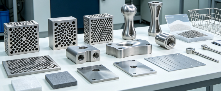
Core Biomechanical Benefits of Hybrid Lattice-Solid Implant Design
The split hybrid geometry separates biological and mechanical performance zones, eliminating the biggest pain points of single-process implants:
- Eliminate stress shielding via graded lattice zones Gyroid/triply periodic minimal surface (TPMS) lattices tune elastic modulus to match human cortical bone (10–30 GPa), avoiding rigid solid titanium that pulls load away from native bone and causes bone resorption over time.
- Maximize bone ingrowth only where needed Porous lattice reserved for bone-contact outer surfaces; solid monolithic core for high-load structural support (hip stem shanks, spinal cage endplates). No wasted porosity on internal non-bone contact geometry.
- Dual surface functionality
- Lattice as-built lightly blasted surface: High micro-roughness for osteoblast adhesion and rapid osseointegration
- 5-axis CNC finished solid surfaces: Ultra-smooth controlled Ra for tight surgical fit, low friction hardware articulation, leak-proof instrument mating
- Custom patient matching without sacrificing precision CT/MRI-derived patient-specific lattice shapes print via SLM; standardized threaded, locking, and instrument interface features finished via repeatable 5-axis CNC for consistent surgical compatibility across custom cases.
- Lower long-term clinical failure risk Hybrid design balances primary surgical fixation (CNC precision threads, flat endplates) and secondary biological fixation (porous lattice bone ingrowth), cutting micromotion under cyclic body load.
Full Regulated Hybrid Manufacturing Workflow
Deviating from this order creates warpage, dimensional shift, biocompatibility risks, or FDA audit non-conformances. All steps run under ISO 13485 medical QMS with full single-unit traceability:
- Patient DICOM CAD Design: Split hybrid geometry (lattice bone-contact zones + solid CNC finish zones)
- Medical Ti6Al4V ELI SLM Powder Bed Printing (inert argon chamber)
- Controlled inert cool-down + automated depowder lattice channel purge
- On-build-plate vacuum stress relief annealing (620°C, 2hr hold)
- Wire EDM separate implant from titanium build plate
- Sacrificial SLM support removal + rough lattice blend deburr
- Pre-HIP XCT CT volumetric screening (filter large unrepairable voids)
- HIP Hot Isostatic Pressing (920°C, 100MPa, 2hr) to close micro-porosity
- Secondary low-temperature beta annealing to refine titanium microstructure
- Single-setup 5-axis cleanroom CNC finishing (threads, endplates, instrument interfaces, datum flats)
- Lattice-only controlled glass bead blasting (mask all CNC machined precision surfaces)
- Multi-stage medical ultrasonic solvent + DI water deep cleaning
- Implant-grade electropolishing / passivation (biocompatible surface treatment)
- Full multi-stage NDT: XCT, DPI dye penetrant, CMM GD&T dimensional inspection
- Laser permanent UDI data matrix marking (MIL‑STD‑130 medical compliant)
- Vacuum bake-out, sterile barrier packaging, batch DHF design history file archive
Lattice SLM 3D Print Design & DFM Rules for Osseointegration
All porous lattice regions follow strict biomaterial and manufacturability rules to guarantee bone ingrowth while simplifying post-print processing:
Lattice Biomechanical Spec Standards (Ortho FDA Accepted)
- Pore size: 500–800μm (optimal for osteoblast penetration and vascularization)
- Strut diameter: 0.3–0.6mm, gradient thickening at solid-lattice transition edges to avoid fracture
- Porosity range: 60–85% for non-load bearing bone contact; 40–60% for partial load zones
- Preferred lattice architecture: Gyroid TPMS (uniform stress distribution vs cubic simple lattices)
SLM Print DFM Rules to Avoid Hybrid Process Failures
- Create clear 1.5mm solid transition buffer zone between lattice and CNC machined regions Buffer absorbs thermal stress during HIP/heat treatment, prevents lattice strut damage during 5-axis fixturing and machining cuts
- Design lattice with self-supporting overhang angles ≥45° to minimize dense internal support structures Hidden support residues trapped in lattice voids cannot be fully removed, causing biocompatibility contamination risks
- Avoid ultra-thin struts <0.25mm; prone to breakage during depowdering and blasting
- Leave uniform 0.1–0.2mm machining stock on all solid CNC finish surfaces post-SLM printing Compensates for HIP uniform volumetric shrinkage and thermal distortion
- Separate all fixture contact datums to fully solid non-lattice geometry; never clamp porous lattice during CNC finishing (strut collapse risk)
5-Axis CNC Finishing Critical Rules for Implant Mating Surfaces
5-axis machining exclusively processes the solid functional zones of hybrid implants, with medical cleanroom dedicated equipment to eliminate particle contamination:
Mandatory Tolerance Targets for Orthopedic Implant Critical Features
- Threaded fixation bores / locking screw interfaces: ±0.003mm positional tolerance, 2B medical thread class fit
- Spinal cage endplate flatness: ≤0.004mm across full contact surface
- Surgical instrument mating tapers: ±0.002mm concentricity
- Non-critical solid outer walls: Relaxed ±0.02mm to cut cycle time and cost
5-Axis Hybrid Implant DFM Best Practices
- Single-setup 5-axis machining only; multiple re-fixturing creates tolerance stack-up on implant mating features
- Short rigid shrink-fit carbide tool holders to eliminate chatter on thin solid transition zones adjacent to lattice
- Program full masking protection for all lattice porous areas during CNC cutting; coolant swarf must not embed into pore structures
- Machine all datum reference flats first post-HIP to correct uniform thermal shrinkage distortion
- Internal threaded holes include micro vent slots to eliminate virtual leaks during implant sterilization cycles
- All machined internal corners minimum R1 fillets to reduce stress risers under cyclic body load
Surface Finish Separation Rule
- CNC machined functional surfaces: Ra ≤0.2μm (electropolished post-machining for low friction, easy sterilization)
- Lattice bone-contact zones: Unmachined, controlled bead blast Ra 3–6μm to boost osteointegration
Separate Process Boundaries: Lattice Zones vs CNC Machined Solid Zones
Clear CAD zoning eliminates cross-contamination, machining damage, and inconsistent clinical performance—enforce these hard design boundaries on all hybrid implant models:
- Bone Ingrowth Lattice Zones (SLM Only, No CNC Cutting)
- Outer implant peripheral surfaces contacting native bone
- Gradient porous architecture, no machining removal of strut/pore geometry
- Post-print processing only: depowder, HIP, bead blast, medical cleaning
- Structural Solid Core Zones (SLM Base Stock + 5-Axis Finish)
- Internal load-bearing monolithic core, instrument connection tapers, locking threads, endplate contact flats
- 0.1–0.2mm uniform machining stock left post-SLM for precision finishing
- All tight GD&T tolerances, thread profiles, surgical mating features machined here
- Transition Buffer Zone (1.5mm Solid Band Between Lattice & Machined Core)
- Acts as mechanical barrier during fixturing, blasting, and machining
- Gradually shifts elastic modulus between porous lattice and dense solid titanium to cut stress concentration at interface Forbidden design mistake: Lattice struts extending directly into threaded bores or flat mating endplates—machining will shear porous struts and create loose titanium micro-debris inside implant pore structures.
HIP & Medical-Grade Post-Processing Sequence for Ti6Al4V ELI
HIP is non-negotiable for load-bearing hybrid orthopedic implants; sequencing is locked to avoid dimensional distortion of CNC finish zones:
- Pre-HIP XCT Screening: Reject parts with large interconnected voids (HIP only closes isolated micro-pores <50μm)
- HIP Cycle: 920°C, 100MPa argon pressure, 2hr hold, slow furnace cool to eliminate SLM internal porosity, boost fatigue strength 2.5x
- Beta Annealing Post-HIP: 780°C hold to remove brittle martensite α’ phase formed during SLM laser melting, improve long-term cyclic load resistance
- Only after full thermal cycles execute 5-axis CNC finishing All heat treatment creates uniform volumetric shrinkage; machining prior to HIP/annealing will push critical mating surface tolerances out of spec permanently.
Mandatory Cleanroom Finishing, Surface Treatments & Biocompatibility Checks
All post-CNC finishing takes place in ISO 7 Class 1000 medical cleanrooms to eliminate foreign body contamination risk for implant patients:
Lattice Zone Exclusive Treatment
- Low-pressure glass bead blasting (mask all CNC machined solid surfaces with medical silicone film)
- Blast media size controlled 40–60μm to avoid embedding particles into lattice pores
CNC Machined Solid Zone Exclusive Treatment
- Medical-grade electropolishing: Dissolves surface micro-peaks, delivers Ra ≤0.1–0.2μm, ultra-low outgassing, resistant to repeated autoclave/ETO sterilization cycles
- Passivation per ASTM A967 to eliminate free iron surface contamination
Universal Multi-Stage Medical Cleaning (All Hybrid Implants)
- Heated ultrasonic medical detergent bath (remove machining coolant, blasting media residues)
- High-purity IPA rinse
- Multiple DI water flushing of internal lattice channels
- 120°C vacuum bake-out 12hr to eliminate residual organic contaminants
Biocompatibility Validation Mandates
Every production batch supplies ISO 10993 test documentation: cytotoxicity, sensitization, irritation, hemolysis, corrosion resistance reports for FDA/MDR submission.
Common Cost & Compliance Mistakes in Hybrid Implant Production
These frequent design/production errors trigger scrap batches, audit findings, or clinical performance failures:
- Machining lattice porous zones directly during 5-axis operations → broken struts, trapped metal micro-debris inside pores
- Skipping transition buffer zone between lattice and solid core → high stress concentration, implant fracture under body load
- Running CNC finishing before HIP/annealing → thermal shrinkage pushes threads/endplates out of tolerance
- Unmasking CNC precision surfaces during bead blasting → rough Ra ruins surgical fit and sterilization performance
- Overly complex fine lattice support structures with no automated depowder access → trapped powder residues failing biocompatibility tests
- Mixed batch Ti6Al4V standard vs ELI powder → inconsistent microstructure, invalid ISO 10993 records
- Missing UDI laser marking on finished implants, or marking located on lattice zones (blasted away during surface treatment)
- Overspecifying ultra-tight tolerances on non-functional solid core areas → extended 5-axis cycle time and higher production cost
Real Case: Patient-Specific Lumbar Spinal Cage Hybrid Lattice + 5-Axis Finish
Project Background
Custom patient lumbar fusion cage, hybrid design: outer gyroid lattice bone-contact walls, solid internal threaded locking core and flat endplates. FDA Class II orthopedic implant requiring full ISO 13485 traceability and MDR technical file documentation.
Original Unoptimized Design Flaws
- No 1.5mm transition buffer between lattice and solid core, predicted high stress concentration at interface
- Lattice struts extended into threaded bores, risk of strut shear during CNC tapping
- All surfaces unmasked during blasting, ruining flat endplate sealing surface roughness
- CNC machining scheduled pre-HIP, projected 0.04mm shrinkage tolerance drift on mating endplates
Implemented Hybrid Design & Workflow Fixes
- Added full 1.5mm solid transition band separating lattice porous walls and solid machined core
- Redrew CAD to fully contain all threads, endplates, instrument tapers within solid non-lattice geometry
- Standardized silicone masking SOP for all CNC finished surfaces pre-blasting
- Reordered workflow: SLM print → stress relief → HIP/annealing → 5-axis cleanroom CNC finishing
- Optimized lattice strut thickness to 0.45mm with 65% porosity for balanced bone ingrowth and structural strength
Measurable Clinical & Production Outcomes
- CMM inspection confirmed all critical endplate flatness ≤0.0038mm, thread positional tolerance ±0.003mm
- XCT post-processing verified full lattice pore clearance, zero trapped powder residues
- Passed full ISO 10993 biocompatibility and cyclic fatigue testing
- Single-setup 5-axis workflow cut CNC cycle time by 42% vs original multi-fixture program
- Successfully passed FDA pre-market audit with complete unbroken batch traceability records
FAQ
Why can’t we fully machine porous lattice structures with 5-axis CNC instead of SLM printing?
CNC cannot manufacture interconnected gradient gyroid/TPMS porous lattices with controlled 500–800μm uniform pores. Milling only creates open cutouts, not continuous biomimetic bone-matching porous architecture required for osseointegration. SLM delivers the biological lattice geometry; 5-axis fixes the mechanical precision limitations of as-printed solid surfaces.
Is HIP mandatory for all hybrid lattice bone implants?
Yes for load-bearing spinal, hip, trauma implants. HIP closes SLM micro-porosity that would act as fatigue crack initiation points under cyclic body load. Low-load non-structural dental implant abutments may waive HIP only with formal engineering risk file approval per ISO 14971.
Can I machine lattice zones with 5-axis to smooth strut surfaces for better bone ingrowth?
Never machine lattice porous zones. Cutting struts creates sharp micro-fractures and loose titanium particles trapped inside pores, triggering inflammatory foreign body reactions in patients. Controlled bead blasting is the only approved surface treatment for lattice bone-contact areas.
What tolerance can 5-axis cleanroom CNC hold on hybrid implant threaded mating surfaces?
Medical dedicated 5-axis machines in Class 1000 cleanrooms consistently deliver ±0.002–±0.003mm positional tolerance for implant threads and instrument tapers, flatness ≤0.004mm on load-bearing endplates—far tighter than as-built SLM ±0.1–0.2mm baseline dimensional drift.
How do I maintain full FDA/ISO 13485 traceability for hybrid SLM + CNC implant batches?
Every single implant unit carries a permanent UDI data matrix laser mark encoding SLM powder heat lot, HIP batch ID, CNC work order number, heat treatment log serial number, and finishing batch record. All DHF device history files cross-reference each process stage with operator, machine, and test result records retained minimum 10 years for orthopedic implants.
What’s the optimal transition buffer width between lattice and solid machined zones?
Industry validated minimum 1.5mm solid titanium buffer band. This eliminates strut fracture risk during fixturing/machining, balances elastic modulus gradient, and prevents blasting media from contaminating machined precision surfaces.
Why must all 5-axis CNC finishing happen after HIP and heat treatment?
HIP and beta annealing create uniform volumetric shrinkage across the entire hybrid implant body. If tight tolerance threads/endplates are machined pre-thermal processing, shrinkage shifts dimensions out of clinical spec with no corrective rework option.
What surface roughness targets separate lattice vs CNC machined implant zones?
Lattice bone ingrowth zones: Ra 3–6μm (controlled bead blast only). CNC machined surgical mating/threaded zones: Ra ≤0.2μm post-electropolish for smooth, easy sterilizable instrument fit and minimal friction.
Can hybrid SLM + 5-axis workflow support patient-specific custom orthopedic implants?
Perfectly suited for custom patient cases. DICOM CT scans generate unique lattice outer bone-contact geometry printed via SLM, while standardized threaded, locking, instrument interface features follow repeatable 5-axis CNC programs for consistent surgical compatibility across all custom patient implants.
What cleanroom class is required for 5-axis finishing of hybrid bone implants?
ISO 7 Class 1000 dedicated medical cleanroom for all CNC cutting, deburr, and pre-finish operations. Separates implant manufacturing from general workshop contamination to satisfy ISO 10993 biocompatibility and FDA foreign body risk controls.
Quick Hybrid Implant Design & Production Compliance Checklist
Lattice SLM Design Checklist
Gyroid TPMS lattice 500–800μm pore size, 60–85% porosity bone contact zones
1.5mm solid transition buffer band separates lattice and CNC machined core
All lattice struts ≥0.3mm minimum thickness, self-supporting ≥45° overhangs
No porous lattice extending into threaded bores, endplates or instrument tapers
Uniform 0.1–0.2mm machining stock left on all solid functional surfaces
5-Axis CNC Finishing Compliance Checklist
All critical mating features machined single-setup 5-axis to eliminate tolerance stack-up
Silicone masking fully covers all lattice porous zones pre-machining / blasting
Threads, endplates, tapers held ±0.003mm positional / flatness GD&T tolerance
CNC operations executed only after full HIP + beta annealing thermal cycles
Short rigid tool holders used to eliminate chatter adjacent to lattice transition zones
Regulatory Post-Processing & Traceability Checklist
Ti6Al4V ELI medical grade powder with full MTR heat lot traceability
Pre-HIP XCT volumetric screening documented for every implant batch
All finished implants laser marked with UDI data matrix per FDA/MIL‑STD‑130
Separate bead blast (lattice only) + electropolish (CNC solid zones) surface treatment
Full ISO 10993 biocompatibility, NDT, CMM records archived in DHF device history file
Closing Wrap-Up
Hybrid lattice SLM 3D print paired with precision 5-axis cleanroom CNC finishing solves the two biggest limitations of single-process bone implant manufacturing: biomimetic porous bone ingrowth geometry and clinical-grade ultra-tight surgical mating precision.
By splitting implant design into dedicated lattice biological zones and solid machined mechanical zones, following the fixed thermal-then-machining workflow, and enforcing strict cleanroom/biocompatibility standards, orthopedic OEMs produce implants that deliver faster osseointegration, superior long-term fatigue performance, and full FDA/MDR regulatory audit compliance.
Critical design mistakes like unbuffered lattice-solid transitions, premature CNC machining before HIP, and unmasked porous surfaces create costly scrap batches and clinical risk. Applying the DFM rules and sequenced production workflow in this guide eliminates these failures while streamlining custom patient-specific and standard implant manufacturing.
If you require a hybrid implant DFM design review for your spinal, hip, or trauma bone implant CAD files, share your STEP geometry and clinical performance specs for a free lattice-solid zoning optimization and process cost breakdown aligned with ISO 13485 medical manufacturing standards.


