
Published:Zorapid.Ltd
Engineers often design CNC parts around ideal simulation performance, not real-world manufacturing limits or actual functional requirements. Common missteps: global ultra-tight tolerances, exotic alloys, excessive freeform geometry, unnecessary micro-features, oversized monolithic blocks, and redundant fatigue/finishing specs applied to non-critical areas.
These choices drastically increase 5-axis cycle times, require slow finishing passes, raise scrap rates, add expensive special processes, inflate raw material waste, and extend lead times—while delivering little to no tangible performance benefit.
Over-engineering ≠ better quality; it is unnecessary cost and risk. The goal is to apply strict specs only where functionally required, and use proven DFM rules for the rest of the part. This guide provides actionable steps to rationalize specs, simplify geometry, and cut CNC costs while preserving critical performance, safety, and compliance requirements.
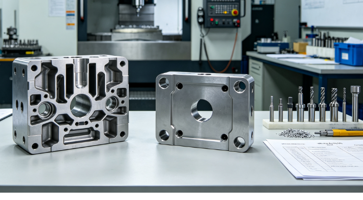
Core Forms of CNC Over-Engineering & Their Hidden Costs
1. Global blanket tight tolerances
Applying micron-level GD&T tolerances (e.g., ±0.005mm) across the entire part, rather than only mating, sealing, threaded, or fatigue-critical zones.
- Hidden cost: 2–3x longer finishing cycles, constant CMM inspection, higher scrap rates, slower feed rates, expensive 5-axis runtime
- Root cause: Copy-paste drawing templates, simulation-only design, lack of tolerance analysis
2. Excessive complex geometry & arbitrary micro-features
Random unique radii, countless blind micro-holes, ultra-deep narrow pockets, unnecessary freeform contours, unneeded compound angles, non-functional thin lattices.
- Hidden cost: chatter, tool breakage, constant tool changes, extra CAM programming time, custom fixturing, poor repeatability
- Root cause: aesthetic design, direct 3D simulation export without DFM validation
3. Over-specified premium materials & special processes
Specifying medical PEEK, Ti, 316L VIM-VAR, full electropolishing, HIP, 100% CMM inspection, or aerospace shot peening for non-load-bearing, non-regulated, non-fluid-contact regions.
- Hidden cost: 3–10x higher raw material cost, longer cycle times, expensive NADCAP/cleanroom processing, extended lead times
- Root cause: one-size-fits-all material specs, risk-averse blanket specs, no zone-based surface treatment rules
4. Poor monolithic over-consolidation
Merging many modular, serviceable subassemblies into one giant 5-axis monolithic billet with no modularity.
- Hidden cost: massive billet waste, extremely long 5-axis cycles, total scrap risk if one feature fails, impossible field repair, high rework cost
- Note: Smart targeted consolidation is good; full blind monolithic merging is over-engineering
5. Excessive safety margins & redundant features
Extra thick walls, redundant bolt holes, duplicate fastener patterns, arbitrary heavy fillets, unvalidated extra stiffeners added purely for simulation safety.
- Hidden cost: excess material removal time, higher residual stress distortion, increased weight, longer roughing cycles
6. Prototype geometry directly reused for mass production
NPI-specific complex support geometry, custom test features, and ultra-fine prototype details carried forward unchanged to high-volume production.
- Hidden cost: perpetual prototype pricing, slow cycle times, unoptimized tool paths
7. Over-spec surface finish requirements
Mirror Ra specs for hidden internal non-contact surfaces, full cosmetic finish across the entire part, unnecessary full passivation/anodizing on non-exposed zones.
- Hidden cost: extra finishing cycles, manual polishing, batch inspection delays, higher per-unit cost
Structured Tolerance Rationalization
Step 1: Create Zone-Based GD&T Drawings
- Critical Zones (Controlled Tight Specs): Mating flanges, sealing surfaces, threaded bores, bearing interfaces, fatigue paths, regulatory/airworthiness features
- Keep validated tight GD&T tolerances (e.g., ±0.003mm for vacuum flanges, medical mating features)
- General Zones (Relaxed Standard Specs): Non-mating outer shells, internal non-load pockets, cosmetic non-critical surfaces
- Use standard CNC baseline tolerances: ±0.05mm linear, ±0.3° bend/angular tolerances, standard Ra values (Ra 1.6–3.2μm)
- Use GD&T datum referencing strictly to primary functional datums, avoid redundant datum calls
Step 2: Perform Formal Tolerance Stack-Up Analysis
- Use tolerance stack-up / Monte Carlo simulation to confirm relaxed tolerances do not impact assembly fit, function, or fatigue life
- Avoid hard-coding global tolerance in drawing templates; use CAD layer/color coding to mark critical zones clearly
- Document all tolerance changes with engineering change orders (ECOs) and FMEA updates for regulated (IATF16949/AS9100/ISO13485) products
Step 3: Validate with First Article (FAI)
- Run FAI/AS9102 validation after tolerance rationalization; confirm assembly fit, leak, and durability performance are unchanged
- Implement SPC monitoring on only critical GD&T features, not all dimensions, to reduce QA inspection time
DFM Feature Simplification & Standardization
1. Standardize Geometry
- Use consistent radii (e.g., R3 / R5), standard hole sizes, fastener sizes, fillet rules across the full BOM
- Eliminate one-off unique radii, odd hole sizes, custom thread profiles where standard thread specs work
- Reduce tool change count by consolidating feature sizes to a minimal tool set; reduce idle spindle time
2. Simplify Deep/Thin Features
- Eliminate unnecessary ultra-thin non-structural walls, validate minimum wall thickness via simulation + physical testing
- Add uniform fillets to reduce stress risers without arbitrary over-sizing; avoid extremely deep narrow slots (chatter risk, slow feeds)
- Add uniform transition geometry to reduce residual stress and eliminate slow micro-finishing cycles
3. Minimize Unnecessary 5-Axis Contours
- Use indexed 5-axis for fixed-angle holes/bosses instead of continuous simultaneous 5-axis where possible
- Eliminate freeform sculpting on non-aesthetic/non-performance surfaces; revert to prismatic geometry (3-axis machinable)
- Reduce total rotary axis travel by grouping similar-angle features to cut idle rapid movement time
4. Add DFM Draft & Relief Features
- Apply standard bend radii, bend relief notches, and standard draft angles for milled/extruded geometry
- Remove hidden undercuts requiring expensive custom slides/lifters/fixtures where functionally feasible
Material & Surface Treatment Spec Rationalization
1. Zone-Based Material Specification
- Use premium alloys (Ti, PEEK, 316L VIM-VAR) only in high-load, corrosive, vacuum, or regulatory critical regions
- Use standard grades (6061-T6, 7075, 304L, carbon steel) for general structural regions where validated by simulation and durability testing
- Avoid blanket full-billet premium material; consider bonded hybrid assemblies (standard base + premium inserts) where appropriate
- Validate raw material MTR compliance only for regulated critical zones
2. Targeted Surface Finishing
- Apply electropolish, hard anodize, passivation, vacuum bake, and HIP only to specified critical zones; mask non-critical surfaces
- Use baseline bead blast / standard anodize for general surfaces; avoid full mirror finishing unless required for fluid flow/fatigue performance
- Document masking SOPs and validate coating thickness to avoid assembly interference
- Reserve cleanroom processing only for regulated medical/semiconductor contact zones
3. Residual Stress & Heat Treatment Rules
- Apply formal stress relief / HIP cycles only for fatigue-critical load-bearing components; skip costly full-batch thermal processing for static non-critical brackets
- Schedule thermal processing before final precision finishing to avoid rework, and align with formal NADCAP/AMS specs when required
Balanced Part Consolidation (Avoid Bad Monolithic Designs)
Good Consolidation
- Merge multiple small fastener-heavy simple brackets into a single repeatable prismatic assembly to reduce fixturing and assembly labor
- Reduce leak paths and fastener count for fluid manifolds using moderate integrated geometry, while maintaining modular serviceable segments
- Use hybrid designs: standard prismatic base + precision mill-turn/5-axis critical inserts (balance cost + precision)
Bad Over-Engineering Consolidation
- Full single huge monolithic billet replacing modular serviceable assemblies
- Merging dissimilar thermal/load regions into a single large 5-axis block with no modularity
- Excessively deep pocketing removing 70%+ of billet material (massive waste + residual stress risk)
Rule of Thumb
- Consolidate when it reduces total assembly cost without increasing core raw billet cost or eliminating field replaceability
- Always perform total landed cost analysis (material + machining + inspection + assembly + warranty) before monolithic redesign
Separate NPI Prototype vs Mass Production CAD
1. Maintain Two Formal Drawing Revisions
- NPI/Prototype CAD: Full complex geometry, test features, ultra-tight validation specs, for validation and fatigue testing
- Mass Production CAD: DFM optimized, rationalized tolerances, standardized features, removed prototype test geometry, validated via FAI
- Use formal ECO/PLM change control (e.g., Siemens PLM, PTC Windchill) to prevent accidental prototype geometry production runs
2. Iterate via Simulation + Physical Validation
- Validate performance via FEA + physical durability/leak/fatigue testing, not purely simulation results
- Reduce prototype batch size to limit cost exposure while completing DFM and tolerance validation
- Create a formal DFM baseline drawing locked for mass production, controlled by QA/engineering sign-off
Cross-Functional DFM Review Process
Form a DFM Review Team
Include: design engineer, manufacturing/CNC programmer, quality engineer, procurement, and supplier senior engineers (for Asian/global CNC suppliers)
- Hold DFM reviews early (pre-steel/pre-machining release), not after final drawing lock
- Run formal FMEA (DFMEA/PFMEA) to identify risk vs cost trade-offs
- Use formal DFM checklists (included below) in every design gate review
Cost Target Design (Target Costing)
- Define total landed cost targets upfront, then iterate CAD geometry to hit targets
- Request formal line-item CNC cost breakdowns from suppliers (material, setup, runtime, inspection, secondary processes)
- Run quarterly DFM cost reviews with key CNC suppliers for continuous improvement
Supplier DFM Feedback
- Share functional requirements, not just fixed CAD geometry; invite supplier CAM/DFM engineers to suggest geometry simplifications
- Structure win-win DFM cost-sharing agreements (e.g., split DFM savings) to encourage supplier optimization
Common Pitfalls & How to Avoid Them
- Pitfall 1: Over-Relaxing Critical Specs
- Risk: assembly misfit, fatigue failure, leakage, regulatory non-compliance, warranty failures
- Fix: formal FMEA, tolerance stack-up analysis, FAI validation, SPC monitoring of critical GD&T features
- Pitfall 2: Removing Required Validation/Processes
- Risk: hidden residual stress, fatigue failure, corrosion, medical/aero audit non-conformance
- Fix: retain formal regulated special processes (NADCAP, ISO 13485) for regulated zones only, not entire parts
- Pitfall 3: Blunt Massive Percentage Discount Negotiation Instead of DFM Optimization
- Risk: supplier secretly cutting critical process steps (inspection, finishing, tool quality) to hit price targets
- Fix: baseline DFM cost model + line-item quoting, formal SLA quality agreements
- Pitfall 4: Inadequate Change Control
- Risk: mixed CAD revisions, non-compliant production batches
- Fix: PLM controlled ECOs, formal FAI validation after every major revision
- Pitfall 5: Excessive Pure Simulation-Based Design
- Risk: unrealistic geometry, unvalidated safety margins
- Fix: physical prototype durability testing + SPC process validation
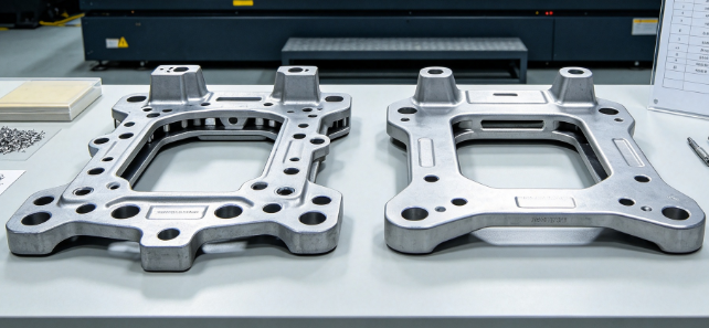
Real-World Case Study: EV Chassis Bracket Cost Reduction
Original Over-Engineered Design
- Full 5-axis monolithic 7075 aluminum bracket, global ±0.02mm tolerance, unnecessary freeform sculpting, full hard anodize, 100% CMM inspection
- Cycle time: 92 mins / pc, scrap rate: 7%, monthly 2,000 unit volume, high 5-axis machine cost
DFM Rationalization Changes
- Zone GD&T: only mounting holes/datum faces at ±0.02mm, general surfaces relaxed to ±0.05mm
- Remove non-functional freeform sculpting, convert to prismatic 3-axis machinable geometry
- Standardize fillets, hole sizes, remove redundant stiffener geometry validated unnecessary via FEA + vibration testing
- Apply hard anodize only to mating datum zones, baseline clear anodize for general surfaces
- Reduce 100% CMM inspection to critical feature sampling SPC inspection
Results
- Cycle time reduced to 47 mins (49% reduction)
- Scrap rate <0.5%, validated durability/NVH performance unchanged
- Total per-unit cost reduced 38%, annual manufacturing cost savings >$220k
- Passed IATF 16949 validation and full vehicle durability testing
FAQ
What is the #1 root cause of CNC over-engineering cost waste?
Global blanket ultra-tight tolerances applied to non-critical geometry, forcing slow finishing cycles and full-batch precision inspection, with no functional justification. Zone-based GD&T rationalization is the fastest cost reduction lever.
How can I validate that DFM simplification won’t hurt product performance?
Formal tolerance stack-up analysis, FEA simulation, accelerated durability/vibration/leakage testing, formal FMEA risk review, and FAI first article validation + SPC critical feature monitoring. Never relax critical safety/regulatory specs.
When is a full monolithic 5-axis CNC design appropriate?
Primarily for regulated fluid manifolds, high-cycle fatigue aero components where leak paths/micro-motion must be eliminated, with formal FEA/fatigue validation. Avoid general structural mass-production monolithic designs unless validated for total landed cost benefit.
How do I handle regulated aerospace/medical parts and avoid over-engineering?
Apply full regulatory specs (NADCAP, ISO 13485, AS9100) only to defined critical traceability/functional zones, and use standard DFM rules for non-critical geometry, documented via DHF/DFMEA records and formal ECO change control.
Should I always use 3-axis instead of 5-axis to cut cost?
Use 5-axis only for validated complex critical contours and tight GD&T mating surfaces; revert to 3-axis/prismatic geometry for non-critical regions to reduce expensive 5-axis runtime.
How do I communicate DFM changes to global Asian CNC suppliers?
Use annotated 2D drawings + STEP files with color-coded critical zones, formal ECO revisions, line-item quotes, FAI validation, and bilingual written agreements, not verbal changes.
What is the difference between DFM optimization and over-simplification?
DFM optimization preserves validated critical function, fatigue, safety, regulatory specs, while simplifying non-critical geometry. Over-simplification removes validated critical features or tolerances, creating functional risk.
How do I calculate the cost impact of over-engineering?
Create a baseline CNC cost model (material + setup + runtime + inspection + secondary processes) and compare baseline vs DFM-rationalized geometry cost; include scrap, rework, and warranty risk costs in total landed cost analysis.
Can DFM rationalization reduce CNC lead time?
Yes, significantly: reduced 5-axis cycle time, simplified CAM programming, reduced inspection time, fewer special processes, and faster validation, cutting overall lead times by weeks in complex regulated programs.
How often should I review and rationalize CNC part drawings?
Quarterly BOM cost reviews, formal DFM reviews during major product revisions, and annual mass-production baseline DFM validation; always conduct DFM reviews before new annual volume framework pricing agreements.
Quick Over-Engineering DFM Checklist
Tolerance & GD&T Review
Color-coded critical/non-critical GD&T zones defined, validated via tolerance stack-up analysis
Non-critical features set to standard baseline CNC tolerances (±0.05mm linear)
Formal ECO/PLM change control for all tolerance revisions
SPC monitoring limited only to validated critical GD&T features
Geometry DFM Review
Standardized radii, hole sizes, fastener specs across the part
Removed unnecessary freeform contours, micro blind holes, extreme thin non-structural walls
Validated wall thickness and fillet geometry via FEA + physical testing
Minimized continuous 5-axis simultaneous machining for non-critical surfaces
Avoided blind full monolithic consolidation (unless formally validated)
Material & Surface Spec Review
Premium alloys/special processes (HIP, electropolish, cleanroom) limited to validated critical zones
Non-critical surfaces use baseline standard finishing and commodity alloys
Formal masking SOP for targeted coating/finishing
Regulated special processes documented and validated (NADCAP/ISO)
NPI / Mass Production Drawing Control
Separate validated mass-production DFM CAD vs NPI prototype CAD
Prototype test features removed from mass-production drawings
FAI validation complete after DFM revisions
Full BOM DFM review scheduled quarterly
Supplier & Cost Validation
Formal line-item CNC quote breakdown requested from suppliers
DFM win-win cost reduction process established with key suppliers
Full total landed cost analysis (including scrap/inspection/ freight)
Formal SLA quality agreements in place for regulated production batches
Closing Wrap-Up
Over-engineering is a pervasive hidden cost driver across CNC manufacturing—caused by blanket specs, simulation-only design, prototype geometry carryover, and risk-averse one-size-fits-all specs. The core fix is zone-based specification management + cross-functional DFM validation: protect the critical few, simplify the rest.
When executed correctly, structured DFM rationalization can cut CNC landed costs by 30–40% while maintaining validated core performance, regulatory compliance, and fatigue durability. The key guardrail is formal FMEA, tolerance stack-up analysis, FAI validation, and PLM change control to avoid unsafe over-simplification.
If you want a quick DFM review of your CNC part CAD, share the STEP file and functional specs, and I can flag over-engineered zones and provide a targeted cost-reduction plan.


