
Published:Zorapid.Ltd
Complex integrated workpieces combine rotational axis features (shafts, threads, tapers, bearing races) + prismatic/freeform features (keyways, flats, angled holes, 3D contours, cooling channels, lugs, manifolds). Traditional separate lathe + 3/5-axis milling requires repeated re-fixturing, creating massive tolerance stack-up, wasted cycle time, and poor repeatability—especially for tight GD&T concentricity, runout, and angular position specs.
Hybrid Mill-Turn (Multi-Tasking CNC) machines combine full turning spindles + live milling spindles, C/Y/B rotary axes, and often sub-spindles for single-setup complete machining. They eliminate re-fixturing errors, reduce cycle times, improve runout precision, and enable monolithic integrated part designs for aerospace, medical, energy, and automotive high-performance components.
This guide covers hybrid mill-turn machine setups, DFM rules, programming workflows, chatter control, validation, and regulated compliance best practices for complex integrated workpieces.
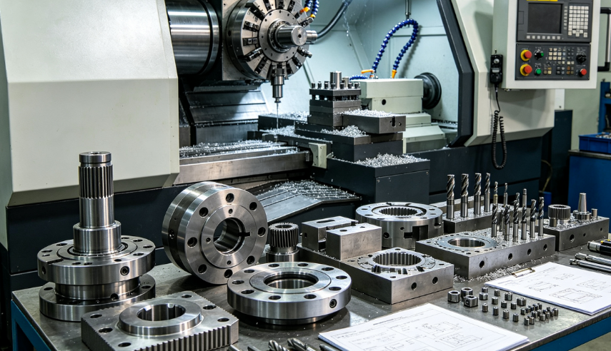
Key Hybrid Mill-Turn Machine Architecture
Main Types
- Horizontal Mill-Turn Multi-Tasking Centers
- Main spindle + B-axis (swiveling milling head), C-axis spindle indexing, Y-axis cross travel, sub-spindle for backside finishing
- Full turning + 5-axis simultaneous milling, deep hole drilling, thread whirling, and complex contouring
- Ideal for large aerospace shafts, turbine shafts, oil & gas valve bodies, gear shaft assemblies
- Swiss-Type Mill-Turn Lathes (Sliding Headstock)
- Guide bushing support for ultra-thin long slender parts, multiple live tool stations, C-axis, gang tooling
- High precision, tight tolerance small complex medical implants, dental abutments, fuel injector pins, micro valve components
- Excellent for high aspect ratio slender integrated parts prone to deflection/chatter
- Vertical Mill-Turn Centers
- Vertical main spindle + live tooling, rotary tables; suited for large flanged integrated housings, wheel hubs, chuck-style heavy workpieces
Core Capabilities
- C-axis: Full spindle indexing + continuous contour milling on rotational surfaces
- Y-axis: Off-center milling, keyways, cross holes, flat features (critical for non-radial prismatic geometry)
- B-axis: Swivel milling head for 5-axis angled holes and freeform contours
- Sub-spindle: automatic part handoff for backside milling/turning, complete 2-sided machining in one setup
- Live tool stations: driven carbide tools for drilling, tapping, milling, thread whirling
- Bar feeders / bar pullers: automated continuous production for bar stock blanks
Primary Benefits
- Eliminate re-fixturing tolerance stack-up: maintain ultra-tight runout, concentricity, and angular datum accuracy
- Reduce total cycle time drastically (single setup, reduced idle transport/probing time)
- Minimize residual stress distortion from repeated clamping
- Enable monolithic integrated part designs (reduce multi-part assembly, fasteners, leak paths)
- Improve surface finish and fatigue performance via continuous low-distortion machining
- Reduce WIP inventory, fixturing costs, and human handling error
Common Complex Integrated Workpiece Applications
- Aerospace & Energy:
- Integrated turbine shafts, fuel manifold fittings, hydraulic valve spools, landing gear pin assemblies, engine compressor blisk hubs
- Key specs: tight runout, high fatigue life, low leakage, full material traceability (AS9100/NADCAP)
- Medical Implants & Surgical Hardware:
- Titanium hip stem tapers, spinal screw bodies, dental abutments, bone fixation screws with multi-lobed geometry
- Key specs: biocompatible Ti6Al4V ELI, precise thread profiles, controlled surface roughness, ISO 13485 compliance
- Automotive & Motorsport:
- Integrated gear shafts, turbo valve shafts, axle spindle assemblies, fuel injector bodies, hybrid e-motor rotor shafts
- Key specs: NVH control, high cyclic fatigue, IATF 16949 repeatability
- Semiconductor & Precision Instrumentation:
- Vacuum feedthrough shafts, metering valve spindles, precision spindle assemblies, optical lens mounts
- Key specs: ultra-low runout, low-outgassing finishes, micron tolerances, consistent surface finish
Core DFM Design Rules for Hybrid Mill-Turn Parts
The biggest mill-turn cost/scrap risk comes from poor CAD geometry that creates chatter, collision risk, or requires unnecessary slow cycles:
- Establish a unified main spindle datum
- All GD&T datums referenced to the primary spindle axis (A-axis), not secondary arbitrary datums
- Specify concentricity, total runout, and angular position tolerances relative to the main rotational axis
- Avoid over-specifying ultra-tight tolerances on non-critical prismatic features to reduce cycle time
- Balance part mass for high-speed turning
- Avoid extreme asymmetric lugs/features that create unbalanced centrifugal load at high spindle RPM (risk of vibration, spindle damage, poor surface finish)
- Add symmetric balancing geometry or specify low RPM milling cycles for highly asymmetric regions
- Control Wall Thickness & Slender Ratios
- Long slender shafts: follow L/D ratio guidelines (swiss: L/D < 20 with guide bushing; general mill-turn: L/D < 10 unless with steady rest support)
- Add internal gundrilled support cores or external steady rests for deep slender sections to suppress chatter
- Use consistent radii transitions between turned and milled features to reduce stress risers and tool shock loading
- Simplify deep cross-hole / angular hole geometry
- Group similar-angle features to minimize B-axis swivel travel and idle rotary movement
- Avoid tiny deep micro-holes requiring ultra-slow micro-drilling where functionally possible
- Thread whirling preferred over single-point threading for complex multi-lobed medical threads
- Account for post-processing allowance
- Leave controlled stock for final finishing, passivation, electropolish, or heat treatment (HIP/stress relief) if required
- Define masking zones for coating/finishing to protect critical turned sealing surfaces
- Document material & bar stock specs
- Specify bar material (Ti6Al4V, Inconel, 316L, 4340 alloy steel), pre-stress-relieved blanks, bar straightness tolerances upfront
Step-by-Step Mill-Turn Programming & Workflow Best Practices
1: Raw Material Prep & Machine Setup
- Use pre-stress-relieved bar stock, validate bar straightness and runout via spindle dial indicator
- Install steady rests, tailstocks, or guide bushings (swiss mill-turn) for slender workpieces; calibrate sub-spindle alignment, C/Y/B axis kinematics, and thermal compensation
- Set machine ambient temperature control (±1°C) for micron tolerance workpieces; run warm-up cycles to stabilize spindle thermal drift
- Create a unified machine coordinate system (G54) tied to main spindle datum; perform automated probing cycles for bar end face and OD reference
2: Program Sequencing (Critical Order)
- Rough Turning Cycles: Remove majority of rotational stock first (G71/G72/G73), balanced roughing passes to reduce residual stress, moderate depth of cut
- Use constant surface speed (CSS, G96) for turning; adjust RPM automatically for variable diameters
- Rough Milling / Cross Drilling: Prismatic/angled features after primary rough turning, avoid heavy milling cuts on thin walled shaft sections
- Use trochoidal milling for deep pockets/slots to reduce radial tool load and chatter
- Intermediate Stress Relief (if required): For large high-alloy/integrated aerospace workpieces; off-machine vacuum stress relief then re-probe datum
- Finish Turning + Finish Milling: Light depth-of-pass finishing cycles, constant chip load, optimized feed rates
- Use C-axis indexed mode for fixed-angle holes; simultaneous C/B/Y 5-axis mode only for freeform contour surfaces
- Sub-Spindle Hand-off & Backside Machining: Transfer part to sub-spindle for reverse-side features, maintain datum alignment, avoid re-clamping distortion
- Thread Whirling / Finishing Threads: Dedicated thread whirling cycles for complex medical/taper threads, validate pitch/lead with thread gauges
- Deburr & Break Edges: In-program micro-deburr cycles to eliminate sharp micro-notches (fatigue risk)
- In-Process Metrology: On-machine probing cycles to verify runout, concentricity, keyway position, and surface roughness
- Part Unload & Batch Traceability Marking: Laser data matrix marking (MIL-STD-130 / UDI) on non-critical zones for regulated parts
3: CAM Programming Rules
- Use dedicated mill-turn CAM software (Mastercam, Esprit, NX, SolidCAM) with mill-turn post-processors validated for the specific machine controller (FANUC, Mazatrol, Siemens)
- Enable collision simulation (full machine model simulation including B-axis, sub-spindle, tool turret, steady rests) to eliminate catastrophic crashes
- Minimize rapid rotary travel (C/B axis); reorder tool paths to group same-angle features together to reduce axis jerking and idle time
- Reduce tool change count: use multi-functional tools, combined drill/tap tools, and modular live tool holders
- Use feedrate override learning / adaptive control to maintain consistent chip load and prevent chatter
Tooling, Fixturing & Chatter Control Strategies
Tooling
- Turning Tools: Coated carbide ISO inserts (TiAlN/AlTiN), positive rake geometries for low cutting force, chip breakers optimized for alloy/titanium materials
- Use boring bars with vibration-damped (silent bar) tooling for deep internal turning operations
- Live Milling Tools: Short, rigid shrink-fit / hydraulic tool holders, fine-grain solid carbide end mills, high helix, variable pitch flutes for chatter suppression
- Thread whirling inserts for precision medical/taper thread profiles
- High-pressure coolant through-tool (70+ bar) for titanium/Inconel heat control and chip evacuation
- Tool Balancing: Balance high-speed live tools to reduce spindle vibration and extend tool life
- Tool Monitoring: In-process tool wear monitoring (vibration/acoustic sensors, spindle load monitoring) to prevent sudden tool failure and scrap
Fixturing & Support
- Main Spindle Chuck: High-precision hydraulic / collet chucks (not standard jaw chucks) to minimize runout and clamping distortion; soft jaws machined to match part OD profile
- Steady Rests / Tailstocks / Guide Bushings: Mandatory for slender shafts; programmable servo steady rests with adaptive force control to avoid part deflection
- Swiss machines: precision guide bushings for ultra-long micro shafts
- Sub-Spindle Chucking: matched collet/chuck geometry, controlled gripping force to avoid thin-wall crushing
- Vibration Damping: Tuned mass dampers, passive vibration absorbers, low-vibration machine bases, stiff fixturing plates
Chatter Control Core Rules
- Reduce spindle RPM to avoid natural frequency resonance; use spindle speed variation (SSV) cycles
- Reduce radial depth of cut in milling cycles, increase feed per tooth, use variable pitch fluted end mills
- Add temporary sacrificial support ribs for ultra-thin walled integrated sections, remove in final light passes
- Use adaptive milling cycles to maintain consistent chip load
Material-Specific Cutting Parameters & Process Tuning
Ti6Al4V ELI (Medical/Aero Integrated Shafts)
- Turning: CSS ~30 m/min, moderate feed, high-pressure coolant flood cooling; avoid dry cutting to prevent alpha-case formation
- Live Milling: Trochoidal cycles, reduced RPM, variable pitch carbide mills, avoid aggressive side milling
- Post-processing: HIP/beta annealing per AMS specs (if fatigue critical), electropolish passivation, biocompatibility validation (ISO 10993)
Inconel 718 / High-Temp Alloys (Energy/Aero Turbine Shafts)
- Turning: Low constant surface speed, heavy coolant, ceramic/coated carbide inserts; frequent tool monitoring for wear
- Milling: Climb milling, trochoidal roughing, limit radial engagement, reduce chatter risk
- Post-processing: NADCAP heat treatment, controlled shot peening for fatigue life
4340 / Hardened Alloy Steel (Motorsport / Gear Shafts)
- Hard turning with CBN inserts for finish bearing race surfaces; replace grinding where feasible
- Live tool milling for splines/keyways, controlled residual stress
- SPC monitoring for runout and hardness consistency
316L Stainless (Valve Spools, Semiconductor Feedthroughs)
- Low feed turning to minimize built-up edge (BUE), polished inserts, synthetic coolant
- Low-outgassing finishing (electropolish, vacuum bake) for vacuum applications
Metrology, Traceability & Precision Validation
Key GD&T Validation
- Total Runout, Concentricity, Cylindricity: CMM, roundness tester, dial gauge, form measuring machines
- Angular keyway/hole position: CMM 3D GD&T inspection, optical comparators
- Surface Roughness (Ra/Rz): Profilometer for sealing, fatigue, and implant surfaces
- Thread profile validation: thread gauges, 3D scanner inspection
- On-machine probing cycles for real-time drift correction (thermal drift, tool wear drift)
Compliance & Traceability
- AS9100 / ISO 13485 / IATF 16949 full batch travelers: raw MTR heat lots, machine logs, tool change logs, heat treatment logs, CMM reports
- Permanent UDI/data matrix laser marking on non-rotating non-fatigue surfaces (avoid marking main load paths to create stress risers)
- First Article Inspection (FAI / AS9102) for regulated aerospace/medical mill-turn components
- SPC statistical process control for critical runout and concentricity features
Common Mill-Turn Machining Defects & Troubleshooting
- Excessive Runout / Concentricity Error
- Causes: chuck runout, bar straightness, spindle thermal drift, sub-spindle misalignment, unbalanced part, chatter
- Fix: re-calibrate chucks/sub-spindle, run thermal compensation, steady rest support, balance part, validate spindle alignment
- Chatter Vibration & Poor Surface Finish
- Causes: long tool overhang, wrong RPM resonance, inadequate steady rest support, rigidty issues, constant radial milling load
- Fix: variable pitch tools, SSV spindle speed variation, trochoidal milling, add steady rest, shorten tool overhang
- Residual Stress Distortion (Post-Machining Drift)
- Causes: aggressive roughing passes, unrelieved bar stock stress, uneven cutting heat
- Fix: staged roughing + intermediate stress relief, light finish passes, low-heat milling cycles
- Thread Profile Error / Pitch Deviation
- Causes: C-axis error, spindle drift, wrong thread whirling parameters, tool deflection
- Fix: C-axis calibration, adaptive thread cycles, rigid tool holders, validate thread pitch via gauges
- Sub-Spindle Handoff Error
- Causes: misaligned sub-spindle, excessive gripping force, lack of probing validation
- Fix: regular sub-spindle alignment calibration, programmed probing validation, controlled clamping force
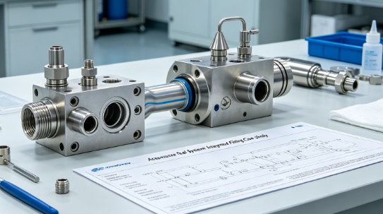
Real-World Case Study: Aerospace Fuel System Integrated Fitting
Part Background
Monolithic Ti6Al4V aerospace fuel manifold fitting, integrated main shaft + 6 angled cross ports + tapered sealing thread + hexagonal wrench flats, AS9100 flight-critical specification, total runout ≤0.005mm, leak-tight UHV sealing surface
Original Legacy Process
- Separate lathe turning + 5-axis milling + multiple re-fixturing, total cycle time 78 mins, 12% scrap rate from runout errors, leak test failures, and tolerance drift
Implemented Hybrid Mill-Turn Solution
- Mazak multi-tasking mill-turn single-setup workflow, B/Y/C axis 5-axis milling, servo steady rest support, validated NX mill-turn CAM + full machine simulation
- Pre-stress-relieved Ti6Al4V bar, high-pressure coolant titanium turning, thread whirling for tapered sealing threads
- On-machine probing + thermal compensation; post finish validation CMM + helium leak testing
- Full AS9100 traceability documentation, permanent laser UDI marking on non-critical flange
Results
- Total cycle time reduced to 36 mins (54% cycle time reduction)
- Total runout controlled ≤0.004mm, zero leak test failures
- Scrap rate reduced to <0.5%, validated NADCAP process compliance
- Eliminated 3 secondary machining operations and manual assembly steps
FAQ
What is the core difference between mill-turn multi-tasking and separate lathe + 5-axis machining?
Hybrid mill-turn machines use a unified spindle datum for all turning + milling + 5-axis contouring in a single setup, eliminating re-fixturing tolerance stack-up, critical for runout/concentricity specs. Separate processes introduce cumulative positional errors and longer cycle times, but may be more cost-effective for large low-precision non-integrated parts.
When to choose Swiss-type mill-turn vs general horizontal mill-turn?
Swiss mill-turn: long, slender, small-diameter high-precision medical/dental/valve micro-components (L/D high ratio). General horizontal mill-turn: larger heavy integrated shafts, flanged aerospace/energy components, low L/D ratio big workpieces.
How to prevent mill-turn collisions with B-axis / sub-spindle / turret tooling?
Use full 3D machine simulation CAM software with exact machine geometry (including turrets, steady rests, sub-spindle), dry-run simulation, slow single-block verification, and collision detection software. Never run new mill-turn programs directly at full speed.
Can mill-turn replace grinding for ultra-precision bearing race surfaces?
Yes, with hard turning (CBN inserts), thermal compensation, and controlled finishing cycles, mill-turn can achieve Ra <0.02μm and tight roundness specs for many bearing applications, reducing secondary grinding operations. For ultra-high-speed bearing races, a final precision grind pass may still be required.
How to manage residual stress distortion in large integrated mill-turn shaft parts?
Use staged roughing cycles + intermediate certified vacuum stress relief annealing (per AMS/ISO specs), followed by light finishing passes after thermal cycles, plus on-machine probing for thermal drift correction.
What is thread whirling in mill-turn machining?
A specialized multi-tooth live tool mill-turn process for complex tapered/medical helical threads (e.g., titanium hip stem tapers), producing superior thread form and surface finish vs single-point turning, critical for implant osseointegration and seal integrity.
Does mill-turn always lower total part cost?
No, for simple pure rotational parts (basic shafts with no prismatic features), standard 2-axis lathes are cheaper. Mill-turn delivers ROI for complex integrated rotational + prismatic parts with tight GD&T concentricity/runout specs and medium/high batch volumes.
What is the main spindle datum rule for mill-turn GD&T drawings?
All critical runout, concentricity, and angular position tolerances must reference the primary main spindle central axis (A datum), not secondary prismatic features, to ensure consistent inspection and machining alignment.
How to handle long slender mill-turn shafts to reduce chatter?
Use programmable servo steady rests, tailstock support, guide bushings (swiss), variable pitch milling tools, spindle speed variation (SSV), and limit deep radial milling cuts to reduce vibration and deflection.
What controller/post-processor validation steps are required for mill-turn CAM programs?
Validate post-processor with dry-run simulation, G-code verification, short test part trial runs, check C-axis/B-axis rotary travel limits, verify sub-spindle handoff logic, confirm G-code matches machine controller syntax (FANUC, Mazatrol, Siemens).
Quick Hybrid Mill-Turn Setup & Programming Checklist
Pre-Setup & Datum Validation
Pre-stress-relieved bar stock verified for straightness & MTR heat lot traceability
Main spindle / chuck / sub-spindle alignment calibrated, runout checked
Thermal compensation enabled, machine warm-up cycle complete
Unified main spindle A-axis datum defined on GD&T drawing
Full 3D machine simulation validated in CAM (B-axis, turret, steady rests, sub-spindle)
Tooling & Chatter Control
Short rigid live tool holders, variable pitch fluted end mills, vibration-damped boring bars
High-pressure through-tool coolant enabled for Ti/Inconel alloy runs
Servo steady rest / tailstock configured for slender shaft sections
Tool wear monitoring enabled; validated thread whirling cycles
Spindle speed variation (SSV) programmed for resonant chatter risk zones
Programming & Process Sequencing
Rough turning first, followed by rough milling, then finish turning/milling
Similar-angle 5-axis features grouped to minimize B-axis rotary travel
Sub-spindle handoff validated with probing cycles; datum re-verified post-handoff
Adaptive trochoidal milling used for deep pockets/slots to reduce radial load
In-process probing cycles for critical runout/concentricity validation
Inspection & Compliance
CMM/roundness gauge validation of total runout, concentricity, cylindricity
Surface roughness / thread profile validation on critical sealing/fatigue surfaces
Regulated batches: AS9102 FAIR, batch travelers, heat treatment logs, traceability marking
SPC monitoring of critical GD&T features for mass production
First article validation + helium leak test (if fluid/vacuum service)
Safety & Dry Run
Full slow single-block dry run for new mill-turn programs
Collision check complete, emergency stop verified
Balanced spindle parameters validated for high-speed turning cycles
Chip evacuation / coolant filtration system verified for alloy material runs
Closing Wrap-Up
Hybrid mill-turn multi-tasking machining is the gold standard for high-precision monolithic integrated rotational + prismatic workpieces, where runout, concentricity, and angular GD&T specs are mission-critical. The biggest payoff comes from a unified main spindle datum workflow, smart chatter suppression, validated CAM simulation, and regulated traceability/metrology validation.
When applied correctly, hybrid mill-turn reduces cycle time, eliminates assembly joints, improves fatigue performance, and delivers repeatable micron-level precision for aerospace, medical, energy, and motorsport integrated components. The key risk is unvalidated CAM programming (collisions) and uncontrolled chatter/residual stress distortion—both solved with simulation, steady rest support, and staged machining workflows.
If you need a validated mill-turn CAM template (NX/Mastercam) for titanium integrated shaft geometry, share your part specs and machine model for a free DFM review.


