
Published:Zorapid.Ltd
Modern UAV (Unmanned Aerial Vehicle / Drone) airframes require ultra-light, high-stiffness monolithic aluminum chassis: complex curved geometry, integrated hardpoints, sensor cutouts, battery cavities, thin webs, and precision mount interfaces for cameras, gimbals, motors, and avionics.
5-axis CNC machining is the primary manufacturing method for high-performance industrial, long-endurance, and military UAV frames, enabling single-setup production of complex contoured geometry, precise mating interfaces, and optimized weight-saving lattices/webs that 3-axis machining cannot produce.
Key goals: maximize stiffness-to-weight ratio, minimize residual stress distortion, control thin-wall chatter, maintain GD&T precision for vibration-sensitive avionics mounts, manage corrosion risk, and meet aerospace/UAS compliance standards (AS9100, RTCA DO-160, FAA).
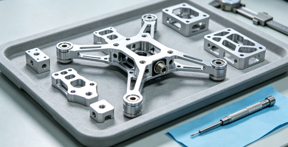
Common UAV Frame Aluminum Alloys & Material Specs
Primary Alloys
- 7075-T6 / T651 (Al-Zn-Cu) – Dominant High-Performance UAV Alloy
- High specific strength, ideal for primary load-bearing frames, main chassis, fuselage ribs, arms
- Risk: high residual stress, prone to warpage, corrosion susceptible, strict stress-relief requirements
- T651 = pre-stress-relieved plate (preferred over raw T6 for dimensional stability)
- 6061-T6 / T651 – General & Smaller UAV Frames
- Lower strength, easier machining, better corrosion resistance, lower residual stress, good for secondary frames, payload brackets, consumer UAVs
- Lower cost, excellent anodizing quality
- 6063, 2024-T3 – Secondary structures, stringers, longeron components
- 2024-T3: fatigue-resistant for cyclic vibration arms; 6063: simple extruded frame parts
- Material Pre-Requisite: Use pre-stress-relieved plate/blanks, verify MTR mill test reports, full heat lot traceability for military/commercial certified UAV programs, XRF alloy validation for critical flight hardware.
Key UAV Frame Design Metrics
- Core Drivers: Weight reduction (thin webs 0.8–1.5mm typical), torsional stiffness, vibration damping, mount positional accuracy, crash durability, corrosion resistance
- Critical GD&T: Motor mount bolt pattern concentricity, gimbal interface flatness, avionics connector hole positions, payload datum alignment
Unique 5-Axis UAV Frame Machining Challenges
- Ultra-Thin Web Geometry: Large thin panel structures, deep pockets, variable wall thickness → severe chatter, deflection, vibration resonance, dimensional drift
- Complex Freeform Contours: blended aerodynamic surfaces, compound angles, sculpted arm transitions → 5-axis collision risk, long cycle times, tool reorientation errors
- Residual Stress Distortion: 7075 aluminum has high locked-in residual stress; heavy asymmetric material removal causes slow post-machining warpage
- Vibration Sensitivity: UAV frames operate under high cyclic vibration; micro-notches, poor surface finish, residual tensile stress lead to fatigue cracking and vibration resonance
- Large Asymmetric Blank Geometry: oversized frame blanks, deep pocketing, long cantilever arms → fixturing instability, poor repeatability
- Corrosion Risk & Anodizing Dimensional Shift: thin aluminum walls can distort during anodizing; mask precision datums/mounting surfaces
- Regulatory & Traceability Requirements: Commercial UAS/FAA, military DoD, AS9100 traceability, DO-160 environmental validation for certified platforms
Machine, Fixturing & Workholding Setup
Machine Requirements
- Full 5-axis CNC (trunnion / gantry / vertical 5-axis): rigid boxway construction, vibration damping, high-torque spindles, linear glass scales, thermal compensation, full 3D collision simulation software
- Trunnion 5-axis: ideal for mid-size UAV arms, payload frames, smaller fuselage ribs
- Gantry 5-axis: large fixed-wing UAV fuselage panels, wing ribs
- Enclosed temperature-controlled machine enclosures (±1–2°C) for precision avionics mount zones
- Spindle: high-speed HSK-A63 / HSK-F63, balanced high-RPM spindles (15k–24k RPM typical for aluminum)
- Full 3D machine simulation (Vericut, NX, Mastercam) to validate B/C axis travel limits and avoid catastrophic crashes
Fixturing & Workholding
- Custom Vacuum Fixtures (Primary for Large Thin Panels):
- Full-area vacuum pod / spoilboard fixturing to evenly support thin webs, reduce chatter/deflection
- Vacuum gaskets, sealant validation, pressure monitoring; avoid hard direct clamping on thin webs (indentation, distortion risk)
- Add sacrificial support ribs, honeycomb backing, or fixturing bridge structures for ultra-thin regions (removed in final light finishing passes)
- Datum Locator Jigs: 3-point repeatable fixture datums (pre-machined aluminum fixture plates), standardized fixture pin patterns
- Define primary datum on a thick central chassis spine (not thin arms/webs)
- Avoid clamping on final critical mount/gimbal datum zones
- Multi-Sided Fixturing Strategy:
- First setup: rough 5-axis pocketing + rough contouring on main side
- Second controlled setup: reverse side finishing, validated via probing to maintain datum alignment
- Minimize re-fixture count to reduce tolerance stack-up
- Balancing: validate spindle/workpiece balance for high-RPM aluminum machining to reduce vibration
5-Axis Tooling & Cutting Parameters for Aluminum UAV Frames
Tool Selection
- Tool Type: High-helix (35°–45°) 2/3 flute solid carbide end mills, polished / DLC coated (diamond-like carbon) for low friction, reduced BUE (built-up edge)
- Long reach areas: use vibration-damped extended tool holders, short tool overhang as much as possible
- Micro thin-wall finishing: small diameter fine-grain carbide, high helix, variable pitch flutes (chatter suppression)
- Drilling/tapping: high-speed aluminum drills, form taps, thread milling for motor mount holes
- Coolant & Lubrication:
- Water-soluble synthetic coolant, through-spindle high-pressure coolant (70 bar+) for chip evacuation, reduce heat buildup
- Mist lubrication for ultra-thin finish passes to minimize coolant-induced dimensional shift
- Full chip evacuation to prevent re-cutting chips, surface scratching, and chatter
- Filter coolant to remove fine aluminum swarf (prevents surface marring)
- Baseline 7075/6061 Aluminum 5-Axis Parameters (General):
- Rough Milling (Trochoidal High-Speed Machining – HSM):
- Spindle RPM: 12,000–20,000 RPM
- Feed Rate: 5–10 m/min
- Radial engagement: 10–15% of tool diameter, light axial depth of cut, constant chip load adaptive cycles
- Trochoidal milling = critical to reduce radial load and residual stress
- Finish Milling (Thin Wall / Aerodynamic Surfaces):
- Light depth of cut (0.05–0.15mm), higher feed, controlled constant chip load
- Simultaneous 5-axis finish passes with smooth axis blending, reduce B/C axis jerk
- Spindle speed variation (SSV) for thin-wall chatter suppression
- Final Mirror Finish Pass: single light skim pass, minimal heat input
- Surface Finish Targets:
- Aerodynamic outer surfaces: Ra 0.8–1.6 μm
- Motor/gimbal/avionics mount datums: Ra 0.4 μm or better
- Internal non-critical webs: Ra 3.2 μm (reduce cycle time)
- Rough Milling (Trochoidal High-Speed Machining – HSM):
- Tool Monitoring: spindle load monitoring, periodic roughness validation, scheduled tool change cycles to avoid gradual thin-wall deflection/chatter
DFM Design Rules for 5-Axis UAV Frames
1. Thin Wall & Aspect Ratio Rules
- Minimum validated wall thickness: ≥1.0mm (6061), ≥1.2mm (7075) (avoid <0.8mm general production thin walls without sacrificial support geometry)
- Add gradual blended fillet transitions (R≥1mm) between arms, webs, and main chassis; eliminate sharp internal corners (fatigue risk + chatter hotspots)
- Avoid long cantilever arms with extreme L/D ratios (>15) without intermediate support ribs or DFM stiffener geometry
- Use gradient lattice/rib geometry validated via FEA simulation for weight reduction (not random micro-thin webs)
2. GD&T & Datum DFM
- Define unified primary datum on the thick central chassis spine (fixed for all 5-axis setups)
- Zone-based GD&T: tight tolerances only on motor mount, gimbal, avionics, payload datums; relax general aerodynamic/non-mating geometry to ±0.05mm baseline CNC tolerance
- Group common-angle 5-axis features to reduce continuous simultaneous 5-axis travel time and axis jerk
- Avoid deep blind pockets, full through-cuts in critical load paths, and unvalidated complex 5-axis undercuts
3. Material & Stock DFM
- Use standard plate sizes, pre-stress-relieved blanks (7075-T651), minimize asymmetric heavy pocketing
- Add sacrificial fixture lugs (non-flight geometry) to main chassis; remove lugs in final finishing passes
- Avoid full monolithic ultra-large single parts where modular assembly is validated (reduce rework risk, improve field repairability)
4. Anodizing Masking DFM
- Design defined masking zones on critical datum/mount surfaces (flat, easy-to-mask geometry)
- Add masking grooves/features for repeatable silicone masking fixtures
- Avoid thin critical mount webs where anodizing thickness variation will alter GD&T fit
5. Vibration DFM
- Validate FEA modal analysis to avoid resonant frequencies matching UAV flight vibration frequencies
- Add controlled stiffener patterns, avoid repetitive identical thin-web patterns that amplify vibration
Residual Stress & Dimensional Stability Control
- Staged Machining + Intermediate Stress Relief (Critical for 7075 UAV Frames)
- Step 1: Trochoidal rough 5-axis pocketing (light radial loading), remove bulk material in multiple passes to reduce asymmetric residual stress
- Step 2: Intermediate low-temperature stress relief annealing (7075: ~120°C–150°C, slow cool, validated cycle)
- Do not over-anneal (risk hardness reduction)
- Step 3: Light finish 5-axis machining after stress relief cycles
- Step 4: Post-finish soak validation (24–48hr ambient soak + CMM check) to detect delayed warpage
- Use adaptive trochoidal milling to minimize cutting-induced residual tensile surface stress
- Thermal Machine Control: enable machine thermal compensation, run spindle warm-up cycles, consistent ambient temperature
- SPC Monitoring: track key datum flatness, hole pattern positional tolerance over batches; flag drift early
- Avoid aggressive deep single-pass roughing that creates heavy residual stress in thin webs
Surface Finishing, Corrosion Protection & Anodizing
1. Deburring & Edge Breaking
- Controlled micro-brush deburring, vibratory tumbling (non-critical zones)
- Break sharp edges (R0.2–0.3mm) to eliminate fatigue crack initiation micro-notches
- No aggressive hand grinding (introduces residual stress, surface damage)
2. Anodizing (Primary UAV Corrosion Treatment)
- Type II Clear Anodize (general UAV), Type III Hard Anodize (high-wear motor mount zones only)
- Mask critical GD&T datum/mount surfaces with validated silicone masking jigs before anodizing
- Validate anodize thickness (10–25μm typical) to avoid dimensional shift on precision interfaces
- Post-anodize sealing (hot water / dichromate per specs), RoHS compliant
- Conduct salt spray testing (ASTM B117) for long-endurance / coastal UAV programs
3. Additional Coatings
- UV-resistant polyurethane topcoat for outdoor UAV airframes
- Conductive coating / IMI plating for EMC/EMI shielding on avionics bays (compliant with DO-160)
- Avoid full hard anodizing across entire thin frame (risk of warpage, brittleness)
4. Final Cleaning
- Ultrasonic solvent/DI water wash to remove coolant residue, prevent hidden corrosion
- Dry fully, apply corrosion inhibitor for long-term storage
Inspection, Traceability & Compliance
Dimensional Metrology
- CMM 3D GD&T inspection of critical datums, motor mount hole patterns, gimbal interfaces
- Optical 3D scanning (blue light scan) for full aerodynamic surface validation
- Profilometer surface roughness measurement on fatigue/vibration critical zones
- SPC statistical process control for key positional tolerances (avionics/motor mounts)
NDT & Material Validation
- XRF alloy verification, MTR heat lot traceability for certified UAS programs
- Dye penetrant inspection (DPI) for primary structural UAV frames (military/commercial certified platforms)
- Modal vibration testing for dynamic validation, fatigue cycle validation
Documentation & Traceability
- AS9100 / ISO9001 batch travelers, heat lot logs, FAIR (AS9102) first article inspection for regulated UAV programs
- UID / laser data matrix marking (non-fatigue zones) for traceability
- RTCA DO-160 environmental test validation (vibration, temperature, humidity) records
- Full revision control (PLM/ECO) for regulated UAS production, formal PPAP if required
Regulatory Compliance
- Commercial UAS: FAA 14 CFR, ASTM F3322 UAS standards
- Military UAS: DoD DFARS, AS9100, NADCAP special process compliance (if applicable)
- RoHS / REACH compliance for civil UAV electronics integration
Common Defects & Troubleshooting
- Thin Wall Chatter / Wavy Surface Finish
- Cause: excessive radial load, long tool overhang, resonant RPM, insufficient vacuum support, unbalanced spindles
- Fix: trochoidal HSM, SSV spindle speed variation, add sacrificial supports, shorten tool overhang, validate vacuum fixturing
- Post-Machining Delayed Warpage (7075 Common Issue)
- Cause: raw billet residual stress, aggressive roughing cycles, missing intermediate stress relief, asymmetric pocketing
- Fix: pre-stress-relieved blanks, staged roughing + validated low-temp stress relief, 24hr soak validation, SPC tracking
- Motor Mount Hole Pattern Tolerance Drift
- Cause: 5-axis axis drift, thermal variation, re-fixture error, residual stress
- Fix: thermal compensation, single-setup 5-axis where possible, datum probing cycles, SPC monitoring
- Fatigue Micro-Notches / Poor Surface Finish
- Cause: dull tools, BUE aluminum build-up, unvalidated finishing cycles, hand grinding
- Fix: DLC polished 2/3 flute carbide, scheduled tool changes, consistent finish passes, formal deburr SOP
- Anodizing Dimensional Shift / Masking Failure
- Cause: poor masking, full thin frame hard anodizing, unvalidated anodize cycles
- Fix: repeatable silicone masking jigs, zone selective anodizing, validate anodize thickness with gauges
- Chip Re-Cutting & Surface Scratches
- Cause: poor chip evacuation, insufficient coolant, re-entrant 5-axis geometry
- Fix: through-spindle coolant, high-speed trochoidal cycles, full chip evacuation simulation
Real-World Case Study: Long-Endurance Fixed-Wing UAV Fuselage Rib
Original Process
5-axis rough + finish single-pass deep pocketing, raw T6 plate, full hard anodize, 100% CMM full scan inspection
- Issues: severe chatter, 0.2mm post-machining warpage, 20+ hour cycle time, repeated rework, vibration fatigue failures
Revised 5-Axis DFM & Machining Workflow
- Pre-stress-relieved 7075-T651 plate, FEA validated gradient rib DFM with 1.5mm minimum wall thickness, blended R1.5mm fillets
- Trochoidal high-speed roughing + intermediate low-temperature stress relief
- 5-axis single-setup finish with vacuum spoilboard fixturing, variable pitch DLC carbide tools, SSV chatter suppression
- Silicone masking of central datum zones, selective Type II clear anodizing only
- CMM SPC sampling validation, 24hr soak dimensional check, DPI NDT structural validation
Results
- Total cycle time reduced 35%, residual warpage reduced to <0.03mm
- No vibration fatigue failures in 1,000+ flight hours, consistent gimbal mount positional tolerance
- Passed DO-160 vibration/environmental testing, FAA UAS compliance validation
FAQ
Which aluminum alloy is best for high-performance long-endurance UAV main frames?
Pre-stress-relieved 7075-T651 for primary load-bearing frames, validated via FEA and vibration fatigue testing. 6061-T6 is suitable for smaller consumer/secondary UAV frames for cost and corrosion balance. Avoid non-stress-relieved raw 7075-T6 for large monolithic frames due to severe residual stress warpage risk.
How to reduce 5-axis UAV frame thin-wall chatter?
Use vacuum spoilboard fixturing + sacrificial support ribs, trochoidal high-speed milling, variable pitch fluted carbide tools, spindle speed variation (SSV), light finish passes, and minimize tool overhang. Validate FEA modal analysis to avoid resonant frequencies.
Can full monolithic 5-axis UAV frames replace bolted multi-part frames?
Yes for small/medium UAVs to reduce vibration and assembly error, but add formal residual stress validation and consider modular DFM for large fixed-wing UAVs for field repair and manufacturing lead time balance.
What anodizing type for UAV airframes?
Type II clear anodize for general UAV outer frames; limited Type III hard anodize only for high-wear motor mount zones (not thin webs). Always mask critical GD&T datums to avoid dimensional shift and validate thickness.
How much post-machining soak validation time is needed for 7075 UAV frames?
24–48 hours ambient soak followed by CMM critical GD&T check to identify delayed residual stress warpage before anodizing and assembly.
What 5-axis simulation software is essential for complex UAV frame geometry?
Full machine simulation software (Vericut, NX CAM Simulation) including trunnion/B-axis travel limits, fixturing, and spoilboard geometry to eliminate 5-axis collision risk and validate finish passes.
How to balance weight reduction and manufacturability for UAV frames?
FEA gradient rib DFM (not arbitrary ultra-thin webs), set validated minimum wall thickness, add blended fillets, reduce non-critical 5-axis continuous zones, and use zone GD&T tolerancing. Validate fatigue/vibration performance with physical testing, not just simulation.
Do I need NADCAP for civilian commercial UAV frames?
Typically not mandatory unless specified by the prime / FAA certified program, but formal AS9100 traceability, FAIR, and SPC validation are strongly recommended for BVLOS (beyond visual line of sight) UAS operations. Military UAV programs follow formal NADCAP/DoD specs.
What is the typical surface roughness target for UAV gimbal/motor mount datums?
Ra ≤0.4μm for precision gimbal/motor mount datums to reduce micro-vibration and maintain gimbal stability; Ra 0.8–1.6μm for general aerodynamic surfaces for drag and corrosion balance.
How to manage 5-axis UAV frame production lead time?
DFM zone GD&T rationalization, pre-stress-relieved blanks, validated repeat 5-axis CAM programs, vacuum spoilboard repeat fixturing, reduce full-batch 100% CMM inspection to SPC sampling validation, schedule anodizing in parallel where possible (masked zones).
Quick 5-Axis UAV Frame Machining Checklist
Material & DFM Pre-Check
Pre-stress-relieved aluminum blank (7075-T651 / 6061-T651), MTR heat lot traceability validated
FEA validated minimum wall thickness (≥1.2mm for 7075), blended fillets R≥1mm
Unified primary datum defined on thick central chassis spine, color-coded zone GD&T
DFM sacrificial fixture lugs / vacuum spoilboard geometry designed upfront
Modal FEA vibration check completed to avoid UAV flight resonant frequencies
5-Axis Machine & Fixturing Setup
Full 5-axis machine simulation validated (Vericut/NX), B-axis travel limits verified
Vacuum spoilboard / pod fixturing validated, pressure monitoring enabled
Spindle warm-up cycles + thermal compensation enabled, spindle balance checked
Short rigid DLC 2/3 flute carbide tooling, minimal tool overhang configured
Trochoidal high-speed roughing cycles programmed, adaptive chip load enabled
Machining & Residual Stress Control
Intermediate validated low-temperature stress relief after roughing (7075 frames)
SSV spindle speed variation enabled for thin-wall finish passes, controlled light depth of cut
High-pressure through-spindle coolant enabled, chip evacuation validated
24–48hr post-finish soak validation + CMM critical GD&T check
SPC monitoring of motor/gimbal mount positional tolerances
Finishing & Corrosion Protection
Controlled micro-deburr / edge breaking (R0.2–0.3mm), no aggressive grinding
Repeatable silicone masking jigs for critical datum zones before anodizing
Selective anodizing (Type II clear general), validate coating thickness
Full ultrasonic cleaning, post-anodize sealing, corrosion validation (ASTM B117 if required)
Conductive/EMI coating applied for avionics bays per DO-160 specs
Inspection & Compliance
CMM GD&T validation of critical motor/gimbal mount features, SPC sampling setup
DPI NDT / fatigue validation for primary structural UAV frames (regulated programs)
AS9102 FAIR, batch travelers, MTR logs, traceability UDI marking complete
Environmental/DO-160 vibration validation documentation (certified UAV programs)
RoHS/REACH compliance validation, formal ECO revision control
Closing Wrap-Up
5-axis aluminum UAV frame manufacturing balances aerodynamic geometry, ultra-lightweight DFM design, thin-wall chatter suppression, residual stress control, vibration fatigue performance, and UAS regulatory compliance. The biggest risks are 7075 residual stress warpage, thin-wall chatter, vibration resonance, and anodizing datum distortion—not raw 5-axis speed.
Adopt vacuum spoilboard 5-axis fixturing, trochoidal high-speed roughing, validated staged stress relief, zone GD&T DFM rules, and formal soak validation for consistent dimensional stability and flight reliability. Always validate DFM weight reduction changes via physical vibration/fatigue testing, not purely FEA simulation.
If you share a UAV frame STEP file and alloy/batch specs, I can create a validated 5-axis rough/finish CAM template and DFM review.


