
Published:Zorapid.Ltd
30–50% of CNC lead time waste stems directly from poor CAD design choices—not spindle speed or machine capacity. Common issues: global micron tolerances, excessive continuous 5-axis geometry, extreme thin walls, unplanned rework, ambiguous GD&T, repeated drawing revisions, and over-specified special processes.
These DFM hacks focus on design changes that reduce setup time, cycle time, inspection time, rework risk, and validation delays, while preserving critical functional/regulatory specs. When applied systematically, they reliably cut total end-to-end CNC lead time by ~30% without sacrificing core performance, fit, or compliance.

Zone-Based GD&T Tolerance Rationalization (Biggest Single Win)
Problem
Global blanket tight GD&T tolerances force full-batch slow finishing cycles, 100% CMM inspection, repeated slow passes, and frequent scrap/rework—even for non-mating, non-fatigue, non-cosmetic surfaces.
DFM Hack
- Color-Code Two Core Zones in CAD:
- Critical Zones: Sealing flanges, threaded bores, bearing interfaces, regulatory/fatigue paths, mating datums – retain validated tight GD&T specs, SPC monitored
- General Zones: Non-mating outer geometry, hidden pockets, non-load surfaces – relax to standard CNC baseline tolerances (e.g., ±0.05mm linear, ±0.3° angular, Ra 1.6/3.2μm)
- Use formal ECO change control + tolerance stack-up / Monte Carlo validation to confirm no assembly/fatigue risk
- Limit 100% CMM full inspection only to critical zones; use SPC sampling for general geometry
- Define a unified primary datum (A-axis spindle datum for mill-turn/rotational parts) to eliminate re-fixture alignment delays
- Document all tolerance changes via FMEA/DFMEA and formal PLM revision control (critical for regulated aero/medical/IATF parts)
- Typical Lead Time Impact: −10–15% total lead time by cutting long full-batch CMM inspection + slow finishing cycles
Feature Standardization & Prismatic Simplification
Problem
Random unique radii, odd hole sizes, custom threads, scattered micro blind holes, arbitrary freeform sculpting increase CAM programming time, tool changeovers, custom fixturing, and chatter risk.
DFM Hacks
- Standardize Core Geometry Library:
- Fixed radii (e.g., R3, R5), standard hole sizes, industry fastener/thread specs (avoid one-off custom threads)
- Consolidate hole patterns to repeat drill depths, reduce unique tool count and spindle idle changeover time
- Eliminate non-functional freeform sculpting; convert non-critical complex surfaces to prismatic 3-axis machinable geometry
- Remove unnecessary blind micro-holes, tiny deep pockets, redundant stiffeners, and duplicate fastener patterns validated unnecessary via FEA
- Add consistent fillet transitions to reduce residual stress and slow micro-finishing passes
- Avoid sharp internal corners requiring slow EDM/micro-machining cycles
- Typical Lead Time Impact: −5–8% via reduced CAM setup time, fewer tool changes, faster 3-axis machining cycles
Reduce 5-Axis Continuous Machining Zones
Problem
Full-part continuous 5-axis simultaneous machining = slow feed rates, long simulation cycles, high risk of collision/chatter, long validation dry-runs, and expensive runtime.
DFM Hacks
- Partition Geometry:
- Use indexed 5-axis / 3-axis prismatic machining for majority geometry; restrict only validated critical contours to continuous 5-axis cycles
- Group identical-angle 5-axis features to minimize B/C-axis rotary travel, reduce idle rapid movement and axis jerk
- Avoid extreme deep 5-axis undercuts requiring custom side-fixtures, lifters, or repeated re-fixturing
- Add simple straight parting lines, avoid jagged complex parting geometry
- Validate 5-axis CAM with full machine simulation upfront to eliminate crash risk and repeated dry-run cycles
- Typical Lead Time Impact: −5–10% by reducing 5-axis cycle time, dry-run validation time, and rework risk
Optimize Wall Thickness & Aspect Ratios to Eliminate Chatter & Rework
Problem
Ultra-thin non-structural walls, extreme L/D slender features, uneven mass create chatter, deflection, residual stress distortion, slow feeds, and repeated rework/validation cycles.
DFM Hacks
- Enforce Minimum Validated Wall Thickness:
- Follow validated DFM minimum wall rules (aluminum ≥1.5mm, Ti/hardened steel ≥2mm) unless formally validated via FEA + physical testing
- Add temporary sacrificial support ribs for ultra-thin walls (removed in final light finish passes) to reduce chatter during roughing
- Limit unsupported aspect ratios (L/D): general <10; swiss mill-turn <20 with guide bushing; add steady rest/tailstock geometry features for long slender cores
- Balance mass for high-speed turning/mill-turn parts to reduce spindle vibration and unbalanced chatter
- Create uniform wall thickness to reduce uneven shrinkage/residual stress distortion and post-machining drift
- Specify pre-stress-relieved raw blanks upfront to reduce post-machining dimensional drift and rework
- Typical Lead Time Impact: −3–7% by reducing chatter rework, slow finishing passes, and repeated dimensional validation cycles
Add DFM Datum & Fixture Features Upfront
Problem
No defined primary datums = repeated probing, alignment cycles, custom one-off fixturing, tolerance stack-up, and slow setup validation.
DFM Hacks
- Design dedicated, thick, non-critical fixture datum pads, locating holes, and fixturing lugs in the base CAD geometry (not added post-hoc)
- Use repeatable 3-point locating geometry, standardized fixture hole patterns
- Keep primary datum surfaces flat, prismatic, non-fatigue zones; avoid fixturing on mirror/fatigue critical surfaces
- Create unified datum reference frame aligned to main spindle axis for mill-turn/rotational parts
- Leave controlled stock for datum finishing in early machining passes
- Avoid multiple conflicting datum systems in GD&T drawings
- Validate fixture geometry in early DFM reviews with manufacturing/CNC programmers
- Typical Lead Time Impact: −3–6% via faster setup, probing, FAI validation, and reduced re-fixture tolerance drift
Rationalize Material, Stock Blanks & Special Processes
Problem
Full-billet premium exotic alloys (Ti, PEEK, 316L VIM-VAR), blanket HIP/electropolish/100% NDT add massive third-party special process lead time
DFM Hacks
- Zone-Based Material Specification:
- Use standard commodity alloys (6061, 7075, 304) for general geometry; reserve premium alloys only for validated critical functional zones
- Use near-net pre-machined blanks, pre-stress-relieved bar stock, standard bar sizes to reduce heavy roughing cycles and raw material waste
- Hybrid DFM design: standard base body + precision inserts (not full monolithic premium billet)
- Restrict regulated special processes (HIP, NADCAP heat treat, electropolish, full NDT) to defined critical zones only, apply masking SOPs
- Schedule required third-party special processes (heat treat, NDT) early in the workflow, avoid last-minute full-batch validation cycles
- Separate baseline finish vs regulated finish zones to avoid full-batch slow cleanroom processing
- Typical Lead Time Impact: −3–8% via reduced exotic material lead time, reduced full-batch special process cycles, faster roughing
Eliminate Unnecessary ECO Revisions & Add Formal DFM Gate Reviews
Problem
Mid-production CAD changes, ambiguous drawings, missing 2D GD&T specs cause re-programming, re-fixturing, re-FAI validation, and unplanned rework (the #1 unpredictable lead time killer)
DFM Hacks
- Implement formal pre-release DFM gate reviews (design + CNC programmer + QA + supplier DFM engineer) before drawing lock and CAM programming
- Full annotated 2D GD&T + STEP files, material/finishing specs, FAI/PPAP rules defined upfront
- DFM checklist sign-off as a formal design gate
- Lock mass-production CAD via PLM/ECO systems (Windchill, PTC, Siemens PLM), separate prototype NPI drawings from mass-production drawings
- Create a validated baseline DFM mass-production revision, prevent accidental prototype geometry production runs
- Complete FAI/AS9102 validation once at baseline release, avoid repeated full FAI cycles for minor cosmetic revisions
- Formal change order process with lead time impact review and approval before implementation
- Typical Lead Time Impact: −5–10% by eliminating unplanned rework, re-FAI validation, and mid-batch re-programming delays
Prototype vs Mass Production DFM Split Drawings
Problem
NPI prototype validation geometry (test lugs, sensor mounts, fine validation features) is directly reused for mass production, carrying permanent slow-cycle prototype features
DFM Hacks
- Maintain two formal controlled CAD revisions:
- NPI Prototype CAD: Full validation geometry, tight test specs, for FEA/durability validation
- Mass Production DFM CAD: Remove prototype test geometry, rationalized tolerances, standardized features, validated via FAI/FAIR
- Document the DFM mass-production baseline via formal ECO and FAI validation
- Use validated repeat CAM/fixture setups only with the mass-production DFM drawing
- Keep prototype validation batches small to avoid mass production lead time disruption
- Typical Lead Time Impact: −5–7% by eliminating perpetual prototype-cycle slowdowns in mass runs
Common DFM Mistakes That Blow Up Lead Time
- Global ultra-tight GD&T across entire parts → full slow CMM + finishing cycles
- Unvalidated deep undercuts, non-axisymmetric 5-axis geometry requiring repeated re-fixturing
- Overly monolithic giant billet geometry with excessive 5-axis removal + total scrap risk
- Unvalidated ultra-thin walls / high L/D ratios → chatter, rework, delayed validation
- Ambiguous GD&T / missing 2D specs → repeated FAI rework, customer QA approval delays
- Blanket regulated special processes for non-critical zones → multi-day third-party batch delays
- Frequent mid-batch CAD ECO revisions → re-programming, re-fixturing, re-FAI validation
- No defined primary datums → repeated probing/alignment cycles and tolerance drift
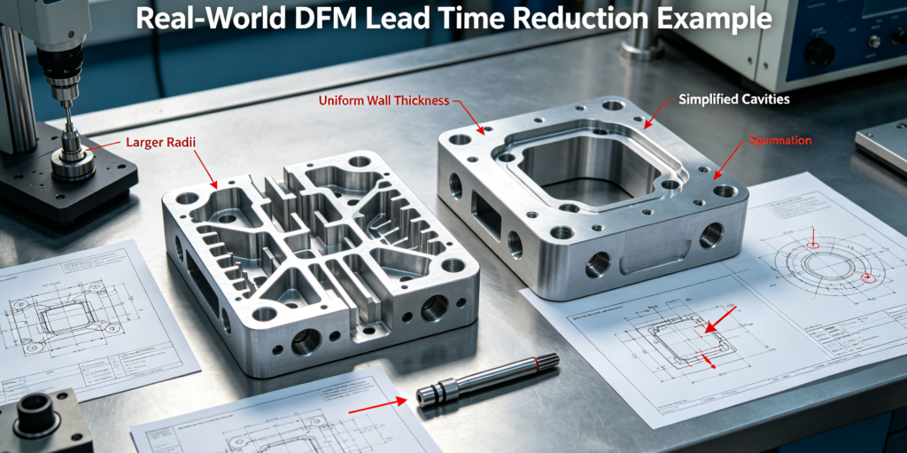
Real-World DFM Lead Time Reduction Example
Original Design
Full 5-axis monolithic 7075 aluminum EV bracket, global ±0.02mm tolerance, cosmetic freeform geometry, 100% CMM inspection, prototype test lugs retained
- Total Lead Time: 10 business days
DFM Changes
- Zone GD&T rationalization (general zones relaxed to ±0.05mm, only mounting datums tight)
- Convert non-critical freeform geometry to 3-axis prismatic features, reduce continuous 5-axis zones
- Remove prototype test lugs, standardize radii/hole patterns
- SPC sampling CMM inspection (not 100% full inspection)
Results
- Total Lead Time reduced to 7 days (30% reduction), validated NVH/durability unchanged, scrap rate reduced
- Annual production lead time savings: ~150+ production days, faster monthly volume fulfillment
FAQ
Can DFM alone achieve a consistent 30% CNC lead time reduction?
Yes when combining zone GD&T rationalization, 5-axis geometry partitioning, standardized prismatic DFM, locked mass-production drawings, and formal DFM gate reviews. Results are sustained when formal PLM change control and SPC validation are enforced.
How do I ensure DFM simplification does not risk regulated/aero/medical compliance?
Keep validated critical zone specs unchanged, complete DFMEA/tolerance stack-up analysis, formal FAI/AS9102 validation, and document all DFM changes via ECO/device history records (DHF).
How much lead time buffer should I keep after DFM optimization?
Keep 15–20% baseline buffer for third-party special processes, seasonality, and regulatory validation cycles; reduce unnecessary inspection/finishing buffers.
How do I communicate DFM changes to Asian CNC suppliers?
Use annotated color-coded 2D GD&T drawings + STEP files, formal ECO revisions, FAI validation, and bilingual SLA agreements; avoid verbal DFM changes.
What is the difference between DFM lead time optimization and over-engineering simplification?
DFM optimization preserves validated critical functional/regulatory specs while simplifying non-critical geometry. Over-simplification removes validated critical features, creating fit/fatigue risk. Always validate with FEA + physical testing.
When should DFM 5-axis reduction changes be applied?
During mass-production baseline DFM reviews, formal product revision cycles, and quarterly BOM cost reviews; never modify validated regulated critical mating/fluid zones without formal engineering approval.
How do I measure DFM lead time savings?
Track end-to-end job lead time via MES/job traveler software, split pre/post DFM baseline routings, measure total elapsed time (not just spindle runtime), and track rework/inspection cycle time separately.
Should I use DFM hacks for FDA/ISO13485 medical implants?
Yes, but only non-critical non-lattice/non-bone-contact zones, with formal DHF documentation, FMEA review, and full FAI validation; preserve validated lattice/implant interface specs.
How do I handle third-party heat treat/NDT bottlenecks with DFM?
DFM to reduce full-batch regulated validation by using zone-based sampling validation, schedule third-party processes upfront, and split regulated/non-regulated batches; do not shortcut regulated special processes.
What DFM hack works best for small-batch 5-axis aerospace prototypes?
Formal pre-release DFM review + zone GD&T + unified primary datum design, reduce repeated FAI/validation cycles, lock baseline CAM/fixture setups after first FAI validation.
Quick DFM Lead Time Reduction Checklist
GD&T & Tolerance DFM
Color-coded critical/general GD&T zones defined, validated via tolerance stack-up analysis
Non-critical geometry set to standard baseline CNC tolerances
Unified primary datum defined (aligned to spindle axis for mill-turn)
Full 100% CMM inspection limited only to validated critical zones
Regulated batches: formal FAI/AS9102 validation on baseline DFM drawing only
Geometry DFM
Standard radii, hole sizes, fastener specs across BOM
Non-critical continuous 5-axis geometry converted to 3-axis/prismatic
Excessive deep undercuts/extreme thin walls validated/remediated, add support geometry as needed
☐ L/D ratios controlled, steady rest/tailstock features added for long slender parts
Prototype test geometry removed from mass-production DFM CAD
Formal DFM gate review + checklist sign-off before CAM programming
Material & Special Process DFM
Premium alloys/special processes (HIP, electropolish, NDT) limited to validated critical zones
Pre-stress-relieved / near-net blanks used to reduce heavy roughing cycles
Masking SOP defined for regulated coating/finishing to avoid full-batch slow processing
Third-party special process batches scheduled early, validated vendor lead times documented
Drawing & Change Control DFM
Separate controlled NPI prototype CAD vs mass-production DFM CAD
Full annotated 2D GD&T + STEP files, complete specs up front
Formal PLM/ECO revision control, no mid-batch unapproved CAD changes
DFM baseline validated via FAI, SPC monitoring of critical GD&T features
DFM savings tracked via MES/job traveler lead time metrics
Fixture & Setup DFM
Dedicated standardized fixture datum lugs/holes designed into CAD
Fixture geometry validated with manufacturing team pre-production
Reduce unique tool count, consolidate similar features to minimize tool change time
CAM simulation validated to eliminate 5-axis collision risk and rework cycles
Closing Wrap-Up
30% CNC lead time reduction is achievable with structured DFM design rules—focus on zone-based GD&T rationalization, prismatic simplification, reducing unnecessary 5-axis cycles, datum DFM design, formal DFM gate reviews, and locked mass-production DFM drawings. The biggest lead time waste is non-critical geometry over-specification and unplanned revisions/rework.
Always validate DFM changes with engineering/QA/FMEA to avoid regulatory/fatigue risk, and track end-to-end lead time via MES to measure sustained DFM gains.
If you share a specific STEP file and batch/regulatory specs, I can do a 10-minute DFM review and flag the top 3 lead-time reduction changes.


