
Published:Zorapid.Ltd
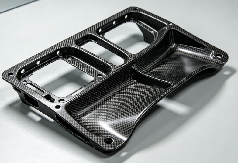
Aerospace interior CFRP (carbon fiber reinforced polymer) components include overhead bins, sidewall panels, ceiling panels, seat back structures, galley panels, stowage assemblies, and interior trim panels. These differ from primary flight structures: they are primarily secondary structural / semi-structural, with critical fire safety, FST, weight, vibration, fit-and-finish, and passenger comfort requirements, while still adhering to aerospace quality systems.
Core Governing Standards
- AS9100 (Rev D): Aerospace quality management system, process control, FMEA, risk management, traceability, first article inspection (FAI/AS9102)
- FAA / EASA Regulatory:
- FAA 14 CFR Part 25 (airworthiness standards for transport aircraft), FAR 25.853 (interior compartment fire safety)
- EASA CS-25, Airbus/Boeing internal material specs (BMS, AIMS, etc.)
- FST: FAA FAR 25.853 / ASTM E162 (flame spread), ASTM E662 (smoke density), ASTM E1995 (toxicity)
- Material & Composite Test Standards:
- ASTM D3171 (CFRP laminate properties), ASTM D5528 (delamination resistance), ASTM E2966 (composite damage inspection)
- NADCAP (PRI): applicable for NDT, special finishing processes (not always required for non-primary interiors, but required on regulated programs)
- ISO 2768: general dimensional tolerance standards, with program-specific tighter CTQ (critical-to-quality) feature tolerances
- RoHS/REACH, conflict minerals: environmental compliance for commercial aircraft programs
- OEM Specs: Boeing BMS, Airbus AIMS, aircraft interior FST composite material specs
Primary goals: Prevent delamination, matrix thermal degradation, fiber fraying, maintain FST performance, achieve consistent assembly tolerances, reduce vibration noise, and ensure full traceability.
CFRP Material Basics & FST Compliance
Common Aerospace Interior CFRP Types
- Epoxy Matrix Woven CFRP Panels (2/2 Twill, Plain Weave): General interior trim, overhead panels, sandwich honeycomb CFRP panels (NOMEX/aluminum honeycomb core + CFRP face sheets)
- Epoxy Tg (glass transition temperature): typically 120–180°C; avoid excessive cutting heat that softens/degrades matrix resin and ruins FST performance
- Low-density sandwich CFRP: core = Nomex honeycomb, thin CFRP skins for ceiling/sidewall panels (very prone to core crushing, skin delamination)
- Phenolic Matrix CFRP: High-priority fire zones (galley, lavatory surrounds), superior FST compliance per FAR 25.853
- Thermoplastic CFRP (PEEK/PEI): premium interior/galley structures; separate validated milling parameters (higher heat sensitivity, different chip behavior)
Material Validation Rules
- Raw material must have full MTR, laminate stack-up documentation, fiber orientation specs, FST test reports, batch traceability
- Verify FST compliance after milling/finishing: machining damage cannot degrade flame/smoke/toxicity performance (no deep subsurface delamination/matrix damage)
- Pre-mill inspection: C-scan UT NDT to confirm incoming panel integrity (no pre-existing delamination, core damage)
- Anisotropy risk: CFRP strength varies with fiber orientation (0°/90° vs ±45°); milling strategy must account for ply direction to reduce edge fraying and delamination
Core CFRP Milling Challenges
- Delamination & Ply Peeling: Interlaminar separation, push-out/pull-out delamination, edge fraying, fiber pull-out (major composite failure mode)
- Thermal Matrix Damage: Excessive heat > Tg → resin softening, charring, loss of FST performance, dimensional distortion
- Abrasive Tool Wear: Hard carbon fibers rapidly dull standard carbide tools, worsening fraying/delamination over time
- Thin Panel Vibration & Chatter: Large thin CFRP panels prone to vibration, resonant noise, inconsistent edge quality
- Conductive Carbon Dust Risks: Electrical shorting, machine electronics damage, respiratory hazards, contamination of adhesives/paint surfaces
- Honeycomb Core Damage: Core crushing, skin debonding on sandwich CFRP panels
- Dimensional Variability: Anisotropic thermal expansion, residual laminate stress, uneven clamping distortion
Machine & Fixturing Standards
Machine Requirements
- High-rigidity 3/5-axis CNC routers/machining centers, high-damping frames, linear glass scales, thermal compensation, closed-loop axis control
- Large gantry 5-axis routers for full-size cabin panels; trunnion 5-axis for smaller interior brackets
- High-speed spindles (15k–30k RPM), balanced HSK tooling, spindle load monitoring, collision simulation software
- Dust extraction system: local vacuum hoods, full machine enclosure, conductive grounding (CFRP dust is conductive/explosion risk)
- Dry/mist cooling setup: avoid full liquid flood coolant (epoxy laminates may absorb moisture, cause swelling, degrade adhesive/core bonds, ruin FST properties)
- Ambient temperature control (±2°C) to reduce thermal dimensional drift of large panels
Fixturing Standards
- Uniform, Low-Force Support Fixturing:
- Vacuum spoilboard / vacuum pod fixturing (primary for large thin CFRP panels), full-area backing sacrificial boards (MDF, phenolic, aluminum) to eliminate push-out delamination and core crushing
- 3-point datum locating, zero-point pallet systems for repeatability; avoid sharp hard clamping directly on thin CFRP skins
- Sacrificial backing plates / peelable backing films for edge trimming and through-feature milling
- For honeycomb panels: dedicated honeycomb support fixtures to prevent core crushing; avoid deep direct cutting into core structure
- Work Coordinate Rules: Unified primary datum defined on solid reinforced zones, not thin outer skins; automated probing cycles to set WCS offsets
- Clamping Validation: Verify no permanent panel deformation post-fixturing, no residual clamping stress warpage
- Simulation: Full CAM machine simulation (Vericut, NX, Mastercam) including fixturing, backing boards, tool holders to prevent collision damage
Approved Tooling & Milling Process Guidelines
Tooling Standards
- PCD (Polycrystalline Diamond) / Diamond-Coated Carbide Tools (Primary Production):
- Double helix, up-down (compression) spiral geometry (compression end mills): downward force on top ply, upward force on bottom ply, minimises edge delamination/fraying
- Sharp cutting edges, controlled rake angles (positive rake ~15°–20°), fine pitch geometry
- Router bits: diamond-tipped spiral trim bits for panel edge routing
- Avoid dull standard carbide tools; define formal tool life cycles, validated tool change schedules
- Anti-chatter variable pitch tools for thin large panels
- Tool Length: minimize tool overhang to reduce chatter; use shrink-fit/hydraulic holders for rigidity
- Validation: First article edge quality inspection (10× magnified visual check, UT NDT) for new tool types
Milling Strategy & Parameters
- Milling Mode: Climb milling (controlled), hybrid entry paths (helical ramping, arc entry) to eliminate vertical plunge delamination
- Multiple light shallow passes, not single deep passes, to reduce interlaminar shear stress
- Reduce axial depth of cut (ap): ~0.5–1.5 mm per pass; avoid deep aggressive routing
- High surface speed (vc: 500–750 m/min), moderate low feed per tooth (fz: 0.05–0.08 mm/tooth) to shear fibers cleanly rather than tear them
- Dry + cold compressed air / MQL (minimum quantity lubrication) cooling to control heat without matrix moisture uptake
- Spindle speed variation (SSV) to suppress thin-panel resonant chatter
- Finish edge passes with a fine PCD compression tool for clean edge definition
- Final edge break: controlled micro-edge break (per drawing spec, e.g., 0.2–0.3mm radius), no aggressive sanding (avoids subsurface damage and FST degradation)
- Honeycomb CFRP Special Rule: Skin trimming only; separate core machining with dedicated honeycomb tools; always use full backing support
- Post-Process Surface Treatment: Mask critical FST surfaces; only use validated aerospace interior paints/primers compatible with base CFRP FST specs; perform adhesion testing (ASTM D3359 cross-hatch test)
- Thermal Control: Continuous cold air blast; monitor spindle/part temperature to keep below Tg; avoid dwell cutting (localized hotspots)
Edge Quality Acceptance Criteria
- Visual inspection (10× magnification): No visible ply separation, continuous fraying, matrix charring, or fiber pull-out exceeding program-defined limits
- Delamination testing: Ultrasonic C-scan, tap test, flash thermography for subsurface delamination (per ASTM E2966); reject parts with unacceptable subsurface damage
- Dimensional Tolerance: Follow ISO 2768 or drawing CTQ specs (typical ±0.05mm for assembly features, tighter for fixture holes)
- Surface Finish: Consistent non-abrasive edge finish, compliant with interior NVH/vibration specs
DFM Design Rules for Aerospace Interior CFRP
- Fiber Orientation DFM: Specify laminate stack-up and fiber directions on drawings; align critical edges/holes to reduce cross-fiber cutting and fraying
- Minimum Radii: Add blended fillets (R≥1mm); avoid sharp internal corners (chatter, stress risers, localized delamination)
- Wall/Panel Thickness: Define minimum skin thickness; add local solid CFRP reinforcements for fastener/hinge mounting zones (avoid direct fastener holes in ultra-thin skins)
- Design sacrificial backing zones and fixture lugs (removed after final trimming)
- Hole Features: Use helical 5-axis milling for through holes, add backing plates, avoid direct vertical drilling; specify countersink depth tolerance
- FST DFM: Do not remove primary fire barrier CFRP core/skin material; maintain minimum specified laminate thickness in FST-critical zones
- Assembly DFM: Add consistent edge break, eliminate sharp exposed edges (passenger safety); design modular panels to reduce large single-piece fixture risk
- Vibration DFM: FEA modal analysis to avoid cabin resonant frequencies; add damping features per OEM interior noise specs
Inspection, NDT & First Article Validation Standards
1. First Article Inspection (FAI)
- AS9102 FAI: Full dimensional CMM/laser scan validation, ballooned drawings, GD&T verification, Cpk capability studies (Cpk ≥1.33 for CTQ assembly features)
- Edge quality inspection: magnified visual inspection, delamination measurement, surface roughness validation
- FST verification: periodic batch FST testing (ASTM E162, E662, E1995) to confirm milling does not degrade fire/smoke performance
- Material verification: XRF/composite material validation, MTR batch cross-check
2. Routine Inspection & NDT
- Visual inspection (10× loupe) 100% for all visible edges
- Sampling NDT: Ultrasonic C-scan (UT), flash thermography, tap testing for subsurface delamination (per customer sampling plan, AS9100 control plans)
- Dimensional SPC monitoring, gage R&R validation per IATF/AS9100
- Batch traceability: MES job travelers, unique part ID/UID marking (non-FST zones only), full process logs (machine parameters, tool changes, NDT results)
- Regulatory Records: Archive records per aircraft OEM/aerospace requirements (7+ years typical for commercial aircraft programs)
3. Environmental Validation (Periodic)
- Accelerated thermal cycling, humidity testing per OEM interior specs
- Vibration/noise testing to meet cabin NVH specs
- Adhesion validation for paint/coating systems
Occupational Safety & Dust Control Standards
- Conductive Carbon Dust Risk Control:
- Continuous local vacuum dust extraction, grounded machine/ductwork, anti-static hoses, conductive floor matting (prevent static discharge/spark risk)
- Enclosed machining zones, regular machine/electronics cleaning to prevent carbon dust shorting
- Dust filter validation and maintenance schedule
- PPE & Industrial Hygiene:
- N95/P100 respirators, eye protection, anti-static gloves, conductive protective clothing
- Industrial hygiene air sampling for respirable carbon dust (OSHA/EU workplace exposure limits)
- Fire risk mitigation: carbon dust explosion risk assessment, inert gas suppression systems, housekeeping schedules
- Waste Disposal: Regulated composite waste disposal per local environmental rules, segregated composite waste streams
- Electrical Safety: Regular machine wiring checks, ESD grounding validation
Traceability & Quality System Requirements
- AS9100 Compliance: Process control plans, PFMEA, control charts, layered audits, corrective action (8D) processes, operator training records
- Material lot traceability: every part linked to raw CFRP batch, MTR, FST report, laminate stack-up record
- Change control (ECO/ECO revision process): formal validation of CAM programs, tooling, process parameters before serial production
- Document control: locked validated CAM templates, process sheets, FAI reports
- Regulatory Documentation:
- Material declarations, RoHS/REACH, conflict mineral reports, FST test certificates
- Supplier audit records (AS9100 audits, periodic composite process audits)
- PPAP approval (if required by auto/aerospace OEMs)
- Process Validation:
- Formal composite milling process qualification (process FMEA, capability studies)
- Annual re-qualification, re-FAI after material/tool/machine changes
- Preventive maintenance schedule (spindle calibration, axis laser calibration, vacuum system validation)
Common Defects & Corrective Actions
- Edge Delamination / Fraying / Fiber Pull-out
- Root: dull tools, incorrect feed/speed, direct vertical plunge milling, insufficient backing support, wrong fiber orientation cut direction
- Fix: PCD compression spiral tools, helical ramping, sacrificial backing, multiple shallow passes, climb milling, validate tool life cycles
- Matrix Charring / Thermal Damage
- Root: excessive feed/speed, poor cooling, dwell cutting, dull tools, exceeding resin Tg
- Fix: cold air/MQL cooling, reduce depth of cut, validated PCD tools, eliminate dwell cycles, monitor temperature
- Honeycomb Core Crushing / Skin Debonding
- Root: inadequate backing support, deep direct core milling, excessive clamping force
- Fix: full sacrificial backing, dedicated honeycomb tooling, reduce axial depth of cut, validate fixturing
- Vibration Chatter / Poor Edge Finish
- Root: thin panel resonance, long tool overhang, unbalanced spindles, rigid fixturing deficiency
- Fix: SSV spindle variation, anti-chatter PCD tools, vacuum spoilboard support, spindle balance checks, modal DFM validation
- Dimensional Drift / Panel Warpage
- Root: residual laminate stress, thermal drift, uneven clamping, FST coating dimensional shift
- Fix: ambient temperature control, thermal compensation, validated vacuum fixturing, post-mill soak validation, SPC monitoring
- FST Performance Degradation
- Root: deep subsurface delamination/matrix damage, excessive heat degradation
- Fix: periodic FST batch validation, NDT sampling, formal process validation
Quick Compliance Checklist
Quick CFRP Aerospace Interior Milling Checklist
AS9100 QMS, FST material MTR/FAR 25.853 documentation validated
Raw CFRP NDT pre-inspection (UT/C-scan), laminate stack-up/FST specs documented
PCD compression spiral tooling selected, formal validated tool life cycles defined
Full backing/sacrificial fixturing, vacuum spoilboard validated for thin/honeycomb panels
Dry/cold air/MQL cooling, no full liquid flood coolant, matrix Tg monitored
Multiple shallow passes, helical ramping entry, climb milling strategy programmed
Full CAM simulation, collision validation, spindle warm-up/thermal compensation enabled
10× magnified edge inspection + periodic NDT (UT/thermography) delamination checks
AS9102 FAI/FAIR completed, SPC Cpk monitoring of CTQ assembly features
Full batch traceability (MTR, MES logs, UID), FST periodic validation completed
Carbon dust extraction/ESD safety system validated, operator training records archived
FAQ
Can I use standard carbide end mills for aerospace interior CFRP production?
Not for serial production. Standard carbide dulls rapidly, causes fraying/delamination and risks FST degradation. Use PCD diamond-coated compression spiral tools for validated long-term quality. Short-run prototyping may use fresh sharp carbide with strict edge inspection.
What is the primary difference between interior CFRP milling and primary structural CFRP milling?
Interior CFRP prioritises FST compliance, passenger safety, NVH noise, fit-and-finish, and assembly tolerances, while primary structures focus on fatigue/life integrity. Interior panels also use large thin/honeycomb CFRP and require strict fire-safety validation rather than full structural NADCAP NDT (unless specified).
Is full wet coolant acceptable for epoxy aerospace interior CFRP milling?
Generally no. Liquid coolant can penetrate laminate/honeycomb bonds, absorb into epoxy resin, cause swelling/dimensional drift, degrade FST performance and core adhesion. Use cold compressed air / MQL minimum quantity lubrication only.
How often should FST compliance be verified on milled CFRP interior panels?
Per OEM/batch sampling plan (typically periodic batch testing, material lot change validation, major process change validation), in addition to routine NDT delamination inspection, to ensure milling does not compromise fire safety.
Do all aerospace interior CFRP panels require full C-scan UT NDT inspection?
Not 100% full scan for non-cabin-fire critical trim panels, but formal sampling NDT (thermography/tap/UT) per AS9100 control plans and OEM specs; full NDT for galley/lavatory FST-critical panels.
How to manage residual stress warpage of large thin CFRP panels?
Controlled vacuum spoilboard fixturing, ambient temperature control, thermal compensation, post-mill ambient soak validation, SPC dimensional monitoring, avoid asymmetric deep edge trimming, follow laminate residual stress relief guidelines if specified.
Closing Notes
Aerospace interior CFRP milling success hinges on FST regulatory compliance, delamination prevention, validated PCD tooling strategies, AS9100 process control, carbon dust safety management, and full traceability. The highest risk is hidden subsurface delamination and matrix thermal damage that compromises fire safety and long-term cabin integrity, even if visual edge quality appears acceptable. Always validate new CAM/tooling processes with FAI + NDT before serial production.


