
Published:Zorapid.Ltd
What Is 5-Axis Machining & Why It Matters
Core Definition
5-axis CNC machining controls 3 linear axes (X, Y, Z) + 2 rotary axes (A/B/C). There are two primary modes:
- 3+2 (positional 5-axis / indexed 5-axis): Rotate the part/spindle to a fixed angle, then run 3-axis cutting. Easier for beginners, great for angled holes, multi-sided pockets, mold cavities.
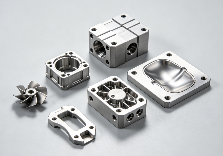
- Full simultaneous 5-axis: All 5 axes move continuously, for freeform surfaces, turbine blades, impellers, medical implants, deep curved cavities, conformal molds
Key Benefits
- Reduce multiple re-fixturing setups → less tolerance stack-up, higher accuracy, faster lead times
- Keep tool normal (perpendicular) to curved surfaces → better surface finish, shorter cutters, less chatter
- Reach deep undercuts, compound angles, and complex lattices impossible with 3-axis
- Critical industries: aerospace, medical implants, mold & die, motorsport, UAV, energy components
Key Risks for Beginners
- Machine collision (crash): #1 risk—costly spindle/frame damage, scrapped high-value parts
- Wrong post-processors, incorrect pivot points, unvalidated rotary kinematics
- Residual stress distortion, chatter, gouging (tool digging into the finished surface)
- Uncontrolled heat, poor surface integrity, long validation cycles for regulated parts
Learning Tip
Start with 3+2 positional 5-axis first, master simulation, then progress to full simultaneous 5-axis. Do not jump straight to lights-out unattended production.
5-Axis Machine Configurations & Core Terminology
Common 5-Axis Machine Types
- Trunnion (Dual Rotary Table / Table-Table): Two rotary axes on the worktable (A/C or B/C). Great for medium precision aerospace/medical parts, most common entry production 5-axis.
- Head-Table (Spindle Head + Rotary Table / B-C): One rotary spindle head + one rotary table; flexible for deep cavities, mold work.
- Dual Head (Head-Head): Both rotary axes on the spindle; high speed, limited work envelope.
- Gantry 5-Axis: Large format for aircraft panels, big molds, composite structures.
- Turn-Mill 5-Axis: Combined lathe + 5-axis milling for valve bodies, shafts, complex rotary parts
Core Terms
Key Fundamentals: RTCP, Work Coordinates & Post-Processors
RTCP Best Practice
- Enable RTCP mode in CAM and CNC controller; verify with simple test cuts (e.g., a sphere or flat circle)
- Always validate pivot offsets and kinematic parameters after machine service, axis calibration, or post-processor updates
- Avoid manual G-code editing for simultaneous 5-axis programs—edit in CAM and re-simulate
Work Coordinate Setup
- Define a unified primary datum (WCS origin) on a thick, stable central feature (not thin walls or fragile geometry)
- Use touch probes/3D probes for automated work offset setting and periodic drift correction
- Use zero-point fixturing systems (quick-change pallets) for repeatable offsets across multiple jobs
- Document WCS offsets, tool offsets, and fixture offsets in your CAM template/job traveler
Post-Processor Validation
- Request a validated machine-specific post-processor from CAM vendor/machine builder
- Run a simple test program (sphere, square, angled pocket) and measure with CMM/3D scanner
- Use full digital twin simulation (Vericut, NX, Fusion 360 simulation) to verify G-code before running on the machine
- Archive post-processors, lock versions, avoid untested post-processor edits
CAD/CAM Workflow & 5-Axis Toolpath Strategies
Main 5-Axis CAM Software
- Fusion 360: Entry-friendly, integrated CAD/CAM, great for 3+2 and simple simultaneous 5-axis, prototyping
- Mastercam: Popular job-shop 5-axis, swarf milling, mold machining
- NX CAM: Aerospace/medical high-end simultaneous 5-axis, impellers, regulated parts
- HyperMILL: Advanced 5-axis mold/blade finishing, automatic collision avoidance
- PowerMill: Deep cavity, hybrid, lights-out 5-axis machining
Core 5-Axis Toolpath Types
- 3+2 Positional Milling: Fixed angle tilt, 3-axis adaptive roughing, pocketing, drilling angled holes (beginner starting point)
- Adaptive/Trochoidal Roughing: Constant chip load, reduce shock, residual stress, and chatter (ideal for Ti, Inconel, aluminum)
- Simultaneous 5-Axis Finishing
- Morph/Swarf Milling: Align tool along curved surfaces for long edge finishing (blades, deep grooves)
- Flowline / UV Milling: Follow surface UV contours for mirror finish freeform geometry
- Collision-Aware Toolpath: Automatic tilt/tilt-away tool axis control to avoid holders/fixtures
- Rest-Machining / Residual Stock: Clean leftover material after roughing, reduce air cutting
- Drilling: 5-axis peck drilling for compound-angle deep holes, coolant-through drills, chip evacuation cycles
General CAM Workflow
- Import validated CAD (STEP/IGES), fix errors (gaps, bad faces), check GD&T specs
- Define stock model, fixturing geometry, tool library, material parameters
- Rough (3+2 adaptive trochoidal) → semi-finish → finish → deburr cycles
- Simulate full machine digital twin (including fixture, tool holders, full axis travel)
- Generate validated post-processed NC code, dry run in jog mode, verify axis movement
DFM Design Rules for 5-Axis Machining
Core DFM Principles
- Unified Primary Datum: Define one fixed WCS reference, avoid multiple conflicting datums
- Wall Thickness & Aspect Ratio
- Aluminum: ≥1.5mm minimum; Ti/hardened steel: ≥2mm minimum
- Avoid extreme unsupported L/D ratios (slender cores, deep thin walls) without sacrificial supports
- Add blended fillets (R≥0.5mm) to eliminate sharp corners (chatter, fatigue risk, gouging)
- Reduce Unnecessary Full Simultaneous 5-Axis Zones
- Use 3+2 indexed machining for majority geometry; reserve full 5-axis only for critical curved surfaces
- Group common-angle features to reduce excessive B/C axis jerk and cycle time
- Add fixture lugs/sacrificial supports (non-final geometry), remove in final finish pass
- Finish Stock Allowance
- Uniform 0.1–0.3mm finish stock (adjust for residual stress/thermal distortion)
- Avoid deep blind micro-features, trapped cavities, or impossible-to-reach undercuts
- Regulated Parts (Aero/Medical): separate lattice/hybrid zones vs solid finish zones; add 1.5mm+ solid transition buffer zones
- Material DFM: Use pre-stress-relieved blanks (7075, Ti, hardened steel); avoid asymmetric deep pocketing that creates residual stress
Fixturing, Workholding & Setup Best Practices
Common 5-Axis Fixtures
- Zero-point pallet systems, dovetail vises, vacuum spoilboards (large thin panels), tombstones, custom fixture plates
- Dedicated soft jaws, 3-point locating datum jigs; avoid clamping directly on final finish/critical datum surfaces
- Add sacrificial supports (removable ribs, honeycomb backing) for ultra-thin walls; validate fixture interference in CAM simulation
- For slender shafts: add tailstock/dead centers, programmable steady rests to reduce deflection/chatter
Setup Steps
- Clean machine table, fixtures, raw material (remove swarf, burrs, scale)
- Mount fixture, define fixture offset, probe primary datum to set WCS origin
- Set tool lengths/diameters with tool presetter or machine probe; log tool offsets
- Validate rotary axis home position, machine warm-up cycles, thermal compensation
- Run a slow jog dry run (single block mode, feedrate override 10% or less), check full rotary travel for interference
- Confirm coolant flow, spindle runout, spindle balance, filter coolant to avoid surface scratching
Tool Selection, Speeds & Feeds for Common Materials
Tool Basics
- Rigidity First: Shortest possible tool length, HSK high-taper tool holders (better rigidity than CAT/BT), shrink-fit/hydraulic holders
- Roughing: High-feed end mills, 2/3 flute high helix carbide, TiAlN coating
- Finishing: Ball nose / bull nose fine-grain coated carbide, DLC (Diamond-Like Carbon) for aluminum/stainless; CBN for hardened steel mirror finishing
- Variable-pitch anti-chatter tools for thin walls, deep cavities, resonant prone geometry
- Coolant-through tooling for Ti, Inconel, stainless to evacuate chips and reduce heat
- Avoid long, slender tools unless validated with anti-vibration holders and chatter suppression (SSV spindle speed variation)
Baseline Parameters (General Reference, Validate First Article!)
Aluminum (6061/7075)
- Rough: 3+2 trochoidal, vc=150–300 m/min, adaptive chip load, high-pressure coolant
- Finish: 5-axis flowline, light depth of cut, consistent feed for smooth surface
Ti6Al4V
- Reduce speed (vc=60–90 m/min), controlled constant chip load, avoid dwell cuts (alpha-case risk)
- High-pressure coolant, sharp coated carbide inserts, minimize heat input
Hardened Steel (HRC 40+)
- CBN fine finish inserts, light skim passes, controlled mist lubrication (avoid full flood for CBN)
General Rule
- Use constant chip load adaptive cycles, reduce radial engagement for chatter-prone thin walls
- Spindle speed variation (SSV) to break resonant chatter frequencies
- Create validated tool templates and tool change schedules to avoid gradual tool wear drift
Coolant Guidelines
- Aluminum/Stainless: Filtered synthetic high-pressure coolant, prevent re-cutting chips
- Ti/Inconel: High-pressure through-spindle coolant, prevent heat buildup and work hardening
- CBN mirror finish: mist or dry skim passes (prevent thermal shock to CBN inserts)
- Medical/cleanroom: validated biocompatible/DI water coolant, full post-process ultrasonic cleaning
8. Collision Prevention, Simulation & Dry Run Validation
#1 Rule: Validate Everything Before Full Speed
- Full Digital Twin Simulation (Vericut, NX, Fusion 360)
- Include machine geometry, rotary axes, fixture, tool holders, full toolpaths, axis limits
- Check gouging, holder collision, overtravel, axis reversal jerk errors
- Run full simulation every time you modify toolpaths, fixtures, or post-processors
- Dry Run Process (Critical for Beginners)
- Single block mode (block-by-block execution)
- Feedrate override: 10–25% speed first run, watch all rotary movements closely
- Confirm rotary pivot travel limits, check for unexpected axis reversal
- Verify RTCP tool tip movement, surface gouging, fixture clearance
- Check for long chips dragging across finished surfaces
- Machine Safety Features
- Enable machine collision detection, soft axis limits, spindle load monitoring
- Set emergency stop button accessible; always stay near the machine during first run
- Log crash incidents and update CAM templates/simulation models
- Batch Production: First article validation, periodic mid-batch tool checks, SPC monitoring
Material & Residual Stress Considerations
Residual Stress Risk
- High residual stress materials: 7075 Al, Ti, Inconel, hardened steel, SLM hybrid parts
- Do deep roughing in soft/pre-stress-relieved state first
- Add intermediate validated stress relief / HIP cycles before final 5-axis finish
- Allow 24–48hr ambient soak validation (check dimensional drift via CMM)
- Avoid aggressive deep finishing passes that create tensile residual stress (fatigue risk)
- Surface Integrity Risks
- Alpha-case (Ti), white layer (hardened steel), microcracks, work-hardened layers
- Regulated aero/medical parts: periodic NDT/metallography validation for surface damage
- Mirror finish: use light skim passes with new sharp inserts, avoid manual abrasive polishing
Raw Material Validation
- Verify MTR, alloy grade, XRF check (especially regulated batches), heat lot traceability
- Pre-straighten, pre-stress-relieve bar/plate stock, remove surface scale/oxide
- Foreign Material Control (FMC): segregate ferrous/non-ferrous machining, avoid cross-contamination for medical/aerospace parts
Metrology, Inspection & First Article Validation
Dimensional Inspection
- CMM, optical 3D scanning, form measuring machines, roundness testers, profilometers (Ra validation)
- Check critical GD&T: positional tolerance, concentricity, flatness, surface roughness, angular accuracy
- SPC Cpk validation (Cpk ≥1.33 for automotive/aerospace serial production)
- Gage R&R validation to ensure measurement repeatability
First Article (FAI/AS9102)
- Full first article inspection for new 5-axis jobs, revised CAD/ECO changes, new fixturing/post-processors
- Create control plans, PFMEA, batch traveler documentation (IATF/AS9100/ISO13485)
- Serial regulated production: periodic re-validation, NDT (DPI, CT, ultrasonic), leak testing as required
Traceability
- Batch ID, heat lot, tool setup logs, MES job tracking, UID marking (non-critical zones only) for regulated parts
Common Mistakes & Troubleshooting
Chatter / Wavy Surface Finish
- Causes: long tool overhang, thin-wall deflection, resonant RPM, unbalanced spindle, insufficient fixture support
- Fix: shorten tool length, anti-chatter tools, SSV spindle variation, add supports, reduce radial cut depth, validate spindle balance
Gougin / Surface Dents
- Causes: wrong tool axis orientation, incorrect pivot/RTCP settings, unvalidated 5-axis toolpaths, tool holder collision
- Fix: re-simulate, adjust tool axis tilt strategy, validate RTCP, add collision avoidance, reduce feedrate
Dimensional Drift / Tolerance Failure
- Causes: residual stress distortion, thermal drift, wrong post/kinematics, uncalibrated rotary axes, unvalidated pivot points
- Fix: machine thermal compensation, spindle warm-up cycles, soak validation, re-calibrate rotary axes, validate post-processor, staged stress relief
Slow Cycle Time / Excessive Air Cuts
- Causes: unoptimized 5-axis linking moves, poor residual stock roughing, unnecessary full simultaneous 5-axis machining
- Fix: 3+2 indexed machining for non-critical geometry, rest-machining strategies, smooth linking/blending, reduce B/C axis jerk
Tool Breakage / Rapid Wear
- Causes: incorrect speeds/feeds, work hardening (Ti/Inconel), re-cutting chips, dull inserts, tool interference
- Fix: adaptive chip load, scheduled validated tool changes, chip breaking cycles, through-spindle coolant, collision simulation
Post-Anodize/Coating Dimensional Shift
- Causes: full thin-wall coating, unmasked critical datums
- Fix: validated masking jigs for precision datum zones, apply coating after final 5-axis finish
Safety, Maintenance & Learning Roadmap
Core Safety Rules
- Complete machine lockout/tagout training, emergency stop training
- Never run unvalidated 5-axis G-code unattended; always do slow dry runs
- Use proper PPE (eye protection, no loose clothing/jewelry), guard enclosures
- Fire risk: aluminum/titanium dust—install dust extraction, follow fire safety protocols
- Lock CAM/post-processors, control CAD access for proprietary/regulated parts
Preventative Maintenance
- Daily: spindle warm-up, coolant check, filter swarf, check rotary axis lubrication
- Weekly: probe calibration, tool presetter validation, spindle runout check
- Monthly: rotary axis calibration, machine geometry check, backlash compensation
- Annual: full machine calibration, linear/rotary axis laser calibration, spindle overhaul
Learning Roadmap
- Master 3-axis CAM, G-code basics, manual jog, probing, and fixturing fundamentals
- Learn 3+2 indexed 5-axis machining, basic 5-axis simulation, RTCP, post validation
- Practice simple curved 5-axis parts (mold cavities, simple impellers), validate first articles
- Take formal 5-axis CAM training (Fusion 360/NX/HyperMILL), create validated templates
- Progress to regulated/hybrid/impeller 5-axis jobs with formal process validation
- Build a repeat 5-axis CAM template library, document process parameters, develop SPC workflows
Quick Reference Checklist
Quick 5-Axis Setup Checklist
Machine warm-up + thermal compensation enabled, rotary axis home validated
Full digital twin simulation (fixture, tool, rotary travel) completed, no collisions
RTCP enabled, pivot/kinematics validated, correct machine-specific post-processor
WCS datum set via probe, zero-point/3-point fixture validated, no clamping on finish zones
Tool length/diameter set, anti-chatter/short tooling used, validated speeds/feeds
Slow 10% feedrate dry run completed, no axis overtravel/gouging detected
First article CMM/inspection validated, SPC baseline established
Residual stress workflow validated (pre-stress-relieved stock, soak check if required)
Regulated parts: FAIR/control plan/PFMEA, batch traceability documentation complete
FAQ
Should I start with 3+2 or full simultaneous 5-axis?
Start with 3+2 indexed 5-axis first to master fixturing, simulation, RTCP and post validation. Full simultaneous 5-axis adds significant risk and complexity; only adopt after consistent 3+2 success.
What is the #1 cause of 5-axis machine crashes?
Unvalidated post-processors, incorrect rotary pivot/kinematic data, missing fixture/holder geometry in simulation, and skipping slow dry-run validation. Always run full digital twin simulation + slow dry run.
How do I validate a new 5-axis post-processor?
Create a simple geometric test part (sphere, angled pocket), run 3+2 then simple simultaneous 5-axis cut, measure with CMM/3D scan, verify RTCP tool path movement and rotary axis limits.
How to manage residual stress for 5-axis titanium/aluminum parts?
Use pre-stress-relieved blanks, staged roughing + validated intermediate stress relief, final light 5-axis finish passes only, 24–48hr soak validation + CMM check, SPC monitoring for drift.
Can I run lights-out unattended 5-axis production?
Only after full validated simulation, proven repeat process, spindle load monitoring, tool breakage detection, validated SPC and first article runs. Never do lights-out on new/unvalidated jobs.
What is RTCP and why is it critical?
RTCP (Rotational Tool Center Point) dynamically compensates for rotary axis pivot offsets, ensuring the tool tip follows the programmed path regardless of spindle/table rotation. Without RTCP, simultaneous 5-axis cuts will deviate and fail tolerance specs.
How to reduce 5-axis cycle time?
Maximize 3+2 indexed machining for non-critical geometry, reduce unnecessary simultaneous 5-axis travel, use adaptive trochoidal roughing, rest-machining strategies, smooth 5-axis linking, DFM zone design, validated repeat CAM templates.
How long should a beginner spend on 5-axis training?
1–2 months mastering 3+2 5-axis + simulation/RTCP basics, then gradual simultaneous 5-axis prototyping. Formal CAM training and mentorship reduce crash risk drastically.
Closing Notes
Complex 5-axis machining success hinges on simulation validation, RTCP/post-processor correctness, DFM geometry design, residual stress control, and methodical setup workflows. The goal is to build repeatable validated CAM templates and processes, not manual trial-and-error programming. Always prioritize crash prevention and surface integrity over speed, especially when working with high-value aerospace/medical raw materials.


